Grundfos Conex DIS-C Installation and Operating Instructions
- Tipo
- Installation and Operating Instructions

Conex
®
DIS-C
Installation and operating instructions
GRUNDFOS INSTRUCTIONS

2

3
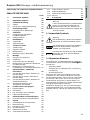
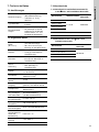
Table of contents
Conex
®
DIS-C
English (GB)
Installation and operating instructions. . . . . . . . . . . . . . . . . . . . . . . . . . . . . . . . . 4
Deutsch (DE)
Montage- und Betriebsanleitung . . . . . . . . . . . . . . . . . . . . . . . . . . . . . . . . . . . . 29
Español (ES)
Instrucciones de instalación y funcionamiento . . . . . . . . . . . . . . . . . . . . . . . . . 54
Français (FR)
Notice d'installation et de fonctionnement. . . . . . . . . . . . . . . . . . . . . . . . . . . . . 80
Italiano (IT)
Istruzioni di installazione e funzionamento . . . . . . . . . . . . . . . . . . . . . . . . . . . 105
Nederlands (NL)
Installatie- en bedieningsinstructies . . . . . . . . . . . . . . . . . . . . . . . . . . . . . . . . 130
Português (PT)
Instruções de instalação e funcionamento . . . . . . . . . . . . . . . . . . . . . . . . . . . 155
Declaration of conformity . . . . . . . . . . . . . . . . . . . . . . . . . . . . . . . . . . . . . . . . 180

English (GB)
4
English (GB) Installation and operating instructions
Original installation and operating instructions
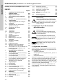
CONTENTS
Page
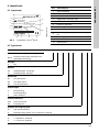
1. Symbols used in this document
2. General information
These installation and operating instructions contain
all information important for users of the
Conex
®
DIS-C:
• technical data
• instructions on commissioning, use and
maintenance
• safety information.
Should you require further information or should you
encounter problems that are not handled in sufficient
depth in this manual, please contact Grundfos.
We shall be pleased to support you with our
comprehensive know-how in the fields of measuring
and control technology as well as water treatment.
We always welcome suggestions on how to optimise
our installation and operating instructions to satisfy
our customers.
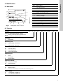
1. Symbols used in this document
4
2. General information
4
3. Description of the device
5
3.1 Assembly
5
3.2 Principles of conductivity measurement
5
4. Applications
6
4.1 Field of application for measurements
6
5. Safety
6
5.1 Obligations of the owner/operations
manager
6
5.2 Avoidance of danger
6
6. Identification
7
6.1 Nameplate
7
6.2 Type key
7
7. Technical data
8
7.1 Versions
8
7.2 General data
8
7.3 Measuring ranges
8
7.4 Dimensional sketches / drilling diagram
9
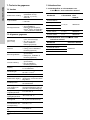
8. Installation
10
8.1 Transport and storage
10
8.2 Unpacking
10
8.3 Installation requirements
10
8.4 Assembling the Conex® DIS-C housing
for wall mounting
10
8.5 Assembling the Conex® DIS-C-P, CI
housing for installation in control panel
11
9. Commissioning / electrical
connections
11
9.1 Conex® DIS-C conductive, housing for
wall mounting
12
9.2 Conex® DIS-C inductive, housing for
wall mounting
13
9.3 Conex® DIS-C conductive, housing for
installation in control panel
14
9.4 Important instructions for connecting the
device
15
10. Principles of regulatory function
16
10.1 Regulatory behaviour
16
10.2 Limit values
16
10.3 On-off controller with P behaviour
17
10.4 Parameter settings
18
11. Initial operation and settings
19
11.1 Initial steps for operation
19
12. Operation
19
12.1 Device layout for Conex® DIS-C
19
12.2 Menu control
20
12.3 Navigation in the menus
20
12.4 Setup
21
12.5 Relay menu (S1 S2)
25
12.6 Temperature compensation
25
12.7 Displaying / changing code
26
12.8 Controller settings
26
12.9 Alarm value setting A1/A2
27
12.10 Service
28
13. Disposal
28
Warning
Prior to installation, read these installation
and operating instructions. Installation and
operation must comply with local
regulations and accepted codes of good
practice.
Warning
If these safety instructions are not
observed, it may result in personal injury.
Caution
If these safety instructions are not
observed, it may result in malfunction or
damage to the equipment.
Note
Notes or instructions that make the job
easier and ensure safe operation.

English (GB)
5
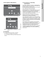
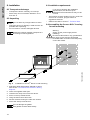
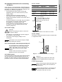
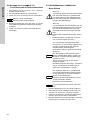
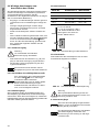
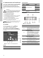
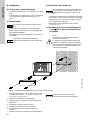
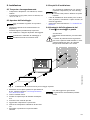
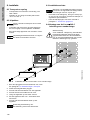
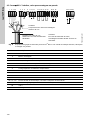
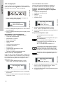
3. Description of the device
Fig. 1 Conex
®
DIS-C for wall mounting
Fig. 2 Conex
®
DIS-C for installation in control
panel
3.1 Assembly
The complete measuring system comprises:
• the measuring amplifier Conex
®
DIS-C
• the conductivity measuring cell with temperature
sensor.
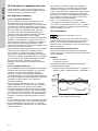
3.2 Principles of conductivity
measurement
In metallic conductors, electricity is transported by
freely moving electrons, whereas in electrolytes, the
electrical current is carried by ions.
All water-dissolved components that are in ionogenic
form contribute towards conductivity.
The conductivity is a sum parameter.
Different types of ions vary in their electrical charge
and migration rate. The migration rate is highly
dependent on temperature, which means the
influence of temperature must always be taken into
account when measuring conductivity.
Specific electrolytic conductivity is measured in
Siemens per cm (S/cm). Siemens per cm is the
reciprocal value of electrical resistance.
This measurement is based on a theoretical liquid
cube with sides of a length of 1 cm. In practice, cells
rarely have such an even geometric shape. The cell
constant C is used to specify the correlation between
the actual measured conductivity and the displayed
specific conductivity.
The measuring cell is inserted in a flow armature,
and the water to be measured flows around it.
The Conex
®
DIS-C measuring and regulation device
amplifies the signal from the measuring cell and
calculates the signal (e.g. against cable and
temperature compensation parameters). The result
is displayed digitally and can also be registered
using the analog output. The result is shown as an
actual value.
TM03 6980 3914TM03 6981 4506

English (GB)
6
4. Applications
The Conex
®
DIS-C is a measuring amplifier for
measuring conductivity using a conductive or
inductive measuring cell and for regulation of
disturbance variables using a connected control
element. Two controllers can be set separately as
limit values, intermittent pulse controllers or pulse
frequency controllers.
The Conex
®
DIS-C is available for installation in a
wall-mounted enclosure or for installation in a control
panel (only conductive measuring cell for
conductivity measurement).
4.1 Field of application for measurements
Principal uses:
• waste water treatment
• water purification
• recycling
• in metal processing industries
• in the chemical industry
• in the foodstuff industry.
5. Safety
The owner/operations manager of the system is
responsible for the following:
• compliance with country-specific safety
regulations
• training of operating personnel.
5.1 Obligations of the owner/operations
manager
The owner/operations manager must ensure that
persons working with the device described fulfil
these requirements:
• They are acquainted with the regulations
concerning working safety and accident
prevention.
• They have been trained in use of the device.
• They have read and understood the warning
information and handling symbols.
The owner/operations manager is also responsible
for ensuring that this manual is kept in the immediate
vicinity of the device and is always available for the
operating personnel.
5.2 Avoidance of danger
Warning
Installation and connection of the device
and the associated supplementary
components must only be carried out by
authorised personnel!
The local safety regulations must be
observed!
Switch off the power supply before
connecting the power cable and the relay
contacts!
Warning
Do not dismantle the device!
Cleaning, maintenance and repair must
only be carried out by authorised
personnel!
Warning
Other applications than those described in
section 4. Applications are not approved
and not permitted. Grundfos cannot be
held liable for any damage resulting from
incorrect use.
Caution
The mounting location must be selected so
that the housing is not subjected to
mechanical loading.
Check that all settings are correct before
starting up the device!

English (GB)
7
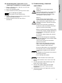
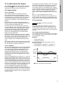
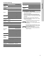
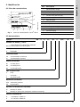
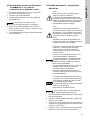
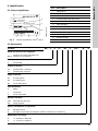
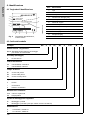
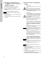
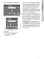
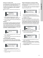
6. Identification
6.1 Nameplate
Fig. 3 Nameplate, Conex
®
DIS-C
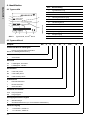
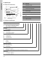
6.2 Type key
TM04 0331 3914
DIS-C 1-CC, W-G
351-2000-10006
S/N: 08/02809
Conex DIS-C, 230/240V 50/60Hz
10 VA, IP 65
96725733P1108030802809
1
2
3
4
5
67 8 9
10
11
12
Pos. Description
1 Type designation
2 Model
3 Product name
4 Power consumption [VA]
5 Product number
6 Country of origin
7 Enclosure class
8 Year and week of production
9 Marks of approval, CE mark, etc.
10 Voltage [V]
11 Frequency [Hz]
12 Serial number
Example: DIS -C -P CC -R1 -F -PVC W -G
Units for measurement and control
DIS-C
Dosing Instrumentation Standard for
conductivity measurement
Assembly
PPrepacked
Measuring cell
CC Conductivity, conductive
CI Conductivity, inductive
Measuring range
R1 0 to 200 μS/cm
R2 0 to 2000 μS/cm
R3 0 to 20,000 μS/cm
Armature type
FFlow
I Immersion
X No armature
Armature material
PVC Polyvinyl chloride
PP Polypropylene
Controller mounting option
W Wall-mounted
P Panel-mounted (only for conductive measuring cell)
Power supply
G 1 x 230/240 V, 50/60 Hz
H 1 x 115/120 V, 50/60 Hz

English (GB)
8
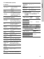
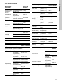
7. Technical data
7.1 Versions
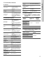
7.2 General data
7.3 Measuring ranges
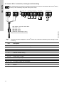
7.3.1 Measuring ranges and cell constants for
Conex
®
DIS-C with conductive measuring
cell
7.3.2 Measuring ranges for Conex
®
DIS-C with
inductive measuring cell
Power supply
• 230 V (± 10 %), 50/60 Hz
(standard version)
• 115/120 V (± 10 %),
50/60 Hz
Type of measuring
cell
• Conductive
• Inductive
Mounting variants
• For wall mounting
• For installation in control
panel (only Conex
®
DIS-C,
CI devices - with
conductive measuring cell).
Dimensions
(W x H x D)
• 165 x 160 x 80 mm
(for wall mounting)
• 96 x 96 x 127 mm (for
installation in control panel)
Weight
• 1.0 kg (for wall mounting)
• 0.8 kg (for installation in
control panel)
Enclosure class
• IP65 (wall-mounted)
• IP54 (front, installation in
control panel)
Internal fuse
• Yes (wall-mounted)
• No (installation in control
panel)
Display
LCD display, two lines,
2 x 16 characters
Connections
Terminal strips for cable up to
maximum 1.5 mm
2
Power consumption 10 VA
Electrical output
0 (4) to 20 mA galvanically
isolated, maximum load 500 Ω
Switching points
Can be set within the
measuring range
Contact rating for
regulation and alarm
relay
6 A / 250 V, maximum ohm
resistive load 550 VA
(with RC contact protection)
Permissible ambient
temperature
0 °C to +50 °C
Permissible storage
temperature
-20 °C to +65 °C
Maximum relative
humidity
90 % (non-condensing)
Adjustable
temperature
coefficient of
measurement
solution
0 to 8 % / °C
Proportional band Xp 1 to 3000 %
Reset time Tn 0 to 3000 seconds
Measuring range Cell constant
Conductive
measuring
cell
0 to 20 MΩ/cm
C = 0.05 96609150
0 to 2 μS/cm
0 to 20 μS/cm
0 to 200 μS/cm
0 to 2 mS/cm C = 0.2 96609151
0 to 20 mS/cm C = 1 96609152
Measuring range
Inductive measuring
cell
0 to 2.000 mS/cm
95720194
0 to 20.00 mS/cm
0 to 200.0 mS/cm
0 to 2000 mS/cm

English (GB)
9
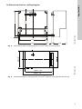
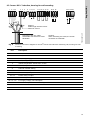
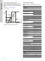
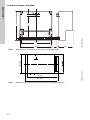
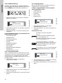
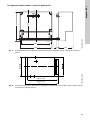
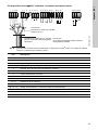
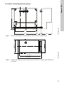
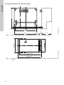
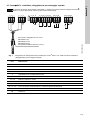
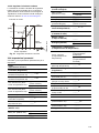
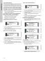
7.4 Dimensional sketches / drilling diagram
Fig. 4 Dimensional sketch / drilling diagram for Conex
®
DIS-C for wall mounting
Fig. 5 Dimensional sketch / mounting sketch for Conex
®
DIS-C for control-panel wall mounting
TM03 6982 4506TM03 6983 4506
10
72.5
1
6
0
165
151
1
2
0
1
5
approx. 129
approx. 137

English (GB)
10
8. Installation
8.1 Transport and storage
• Transport the device carefully, do not drop!
• Store at dry and cool location between -20 °C
and +65 °C.
8.2 Unpacking
• Check the device for damage. Install as soon as
possible after unpacking.
• Do not install or connect damaged devices!
8.3 Installation requirements
• The location must be vibration-free, dry, dust-free
and free of corrosive, pungent fumes or
aggressive solvents.
• Observe the data in section 7. Technical data.
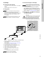
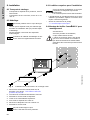
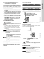
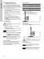
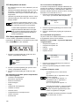
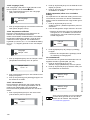
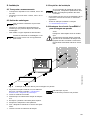
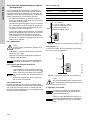
8.4 Assembling the Conex
®
DIS-C housing
for wall mounting
Fig. 6 Installation of Conex
®
DIS-C for wall mounting
1. Drill three dowel holes with a diameter of 8 mm.
See section 7.4 Dimensional sketches / drilling
diagram.
2. Insert the supplied dowel pins.
3. Unscrew the clamp cover from the device.
4. Screw in the top middle screw.
5. Hang the device onto this screw.
6. Secure the device using the other two screws.
7. Screw the clamp cover back on.
Caution
Do not allow any foreign bodies to enter!
Note
Retain the packing material or dispose of it
according to local regulations.
Caution
If you do not observe the installation
requirements, the device may be
damaged! The measurements may not be
correct!
Warning
Switch off the power supply before
installing!
Enclosure class IP65 is only guaranteed if
the clamp covers and the associated
threaded cable connections and temporary
covers are closed.
TM03 6985 4506
151
120
Caution
Do not damage the gasket.
The gasket must be fitted exactly.

English (GB)
11
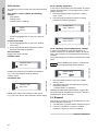
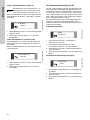
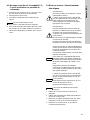
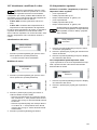
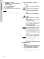
8.5 Assembling the Conex
®
DIS-C-P, CI
housing for installation in control panel
1. Make an opening of 92 + 0.8 mm x 92 + 0.8 mm
in the control panel.
2. Slip on the supplied gasket.
3. Insert the device into the opening from the front.
4. Hook the clamps into the tightening cones on the
sides at the top and bottom.
5. Secure the device from the rear using a
screwdriver.
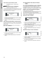
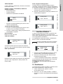
9. Commissioning / electrical
connections
1. Remove the terminal cover on the front of the
device.
2. Use the appropriate cable feedthroughs and
tighten the screws carefully.
3. Connect the cables used to the terminals
according to the Conex
®
DIS-C terminal
assignment.
4. Close the terminal cover again with correctly
positioned gasket.
Caution
Do not damage the gasket.
The gasket must be fitted exactly.
Warning
Switch off the power supply before
installing!
Enclosure class IP65 is only guaranteed
with the front panel of the terminals
enclosure closed and with appropriate
cable glands or dummy caps.
Warning
Switch off the power supply before
connecting the power supply cable and the
relay contacts! For safety reasons, the
protective conductor must be connected
correctly!
Observe the local safety regulations!
Protect the cable connections and plugs
against corrosion and humidity.
Caution
Before connecting the power supply cable,
check that the supply voltage specified on
the nameplate corresponds to the local
conditions!
An incorrect supply voltage may destroy
the device!
To ensure electromagnetic compatibility
(EMC), the input and current output cables
must be screened.
Connect the screening to the screen
ground on one side.
Refer to the wiring diagram! Route the
input, current output and power supply
cables in separate cable channels.
Caution
Enclosure class IP65 is only guaranteed if
the terminal cover is correctly sealed! Do
not damage the gasket on the terminal
cover!
The gasket on the terminal cover must be
positioned precisely!
Do not damage the gasket!
Note
Unused terminals must remain open.

English (GB)
12
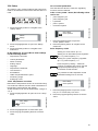
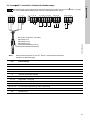
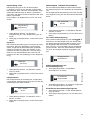
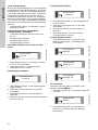
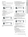
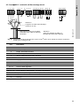
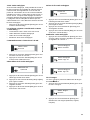
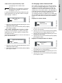
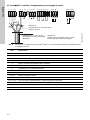
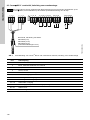
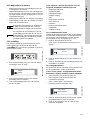
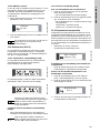
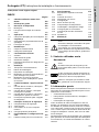
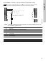
9.1 Conex
®
DIS-C conductive, housing for wall mounting
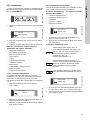
Fig. 7 Terminal connection diagram for Conex
®
DIS-C with conductive measuring cell, housing for wall
mounting
Caution
The measurement input must be screened! The screen must not be connected to the Conex
®
DIS-C,
but only to the measuring cell (outer casing of the cell)!
TM03 6986 3914
12
4
5
6
11 12
13
20
21
22
+
L
NPE
14
15 16
17
18 19
A
3
28
27
26
+
29
+
24V
With Pt100, connection with cable:
96611925 (5 m)
96611928 (15 m)
96611929 (25 m)
(maximum cable length: 50 m)
Pos. Description
1 White, inner electrode of measuring cell
2 Brown, outer electrode of measuring cell
4 Yellow, Pt100
5 Green, Pt100
A Trimmer contrast setting
11-12 0/4-20 mA output
14 / 15 Control relay 1 output
16 / 17 Control relay 2 output
18 / 19 Alarm relay 3 output
20 / 21 / 22 For supply voltage, see nameplate
26 / 27 Water sensor
28 Screen

English (GB)
13
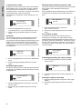
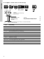
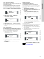
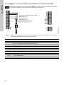
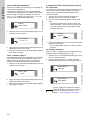
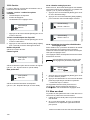
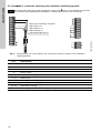
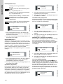
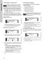
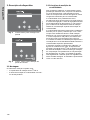
9.2 Conex
®
DIS-C inductive, housing for wall mounting
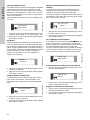
Fig. 8 Terminal connection diagram for Conex
®
DIS-C with inductive measuring cell, housing for wall
mounting
TM03 6987 4011
12
4
5
61112
13
20
21
22
+
L
N
PE
28
27
26
+
14
15 16
17
18 19
A
29
+
24V
3
3b
Connection with 6 m cable,
extendable with extension cable
95720380
Caution!
Cable length without screen:
maximum 30 mm
Caution!
When extending the cable, the screen
must also be extended!
Pos. Description
1 Green, measurement
2 White, screen
3 Red, voltage supply
3b Black, voltage supply screen
4 Yellow, temperature sensor NTC, screen
5 Brown, temperature sensor NTC
A Trimmer contrast setting
11 / 12 0/4 to 20 mA output
14 / 15 Control relay 1 output
16 / 17 Control relay 2 output
18 / 19 Alarm relay 3 output
20 / 21 / 22 For supply voltage, see nameplate
26 / 27 Water sensor (external controller stop)
28 +24 V
29 Screen

English (GB)
14
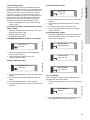
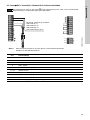
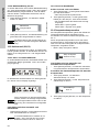
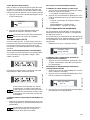
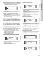
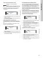
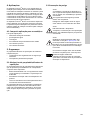
9.3 Conex
®
DIS-C conductive, housing for installation in control panel
Fig. 9 Terminal connection diagram for Conex
®
DIS-C with conductive measuring cell, housing for
installation in control panel
Caution
The screen must not be connected to the Conex
®
DIS-C, but only to the measuring cell. See the
installation and operating instructions for the measuring cell!
TM03 6988 4409
L1
N
PE
+
-
+
-
1
24
25
26
3
2
4
5
6
7
8
9
10
11
12
13
14
15
18
21
16
19
22
17
20
23
With Pt100, connection with cable:
96611925 (5 m)
96611928 (15 m)
96611929 (25 m)
(maximum length: 50 m)
Pos. Description
2 White, inner electrode of measuring cell
3 Brown, outer electrode of measuring cell
5 Yellow, Pt100
6 Green, Pt100
9 / 10 0/4 to 20 mA output
11 / 12 Water sensor
18 / 19 Control relay 1 output
20 / 21 Control relay 2 output
22 / 23 Alarm relay 3 output
24 / 25 / 26 For supply voltage, see nameplate

English (GB)
15
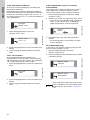
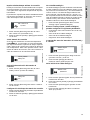
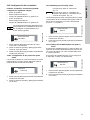
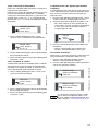
9.4 Important instructions for connecting
the device
As is common in microprocessor-controlled devices,
certain precautions must be taken during installation
and wiring. In addition to the general guidelines, the
following is of particular importance:
• Input wires and control wires must be laid
separately from one another and from power
supply cables.
• Analog output wires must be screened.
The screen can be connected to the device.
• Relays and protective spools must remain free of
interference.
• If inductive loads are connected, they must either
be screened, or the relay contact must be
protected on the clamping strip of the
Conex
®
DIS-C by an RC protective circuit, in
accordance with the following table and the
switching diagrams.
9.4.1 Power supply
• The device is connected to the power supply at
the clamps (L), (N) and (PE).
• Check the correct supply voltage on the
nameplate.
9.4.2 Connecting the conductivity measuring cell
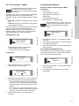
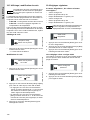
9.4.3 Relay outputs
If inductive loads (including relay and protective spools)
are connected, they must be screened. If this is not
possible, the relay contact must be protected using a
protection circuit in accordance with the table below.
For AC current
Fig. 10 Protection circuit with AC current
For DC voltage
The relay or protective spool must be screened with
a suppressor diode.
Fig. 11 Protection circuit with DC voltage
9.4.4 Current outputs
Warning
Before connecting the device, switch off
the power supply!
Caution
Connection of an incorrect supply voltage
may destroy the device!
Caution
For connecting the conductivity cell to the
Conex
®
DIS-C, only use the prescribed
cable. This cable must not be used in the
same cable channel as power supply
cables!
Protect cable connections and plugs
against corrosion and moisture!
Current up to Capacitor C Resistor R
60 mA 10 nF, 260 V 390 Ω, 2 W
70 mA 47 nF, 260 V 22 Ω, 2 W
150 mA 100 nF, 260 V 47 Ω, 2 W
1.0 A 220 nF, 260 V 47 Ω, 2 W
TM03 6990 4506TM03 7007 4506
Warning
If floating relay outputs are used, they
must be supplied with a backup fuse!
Caution
When connecting the electrical outputs, be
aware of the polarity and the maximum
load (500 Ω)!
Caution
Use a screened cable for connecting the
electrical outputs. The screen must be
connected to PE with one end.
R = 47 to 390 Ω
C = 10 nF to 220 nF / 260 V
e.g. Siemens MKC B 81 921
Values can be found in the
above table.
+
-

English (GB)
16
10. Principles of regulatory function
Freely selectable control functions mean that the
Conex
®
DIS-C controller can be adapted to a wide
variety of closed-loop control systems.
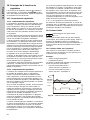
10.1 Regulatory behaviour
10.1.1 P regulation behaviour
The P controller has a static characteristic curve.
The characteristic proportional band for the P
controller is Xp. Within this range, which is limited to
a maximum or minimum depending on the control
direction, there is a proportional correlation between
the input and output quantities of the controller.
The lower limit is the response threshold of the
controller. This is the smallest regulatory deviation
that leads to a measurable control variable.
The upper limit separates the proportional band from
saturation. Above this limit, no further increase in
output signal is possible, regardless of increases in
the input signal. This range is called the control
range of the controller, and the control variable can
have any value within this range.
Due to the static characteristic curve, the P controller
cannot reach the setpoint in a stationary state.
This results in a consistent regulatory deviation,
which can be reduced by decreasing Xp, but which
cannot be completely eliminated using a P controller.
The controller reacts quicker with small Xp values.
The Xp value cannot, however, be reduced
arbitrarily, as this causes the controller to become
unstable.
10.1.2 I regulation behaviour
The non-delayed relationship between the regulatory
deviation and the control variable in a P controller
results in an undesirable persistent regulatory
deviation. However, if the regulatory deviation is
controlled directly by the regulating speed instead of
the control variable, this fixed assignment of the two
variables no longer applies. The result is an
integrated controller.
With a regulatory deviation of zero, i.e. when the
setpoint is equal to the actual value, the regulating
speed is also zero. Both positive and negative
regulatory deviations can be influenced by positive
or negative regulating speeds. The control variable
covers the whole control range. The control range of
the I controller is the range in which the regulatory
deviation controls the regulating speed in a linear
fashion.
The characteristic value of the I controller is the reset
time Tn. The reset time is the time that must elapse,
due to the integrated mode of action, for the step
response to reach the value that a P controller would
reach immediately.
The control circuit reacts slowly. If a regulatory
deviation results, an I controller can only react by
constantly changing its control variable. For this
reason, regulation with I controllers is always slower
than with controllers that act proportionally. If the
speed of the controller is increased by decreasing
the integration constant, the control circuit has a
slight tendency towards instability.
At Tn = 0, the controller has no I proportion.
In the absence of external influences, a control
circuit with an I controller therefore has no residual
regulatory deviation in a stationary state when the
control variable is constant.
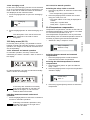
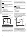
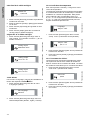
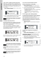
10.2 Limit values
In principle, the limit value only has two switching
states; ON and OFF. Depending on the set control
direction, the controller is deactivated when the
setpoint value is exceeded, or when the value drops
below the setpoint.
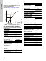
10.2.1 Limit values with hysteresis
To prevent constant switching when the setpoint
value is reached, it is possible to specify a hysteresis
for the controller.
Example:
• setpoint 600 μS/cm
• hysteresis 10 μS/cm.
The hysteresis band is arranged symmetrically
around the switching point.
• Switch-off point = measured value + hysteresis / 2
• Switch-on point = measured value - hysteresis / 2.
Fig. 12 Limit values with hysteresis
Note
Setting for a limit value: Xp = O.
TM03 6991 4506
t
605
600
595
µS/cm
µS/cm
µS/cm
1
0
Relay
605 μS/cm
600 μS/cm
595 μS/cm
μS/cm

English (GB)
17
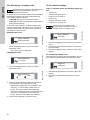
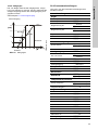
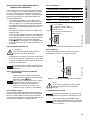
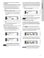
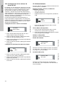
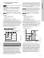
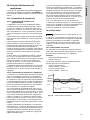
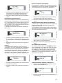
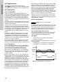
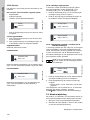
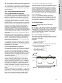
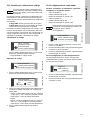
10.3 On-off controller with P behaviour
It is possible to use an on-off controller with P
behaviour as an intermittent pulse regulator or as a
pulse frequency regulator.
10.3.1 Intermittent pulse regulator
Example:
• setpoint = 6 mS/cm
• measuring range 0 to 10
• Xp = 30
• control direction = downwards.
Xp determines the size of the proportional band as a
percentage of the measuring range. In the following
example, this means that above 6 mS the relay
switches on, first with a short activation time and
then with an increasing activation time to 9 mS (the
total switching on + off time remains constant).
For greater measured values, the relay remains
constantly switched on.
Fig. 13 Intermittent pulse regulator
The intermittent pulse regulation offers the option to
recreate a constant controlling element using very
simple control elements, e.g. a magnetic valve.
Here, the relationship between switching on and off
is changed depending on the calculated control
variable. The total time (ON+OFF) is constant in
intermittent pulse regulation. The total time can be
set to between 1 and 99 seconds depending on the
control system. A setting of 10 seconds leads to a
good result in most cases.
If the calculated control variable is very low, in some
cases it is possible that the control element attached
here does not show a reaction within this short time.
In this case, it is possible to set a minimum drive
pulse. This can be within the range 0.1 to
9.9 seconds.
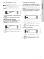
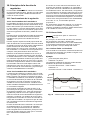
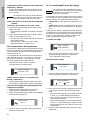
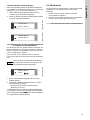
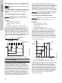
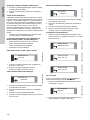
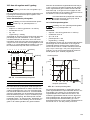
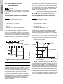
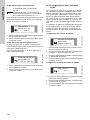
10.3.2 Pulse-frequency regulator
Example:
• setpoint = 6 mS/cm
• measuring range 0 to 10
• Xp = 20 or 40
• pulse frequency = 120
• control direction = downwards.
Xp determines the size of the proportional band as a
percentage of the measuring range. In the following
example, this means that impulses are output from
6 mS and constantly increase to 8 mS (Xp = 20) or
10 mS (Xp = 40). For higher measured values, the
prespecified maximum number of impulses (here
120/min) is output.
Fig. 14 Pulse-frequency regulator
The pulse frequency regulator in combination with an
appropriate control variable is almost the same as a
continuous controller. The disadvantages of the
impulse-driven control variable only becomes
apparent in the lower control variable range and with
a low maximum pulse frequency. The specification of
the maximum pulse frequency refers to 100 %
dosing flow and can be set within a range from 0 to
180 impulses per minute.
Note
Setting for an on-off controller: Xp > O.
Note
Setting for an intermittent pulse regulator:
Xp > O, pulse frequency = 0.
TM03 6992 4506
SP setpoint
MV measured value
6
7
8
9
T
ON
T
ON
T
[]mS/cm
2 3
0 1
4 5
6 7
8
10
9
[mS ]/cm
SP
MV
MV
[mS/cm]
[mS/cm]
Note
The intermittent pulse period must always
be at least twice as long as the minimum
switch-on time!
Note
Setting for a pulse-frequency regulator:
Xp > O, pulse frequency > 0.
TM03 6993 4506
0
30
60
90
100%
6
789
10
120
Xp = 40
Xp = 20
[1 min]/
Pulse frequency
Measured
value
Setpoint
[1/min]
[mS/cm]

English (GB)
18
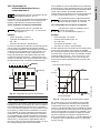
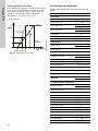
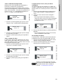
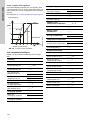
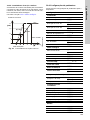
10.3.3 Continuous action controllers
The control variables calculated by the controller
based on the setpoint S1 or S2 can optionally be
output as a continuous control signal via the analog
output.
See section 12.4.4 Analog output.
Fig. 15 Continuous-action controllers
10.4 Parameter settings
Make a note here of the parameter settings for the
device.
TM03 6994 4506
0
5
10
15
100%
6
789
10
20
Xp = 40
Xp = 20
[mA]
Current output
Measured
value
Setpoint
[m/A]
[mS/cm]
Setup
Controller
Pulse freq. S1 _____ / min
Pulse freq. S2 _____ / min
Ctrl. direction S1
__ downward
__ upward
Ctrl. direction S2
__ downward
__ upward
Hysteresis _____ μS
Int. pulse period _____ s
Min. switch-on _____ s
Delay control
Delay ctrl.
__ off
__ on
Delay ctrl. _____ s
Analog output
Select output
__ 0-20 mA
__ 4-20 mA
Start 0/4 mA _____ μS
End 20 mA _____ μS
Analog output __ measured value
Temper. coeff. _____ % / °C
Cell const. _____
Measur. range _____
Averaging
__ on
__ off
Temperature compensation
Temp. compens.
__ Automat.comp.
__ Manual comp.
Manual temp. _____ °C
Controller settings
Setpoint 1 _____ μS
Prop. band XP S1 _____ μS
Reset time TN S1 _____ s
Setpoint 2 _____ μS
Prop. band XP S2 _____ μS
Reset time TN S2 _____ s
Alarm
Alarm value A1 _____ μS
Alarm value A2 _____ μS
Delay _____ s

English (GB)
19
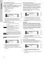
11. Initial operation and settings
11.1 Initial steps for operation
Once the assembly and connection steps have been
completed, carry out the following steps when using
the device for the first time.
1. Switch on the power supply.
2. If required, set the measuring range.
3. Check the entered cell constants.
4. If necessary, perform a cable compensation (for a
conductive measuring cell).
5. Set the parameters for the device function.
Check the outputs and secondary devices.
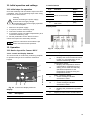
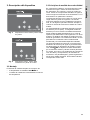
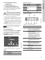
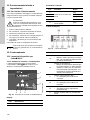
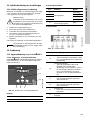
12. Operation
12.1 Device layout for Conex
®
DIS-C
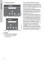
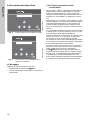
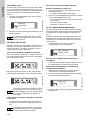
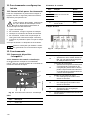
12.1.1 Control and display elements
The Conex
®
DIS-C conductivity measuring amplifier
is operated using a touch-sensitive membrane
keypad.
Fig. 16 Control and display elements
Display
Control elements
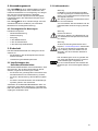
Display fields
Fig. 17 Display fields
Warning
Before connecting the power supply,
ensure that the supply voltage
corresponds to the power supply specified
on the nameplate!
Note
Notes or instructions that make the job
easier and ensure safe operation.
TM03 6995 4506
Pos. Description
1LCD display
1
2
6
345
Pos. Function Name
2
Menu control button
[Up]
3[Left]
4[Down]
5 [Right]
6
Button for returning to
start menu
[OK]
TM03 6996 4506
Pos. Description
1a
Measuring value display
• Displays the current measured value
in MΩ, μS, mS (depending on the
selected measuring range).
1b
Temperature display
• Displays the temperature used for
compensation. Depending on the
setting, this is either the manually
specified temperature or the
temperature measured using the
temperature sensor.
1c
Relay 1 switching status
• A filled rectangle indicates
switched-on status.
1d
Relay 2 switching status
• A filled rectangle indicates
switched-on status.
1e
Control function
• Displays the preselected regulation
type.
1f Display of active menu control buttons.

English (GB)
20
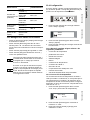
12.2 Menu control
12.3 Navigation in the menus
• To navigate in and between menus, use the [Up]
and [Down] buttons.
• Use the [Right] button to open the menu next to
it. The currently active menu control buttons are
displayed in the corresponding line.
• Use the [Left] button to save values.
• Use [OK] to exit the menu and return to the start
display.
Main menu Default values
Temp. compens.
Temp. compens. Manual comp.
Manual temp. 025 °C
Enter password Enter password Code 086
Controller
Setpoint S1 02.5 μS
Prop. and xp S1 10 %
Reset time TN S1 000 s
Setpoint S2 02.0 μS
Prop. band xp S2 10 %
Reset time TN S2 000 s
Alarm values
Alarm value A1 00.0 μS
Alarm value A2 02.0 μS
Delay 0.05 s
Setup See table below
Service See table below
Setup menu Default values
Corr. temp. Corr. temp. 0 °C
Contr. param.
Pulse freq. S1 0-180 / min
Pulse freq. S2 0-180 / min
Ctrl. direction S1 Downward control
Ctrl. direction S2 Upward control
Hysteresis 00.1 μS
Int. pulse period 10 s
Min. switch-on 0.5 s
Delay ctrl.
Delay ctrl. off
Delay ctrl. 180 s
Analog output
Select output 0-20 mA
Start 0/4 mA 00.0 μS
End 20 mA 200.0 μS
Analog output Measured value
Language Sel. language Deutsch
Temper. coeff. Temper. coeff. 0.0 % / °C
Cell const. Cell const. 0.050
Cable
compens.
Cable compens. 00.0 μS
Measur. range Measur. range 20.00 μS
Averaging Averaging off
Service menu Default values
Product info
Unit No. No. 041
Software date M/Y 1.00
Product. date M/Y 1.00
Analog input
Input 1 -019
Input 2 000 °C
Delete setting Delete setting
Note
Important menu selections and changes to
data are code-protected to prevent
unauthorised access.
Note
The order of the settings in the following
section is different to the order of menu
navigation. This section describes the
basic settings that are made first during
setup.
La pagina sta caricando ...
La pagina sta caricando ...
La pagina sta caricando ...
La pagina sta caricando ...
La pagina sta caricando ...
La pagina sta caricando ...
La pagina sta caricando ...
La pagina sta caricando ...
La pagina sta caricando ...
La pagina sta caricando ...
La pagina sta caricando ...
La pagina sta caricando ...
La pagina sta caricando ...
La pagina sta caricando ...
La pagina sta caricando ...
La pagina sta caricando ...
La pagina sta caricando ...
La pagina sta caricando ...
La pagina sta caricando ...
La pagina sta caricando ...
La pagina sta caricando ...
La pagina sta caricando ...
La pagina sta caricando ...
La pagina sta caricando ...
La pagina sta caricando ...
La pagina sta caricando ...
La pagina sta caricando ...
La pagina sta caricando ...
La pagina sta caricando ...
La pagina sta caricando ...
La pagina sta caricando ...
La pagina sta caricando ...
La pagina sta caricando ...
La pagina sta caricando ...
La pagina sta caricando ...
La pagina sta caricando ...
La pagina sta caricando ...
La pagina sta caricando ...
La pagina sta caricando ...
La pagina sta caricando ...
La pagina sta caricando ...
La pagina sta caricando ...
La pagina sta caricando ...
La pagina sta caricando ...
La pagina sta caricando ...
La pagina sta caricando ...
La pagina sta caricando ...
La pagina sta caricando ...
La pagina sta caricando ...
La pagina sta caricando ...
La pagina sta caricando ...
La pagina sta caricando ...
La pagina sta caricando ...
La pagina sta caricando ...
La pagina sta caricando ...
La pagina sta caricando ...
La pagina sta caricando ...
La pagina sta caricando ...
La pagina sta caricando ...
La pagina sta caricando ...
La pagina sta caricando ...
La pagina sta caricando ...
La pagina sta caricando ...
La pagina sta caricando ...
La pagina sta caricando ...
La pagina sta caricando ...
La pagina sta caricando ...
La pagina sta caricando ...
La pagina sta caricando ...
La pagina sta caricando ...
La pagina sta caricando ...
La pagina sta caricando ...
La pagina sta caricando ...
La pagina sta caricando ...
La pagina sta caricando ...
La pagina sta caricando ...
La pagina sta caricando ...
La pagina sta caricando ...
La pagina sta caricando ...
La pagina sta caricando ...
La pagina sta caricando ...
La pagina sta caricando ...
La pagina sta caricando ...
La pagina sta caricando ...
La pagina sta caricando ...
La pagina sta caricando ...
La pagina sta caricando ...
La pagina sta caricando ...
La pagina sta caricando ...
La pagina sta caricando ...
La pagina sta caricando ...
La pagina sta caricando ...
La pagina sta caricando ...
La pagina sta caricando ...
La pagina sta caricando ...
La pagina sta caricando ...
La pagina sta caricando ...
La pagina sta caricando ...
La pagina sta caricando ...
La pagina sta caricando ...
La pagina sta caricando ...
La pagina sta caricando ...
La pagina sta caricando ...
La pagina sta caricando ...
La pagina sta caricando ...
La pagina sta caricando ...
La pagina sta caricando ...
La pagina sta caricando ...
La pagina sta caricando ...
La pagina sta caricando ...
La pagina sta caricando ...
La pagina sta caricando ...
La pagina sta caricando ...
La pagina sta caricando ...
La pagina sta caricando ...
La pagina sta caricando ...
La pagina sta caricando ...
La pagina sta caricando ...
La pagina sta caricando ...
La pagina sta caricando ...
La pagina sta caricando ...
La pagina sta caricando ...
La pagina sta caricando ...
La pagina sta caricando ...
La pagina sta caricando ...
La pagina sta caricando ...
La pagina sta caricando ...
La pagina sta caricando ...
La pagina sta caricando ...
La pagina sta caricando ...
La pagina sta caricando ...
La pagina sta caricando ...
La pagina sta caricando ...
La pagina sta caricando ...
La pagina sta caricando ...
La pagina sta caricando ...
La pagina sta caricando ...
La pagina sta caricando ...
La pagina sta caricando ...
La pagina sta caricando ...
La pagina sta caricando ...
La pagina sta caricando ...
La pagina sta caricando ...
La pagina sta caricando ...
La pagina sta caricando ...
La pagina sta caricando ...
La pagina sta caricando ...
La pagina sta caricando ...
La pagina sta caricando ...
La pagina sta caricando ...
La pagina sta caricando ...
La pagina sta caricando ...
La pagina sta caricando ...
La pagina sta caricando ...
La pagina sta caricando ...
La pagina sta caricando ...
La pagina sta caricando ...
La pagina sta caricando ...
La pagina sta caricando ...
La pagina sta caricando ...
La pagina sta caricando ...
La pagina sta caricando ...
La pagina sta caricando ...
La pagina sta caricando ...
-
 1
1
-
 2
2
-
 3
3
-
 4
4
-
 5
5
-
 6
6
-
 7
7
-
 8
8
-
 9
9
-
 10
10
-
 11
11
-
 12
12
-
 13
13
-
 14
14
-
 15
15
-
 16
16
-
 17
17
-
 18
18
-
 19
19
-
 20
20
-
 21
21
-
 22
22
-
 23
23
-
 24
24
-
 25
25
-
 26
26
-
 27
27
-
 28
28
-
 29
29
-
 30
30
-
 31
31
-
 32
32
-
 33
33
-
 34
34
-
 35
35
-
 36
36
-
 37
37
-
 38
38
-
 39
39
-
 40
40
-
 41
41
-
 42
42
-
 43
43
-
 44
44
-
 45
45
-
 46
46
-
 47
47
-
 48
48
-
 49
49
-
 50
50
-
 51
51
-
 52
52
-
 53
53
-
 54
54
-
 55
55
-
 56
56
-
 57
57
-
 58
58
-
 59
59
-
 60
60
-
 61
61
-
 62
62
-
 63
63
-
 64
64
-
 65
65
-
 66
66
-
 67
67
-
 68
68
-
 69
69
-
 70
70
-
 71
71
-
 72
72
-
 73
73
-
 74
74
-
 75
75
-
 76
76
-
 77
77
-
 78
78
-
 79
79
-
 80
80
-
 81
81
-
 82
82
-
 83
83
-
 84
84
-
 85
85
-
 86
86
-
 87
87
-
 88
88
-
 89
89
-
 90
90
-
 91
91
-
 92
92
-
 93
93
-
 94
94
-
 95
95
-
 96
96
-
 97
97
-
 98
98
-
 99
99
-
 100
100
-
 101
101
-
 102
102
-
 103
103
-
 104
104
-
 105
105
-
 106
106
-
 107
107
-
 108
108
-
 109
109
-
 110
110
-
 111
111
-
 112
112
-
 113
113
-
 114
114
-
 115
115
-
 116
116
-
 117
117
-
 118
118
-
 119
119
-
 120
120
-
 121
121
-
 122
122
-
 123
123
-
 124
124
-
 125
125
-
 126
126
-
 127
127
-
 128
128
-
 129
129
-
 130
130
-
 131
131
-
 132
132
-
 133
133
-
 134
134
-
 135
135
-
 136
136
-
 137
137
-
 138
138
-
 139
139
-
 140
140
-
 141
141
-
 142
142
-
 143
143
-
 144
144
-
 145
145
-
 146
146
-
 147
147
-
 148
148
-
 149
149
-
 150
150
-
 151
151
-
 152
152
-
 153
153
-
 154
154
-
 155
155
-
 156
156
-
 157
157
-
 158
158
-
 159
159
-
 160
160
-
 161
161
-
 162
162
-
 163
163
-
 164
164
-
 165
165
-
 166
166
-
 167
167
-
 168
168
-
 169
169
-
 170
170
-
 171
171
-
 172
172
-
 173
173
-
 174
174
-
 175
175
-
 176
176
-
 177
177
-
 178
178
-
 179
179
-
 180
180
-
 181
181
-
 182
182
-
 183
183
-
 184
184


Grundfos Conex DIS-C Installation and Operating Instructions
- Tipo
- Installation and Operating Instructions
in altre lingue
- English: Grundfos Conex DIS-C
- français: Grundfos Conex DIS-C
- español: Grundfos Conex DIS-C
- Deutsch: Grundfos Conex DIS-C
- Nederlands: Grundfos Conex DIS-C
- português: Grundfos Conex DIS-C
Documenti correlati
-
Grundfos Conex DIS-C Installation And Operating Instructions Manual
-
Grundfos Conex DIA-1 Installation And Operating Instructions Manual
-
-
-
-
Altri documenti
-
 Chemitec 4222 Technical Manual
-
Omega CN142 Series Manuale del proprietario
-
Omega CN243 Series Manuale del proprietario
-
-
ABB CC-U/RTDR Istruzioni per l'uso
-
Eurotherm 3200 Guida utente
-
Carel HumiSteam UE Series Manuale utente
-
Mettler Toledo IND110 Scheda dati
-
Schneider Electric RENF22R2MMW Istruzioni per l'uso
-
Hach POLYMETRON 8362 Manuale utente
