Moxa OnCell G3101/G3201 Series Manuale utente
- Categoria
- Software di gestione della rete
- Tipo
- Manuale utente

OnCell G3111/G3151/G3211/G3251
Series User’s Manual
Edition 4.0, January 2018
www.moxa.com/product
© 2018 Moxa Inc. All rights reserved.

OnCell G3111/G3151/G3211/G3251
Series User’s Manual
The software described in this manual is furnished under a license agreement and may be used only in accordance with
the terms of that agreement.
Copyright Notice
© 2018 Moxa Inc. All rights reserved.
Trademarks
The MOXA logo is a registered trademark of Moxa Inc.
All other trademarks or registered marks in this manual belong to their respective manufacturers.
Disclaimer
Information in this document is subject to change without notice and does not represent a commitment on the part of
Moxa.
Moxa provides this document as is, without warranty of any kind, either expressed or implied, including, but not limited
to, its particular purpose. Moxa reserves the right to make improvements and/or changes to this manual, or to the
products and/or the programs described in this manual, at any time.
Information provided in this manual is intended to be accurate and reliable. However, Moxa assumes no responsibility for
its use, or for any infringements on the rights of third parties that may result from its use.
This product might include unintentional technical or typographical errors. Changes are periodically made to the
information herein to correct such errors, and these changes are incorporated into new editions of the publication.
Technical Support Contact Information
www.moxa.com/support
Moxa Americas
Toll
-free: 1-888-669-2872
Tel:
+1-714-528-6777
Fax:
+1-714-528-6778
Moxa China (Shanghai office)
Toll
-free: 800-820-5036
Tel:
+86-21-5258-9955
Fax:
+86-21-5258-5505
Moxa Europe
Tel:
+49-89-3 70 03 99-0
Fax:
+49-89-3 70 03 99-99
Moxa Asia
-Pacific
Tel:
+886-2-8919-1230
Fax:
+886-2-8919-1231
Moxa India
Tel:
+91-80-4172-9088
Fax:
+91-80-4132-1045

Table of Contents
1. Introduction ...................................................................................................................................... 1-1
Overview ........................................................................................................................................... 1-2
Package Checklist ............................................................................................................................... 1-2
Product Features ................................................................................................................................ 1-2
Product Specifications ......................................................................................................................... 1-3
2. Getting Started ................................................................................................................................. 2-1
Panel Layout ...................................................................................................................................... 2-2
OnCell G3111/G3151/G3211/G3251 .............................................................................................. 2-2
Connecting the Hardware .................................................................................................................... 2-3
Wiring Requirements ................................................................................................................... 2-3
SIM Card Installation ................................................................................................................... 2-4
DIN-Rail Mounting ....................................................................................................................... 2-5
Connecting the Power .................................................................................................................. 2-5
Connecting to the Network ........................................................................................................... 2-5
Connecting to a Serial Device ....................................................................................................... 2-5
Adjustable Pull High/Low Resistors for the RS-485 Port (G3151/G3251) ............................................. 2-6
LED Indicators ............................................................................................................................ 2-6
Reset Button ............................................................................................................................... 2-7
3. Initial IP Address Configuration ........................................................................................................ 3-1
Static and Dynamic IP Addresses .......................................................................................................... 3-2
Factory Default IP Address ................................................................................................................... 3-2
Configuration Options .......................................................................................................................... 3-2
OnCell Search Utility .................................................................................................................... 3-2
Web Console ............................................................................................................................... 3-2
ARP ........................................................................................................................................... 3-3
Telnet Console ............................................................................................................................ 3-4
Serial Console ............................................................................................................................. 3-7
4. Introducing Serial Port Operation Modes .......................................................................................... 4-1
Overview ........................................................................................................................................... 4-2
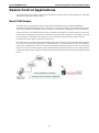
Device Control Applications .................................................................................................................. 4-3
Real COM Modes ......................................................................................................................... 4-3
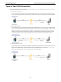
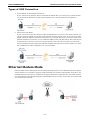
Types of Real COM Connection ...................................................................................................... 4-4
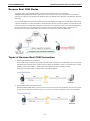
Reverse Real COM Modes ............................................................................................................. 4-5
Types of Reverse Real COM Connection .......................................................................................... 4-5
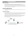
RFC 2217 Mode ........................................................................................................................... 4-6
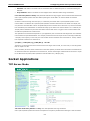
Socket Applications ............................................................................................................................. 4-6
TCP Server Modes ....................................................................................................................... 4-6
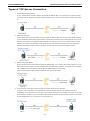
Types of TCP Server Connection .................................................................................................... 4-7
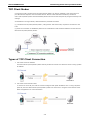
TCP Client Modes ........................................................................................................................ 4-8
Types of TCP Client Connection ..................................................................................................... 4-8
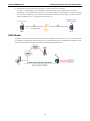
UDP Mode .................................................................................................................................. 4-9
Types of UDP Connection ........................................................................................................... 4-10
Ethernet Modem Mode ....................................................................................................................... 4-10
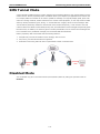
SMS Tunnel Mode ............................................................................................................................. 4-11
Disabled Mode .................................................................................................................................. 4-11
5. Introducing OnCell Central Manager and Ethernet Operation Modes ................................................. 5-1
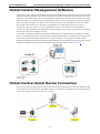
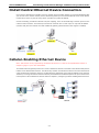
OnCell Central Management Software ................................................................................................... 5-2
OnCell Central Serial Device Connection ................................................................................................ 5-2
OnCell Central Ethernet Device Connection ............................................................................................ 5-3
Cellular-Enabling Ethernet Device ......................................................................................................... 5-3
6. Using the Web Console ...................................................................................................................... 6-1
Using Your Web Browser...................................................................................................................... 6-2
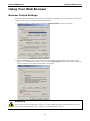
Browser Cookie Settings............................................................................................................... 6-2
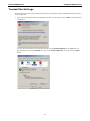
Trusted Site Settings ................................................................................................................... 6-3
Opening the Web Console............................................................................................................. 6-4
Web Console Navigation ...................................................................................................................... 6-5
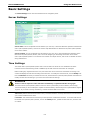
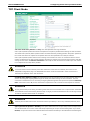
Basic Settings .................................................................................................................................... 6-6
Server Settings ........................................................................................................................... 6-6
Time Settings ............................................................................................................................. 6-6
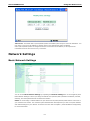
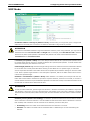
Network Settings ................................................................................................................................ 6-7
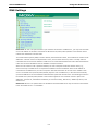
Basic Network Settings ................................................................................................................ 6-7
DNS Settings .............................................................................................................................. 6-9
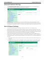
Advanced Network Settings ........................................................................................................ 6-10
Auto IP Report Settings .............................................................................................................. 6-10
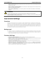
GuaranLink Settings .......................................................................................................................... 6-11
Overview .................................................................................................................................. 6-11

Background .............................................................................................................................. 6-11
Common Settings ...................................................................................................................... 6-11
GuaranLink Check Settings ......................................................................................................... 6-12
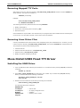
7. Cellular Network Settings ................................................................................................................. 7-1
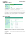
GSM GPRS Settings ............................................................................................................................. 7-2
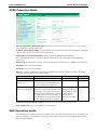
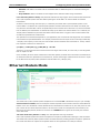
GSM Operation Mode ................................................................................................................... 7-2
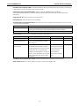
GPRS Operation Mode .................................................................................................................. 7-4
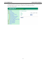
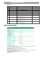
SMS Operation mode ................................................................................................................... 7-4
8. Configuring Serial Port Operation Modes .......................................................................................... 8-1
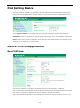
Port Setting Basics .............................................................................................................................. 8-2
Device Control Applications .................................................................................................................. 8-2
Real COM Mode ........................................................................................................................... 8-2
Reverse Real COM Mode ............................................................................................................... 8-5
RFC2217 Mode ............................................................................................................................ 8-8
Socket Applications ............................................................................................................................. 8-9
TCP Server Mode ......................................................................................................................... 8-9
TCP Client Mode ........................................................................................................................ 8-12
UDP Mode ................................................................................................................................ 8-15
Ethernet Modem Mode ....................................................................................................................... 8-16
SMS Tunnel Mode ............................................................................................................................. 8-19
Disabled Mode .................................................................................................................................. 8-21
9. Configuring the Cellular-Enabling ...................................................................................................... 9-1
Host to OnCell via Cellular ................................................................................................................... 9-2
10. Additional Serial Port Settings ........................................................................................................ 10-1
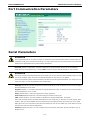
Port Communication Parameters ......................................................................................................... 10-2
Serial Parameters ............................................................................................................................. 10-2
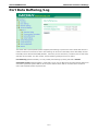
Port Data Buffering/Log ..................................................................................................................... 10-3
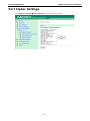
Port Cipher Settings .......................................................................................................................... 10-4
11. System Management Settings ......................................................................................................... 11-1
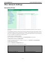
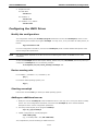
Misc. Network Settings ...................................................................................................................... 11-2
Accessible IP List ....................................................................................................................... 11-2
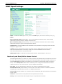
SNMP Agent Settings ................................................................................................................. 11-3
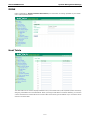
DDNS ...................................................................................................................................... 11-4
Host Table ................................................................................................................................ 11-4
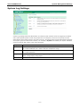
System Log Settings .................................................................................................................. 11-5
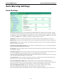
Auto Warning Settings ....................................................................................................................... 11-6
Event Settings .......................................................................................................................... 11-6
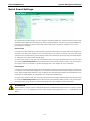
Serial Event Settings ................................................................................................................. 11-7
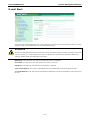
E-mail Alert .............................................................................................................................. 11-8
SNMP Trap ............................................................................................................................... 11-9
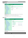
SMS Alert ................................................................................................................................. 11-9
Customized SMS ..................................................................................................................... 11-10
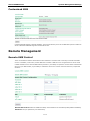
Remote Management ...................................................................................................................... 11-10
Remote SMS Control ................................................................................................................ 11-10
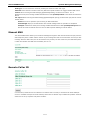
Manual SMS ............................................................................................................................ 11-11
Remote Caller ID ..................................................................................................................... 11-11
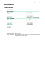
Maintenance .................................................................................................................................. 11-12
Console Setting ....................................................................................................................... 11-12
Ping ....................................................................................................................................... 11-13
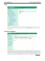
Firmware Upgrade ................................................................................................................... 11-13
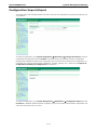
Configuration Import/Export ..................................................................................................... 11-14
Load Factory Defaults .............................................................................................................. 11-15
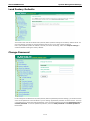
Change Password .................................................................................................................... 11-15
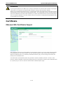
Certificate ...................................................................................................................................... 11-16
Ethernet SSL Certificate Import ................................................................................................. 11-16
Certificate/Key Delete .............................................................................................................. 11-17
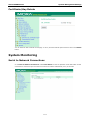
System Monitoring .......................................................................................................................... 11-17
Serial to Network Connections .................................................................................................. 11-17
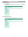
Serial Port Status .................................................................................................................... 11-18
Serial Port Error Count ............................................................................................................. 11-18
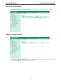
Serial Port Settings .................................................................................................................. 11-19
Cipher Usage Status ................................................................................................................ 11-19
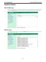
System Status ................................................................................................................................ 11-20
Serial Data Log ....................................................................................................................... 11-20
System Log ............................................................................................................................ 11-20
Network Status .............................................................................................................................. 11-21
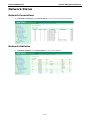
Network Connections ............................................................................................................... 11-21
Network Statistics ................................................................................................................... 11-21
Routing .................................................................................................................................. 11-22
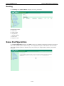
Save Configuration ......................................................................................................................... 11-22

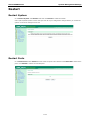
Restart .......................................................................................................................................... 11-23
Restart System ....................................................................................................................... 11-23
Restart Ports .......................................................................................................................... 11-23
12. Software Installation/Configuration ............................................................................................... 12-1
Overview ......................................................................................................................................... 12-2
Windows Driver Manager ................................................................................................................... 12-2
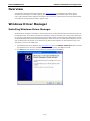
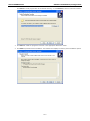
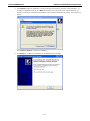
Installing Windows Driver Manager .............................................................................................. 12-2
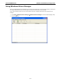
Using Windows Driver Manager ................................................................................................... 12-5
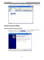
OnCell Search Utility ....................................................................................................................... 12-15
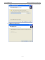
Installing OnCell Search Utility .................................................................................................. 12-15
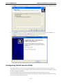
Configuring OnCell Search Utility ............................................................................................... 12-17
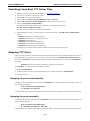
Moxa OnCell Linux Real TTY Driver.................................................................................................... 12-21
Basic Procedure ...................................................................................................................... 12-21
Hardware Setup ...................................................................................................................... 12-21
Installing Linux Real TTY Driver Files ......................................................................................... 12-22
Mapping TTY Ports ................................................................................................................... 12-22
Removing Mapped TTY Ports ..................................................................................................... 12-23
Removing Linux Driver Files ...................................................................................................... 12-23
Moxa OnCell UNIX Fixed TTY Driver .................................................................................................. 12-23
Installing the UNIX Driver ........................................................................................................ 12-23
Configuring the UNIX Driver ..................................................................................................... 12-24
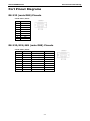
A. Pinouts and Cable Wiring .................................................................................................................. A-1
Port Pinout Diagrams .......................................................................................................................... A-2
RS-232 (male DB9) Pinouts .......................................................................................................... A-2
RS-232/422/485 (male DB9) Pinouts ............................................................................................. A-2
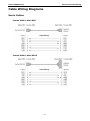
Cable Wiring Diagrams ........................................................................................................................ A-3
Serial Cables .............................................................................................................................. A-3
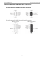
Pin Assignments for DB9 and DB25 Connectors ............................................................................... A-4
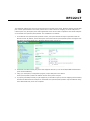
B. RFC2217 ............................................................................................................................................ B-1
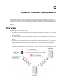
C. Dynamic Domain Name Server .......................................................................................................... C-1
Overview ........................................................................................................................................... C-1
Configuration ..................................................................................................................................... C-2
D. Well Known Port Numbers ................................................................................................................ D-1
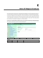
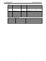
E. Auto IP Report Protocol .................................................................................................................... E-1
F. GSM Alphabet .................................................................................................................................... F-1
G. Default Settings ................................................................................................................................ G-1

1
1. Introduction
The G3111/G3151/G3211/G3251 series of cellular IP gateways have many exceptional features. There are
currently four models in the G3111/G3151/G3211/G3251 series of IP gateways: the OnCell G3111, OnCell
G3151, OnCell G3211, and OnCell G3251. The main differences between the models are the serial interface
types. Cellular IP gateways give you an easy way to connect your serial devices to cellular mobile networks.
The following topics are covered in this chapter:
Overview
Package Checklist
Product Features
Product Specifications

OnCell G3000 Series Introduction
1-2
Overview
OnCell G3111/G3151/G3211/G3251 gateways can be used to connect any serial device to a cellular network
and support a number of different operation modes. The OnCell COM driver turns the OnCell
G3111/G3151/G3211/G3251’s serial ports into virtual COM ports that allow you to communicate with your
serial device remotely over the cellular network. The OnCell G3111/G3151/G3211/G3251 comes pre-installed
with the TCP/IP protocol suite to transmit data back and forth between the serial device and GSM/GPRS
network.
For some applications, serial data must be delivered reliably even if communication is disrupted. The OnCell
G3111/G3151/G3211/G3251 provides a function to ensure that serial data is buffered in case of a
communication failure. When a communication failure occurs, the serial data is buffered in the OnCell
G3111/G3151/G3211/G3251 until communication is resumed, at which point the buffered data is sent to its
destination.
Package Checklist
Each OnCell G3111/G3151/G3211/G3251 serial cellular IP Gateway is shipped in a separate box with standard
accessories. In addition, several optional accessories can be ordered separately. When you receive your
shipment, check the contents of the box carefully, and notify your Moxa sales representative if any of the items
are missing or appear to be damaged.
G3111/G3151/G3211/G3251 cellular IP gateways are shipped with the following items:
Standard Accessories
• Rubber SMA antenna (model name: ANT-CQB-ASM-1)
• Din-rail kit
• Rubber stand
• DC Power Supply (screw-on)
• Product warranty statement
• Quick installation guide (printed)
• Warranty card
Optional Accessories
• ANT-CQB-AHSM-00-3m: Omni 0dBi/10cm, magnetic SMA quad-band antenna (impedance = 50 ohms),
3 m
• ANT-CQB-AHSM-03-3m: Omni 3dBi/25cm, magnetic SMA quad-band antenna (impedance = 50 ohms),
3 m
• ANT-CQB-AHSM-05-3m: Omni 5dBi/37cm, magnetic SMA quad-band antenna (impedance = 50 ohms),
3 m
Product Features
All models in the G3111/G3151/G3211/G3251 have the following features:
• Quad-band 900/1800, 850/1900 MHz GSM/GPRS.
• Versatile operation modes, including Real COM, Reverse Real COM, RFC2217, TCP Server, TCP Client, UDP,
Ethernet Modem, and SMS Tunnel.
• Private IP management software.
• Port buffering function to prevent loss of serial data when communication is disrupted.
• Adjustable baudrate feature for easy configuration of custom baudrates.
• LED indicators for status and signal level.

OnCell G3000 Series Introduction
1-3
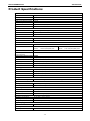
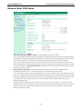
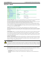
Product Specifications
Cellular Interface
Standards GSM/GPRS
Band Options Quad-band 850/900 and 1800/1900 MHz
GPRS Multi-slot Class Class 10
GPRS Terminal Device Class Class B
GPRS Coding Schemes CS1 to CS4
Tx Power 1 watt GSM 1800/1900, 2 watts EGSM 850/900
SIM Control 3 V
LAN Interface
Number of Ports 1 (for configuration only)
Ethernet 10/100 Mbps, RJ45 connector, Auto MDI/MDIX
Magnetic Isolation Protection 1.5 KV built-in
SIM Interface
Number of SIMs 1
SIM Control 3 V
Serial Interface
Number of Ports 1 or 2
Serial Standards G3111: 1 RS-232 port
G3151: 1 RS-232/422/485 port
G3211: 2 RS-232 ports
G3251: 2 RS-232/422/485 ports
ESD Protection 15 KV
Power EFT/
Surge Protection
2 KV
Serial Communication Parameters
Parity None, Even, Odd, Space, Mark
Data Bits 5, 6, 7, 8
Stop Bit(s) 1, 1.5, 2 (when parity = None)
Flow Control RTS/CTS, XON/XOFF
Baudrate 50 bps to 921.6 Kbps
Serial Signals
RS-232 TxD, RxD, RTS, CTS, DTR, DSR, DCD, GND
RS-422 Tx+, Tx-, Rx+, Rx-, GND
RS-485-4w Tx+, Tx-, Rx+, Rx-, GND
RS-485-2w Data+, Data-, GND
Management Software
OnCell Central Manager Centralized management solution for accessing private IPs from the Internet
Physical Characteristics
Housing Aluminum, providing IP30 protection
Dimensions 111 x 77 x 26 mm (4.37 x 3.03 x 1.02 in)
Power Requirements
Number of Power Inputs 1 power jack
Input Voltage 12 to 48 VDC
Data Link 335 to 900 mA (peak) @ 12 V
Environmental Limits
Operating Temperature -30 to 55°C (-22 to 131°F)
Operating Humidity 5 to 95% RH
Storage Temperature -40 to 75°C (-40 to 167°F)
Regulatory Approvals
EMC CE Class A , FCC Class A, UL
Warranty
Warranty Period 5 years

2
2. Getting Started
This chapter covers the hardware installation of the OnCell G3111/G3151/G3211/G3251. Software installation
is covered in the next chapter.
The following topics are covered in this chapter:
Panel Layout
OnCell G3111/G3151/G3211/G3251
Connecting the Hardware
Wiring Requirements
SIM Card Installation
DIN-Rail Mounting
Connecting the Power
Connecting to the Network
Connecting to a Serial Device
Adjustable Pull High/Low Resistors for the RS-485 Port (G3151/G3251)
LED Indicators
Reset Button

OnCell G3000 Series Getting Started
2-2
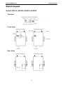
Panel Layout
OnCell G3111/G3151/G3211/G3251
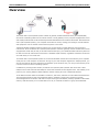
Top View
Front View
Rear View

OnCell G3000 Series Getting Started
2-3
Bottom Views
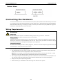
Connecting the Hardware
This section describes how to connect the OnCell G3111/G3151/G3211/G3251 cellular IP Gateway to a host PC
or serial device for first time testing purposes. We cover topics such as: Wiring Requirements, SIM Installation,
Wall and DIN-Rail Mounting, Connecting the Power, Connecting to a Serial Device, Adjustable Pull High/Low
Resistors for the RS-485 Port, and LED Indicators.
Wiring Requirements
ATTENTION
Safety First!
Be sure to disconnect the power cord before install
ing and/or wiring your device. The OnCell
G3111/G3151/G3211/G3251 should be secured at one location.
Wiring Caution!
Calculate the maximum possible current in each power wire and common wire. Observe all
electrical codes
dictating the maximum current allow
able for each wire size. If the current goes
above the maximum ratings,
the wiring could overheat, causing serious damage to your equipment.
Temperature Caution!
Be careful when handling the device. When plugged in, the device’s internal components
generat
e heat, and
consequently the casing may feel hot to the touch.
You should also heed the following guidelines:
• Use separate paths to route wiring for power and devices. If power wiring and device wiring paths must
cross, make sure the wires are perpendicular at the intersection point.
NOTE: Do not run signal or communication wiring and power wiring in the same wire conduit. To avoid
interference, wires with different signal characteristics should be routed separately.
• Use the type of signal transmitted through a wire to determine which wires should be kept separate. The
rule of thumb is that wiring that shares similar electrical characteristics can be bundled together.
• Keep input wiring and output wiring separate.
• Where necessary, it is advisable to label the wiring to all devices in the system.

OnCell G3000 Series Getting Started
2-4
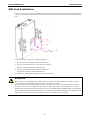
SIM Card Installation
In order to protect the SIM card, the SIM card slot is located inside the OnCell G3111/G3151/G3211/G3251’s
casing. You will need to unscrew and remove the outer SIM card cover before installing or removing the SIM
card.
Follow these steps to remove or install the SIM card:
1. Remove the screw holding the outer SIM card cover.
2. Push the outer SIM card cover to the down to remove it.
3. Rotate it upwards to expose the SIM card slot.
4. (a) Remove the SIM card from the SIM card slot, or
(b) Insert the SIM card into the SIM card slot.
5. Reverse the above steps to replace the outer SIM card cover.
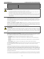
ATTENTION
If the modem is in GSM/GPRS mode, SIGNAL LEDs will not be illuminated
if the phone number or APN is
incorrect. Check the GSM
/GPRS LED if the SIM card is installed correctly.
The
GSM/GPRS LEDs on the front panel provide a convenient way of checking if the SIM card is installed
properly. If the antenna is installed and the net
work is operating normally, then at least one of the three
SIGNAL LEDs should be illuminated at all times. If none of the GSM
/GPRS and SIGNAL
LEDs are illuminated,
then the SIM card may not be installed properly. This is because the PIN code is stored on the SIM card; if the
PIN code cannot be accessed, then the modem will not be accessible over the network.

OnCell G3000 Series Getting Started
2-5
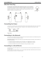
DIN-Rail Mounting
The OnCell G3111/G3151/G3211/G3251 gateways have built
-in “ears” for attaching
the IP Gateway to a wall or the inside of a cabinet.
We suggest using two screws per ear
to attach the IP Gateway to a wall or the inside of a cabinet. The heads of the screws
should be less than 6.0 mm in diameter, and the shafts should be less than 3.5 mm in
diameter, as shown in the figure at the right.
Connecting the Power
Connect the 12 to 48 VDC power cord with the OnCell G3111/G3151/G3211/G3251’s power input. If the power
is properly supplied, the “PWR” LED will glow a solid green color to indicate that the system is ready.
Connecting to the Network
Connect one end of the Ethernet cable to the OnCell G3111/G3151/G3211/G3251’s 10/100M Ethernet port and
the other end of the cable to the Ethernet network.
If the cable is properly connected, the OnCell G3111/G3151/G3211/G3251 will indicate a valid connection to
the Ethernet as follows:
• The Ethernet LED glows a solid green when connected to a 100 Mbps Ethernet network.
• The Ethernet LED glows a solid orange when connected to a 10 Mbps Ethernet network.
• The Ethernet LED flashes when Ethernet packets are being transmitted or received.
Connecting to a Serial Device
The OnCell G3111 and G3211 support one or two RS-232 port that connects through a DB9 male connector on
the bottom panel.
The OnCell G3151 and G3251 support one or two RS-232/RS-422/RS-485-4w/RS-485-2w port that connects
through a DB9 male connector on the bottom panel.

OnCell G3000 Series Getting Started
2-6
Adjustable Pull High/Low Resistors for the RS-485 Port
(G3151/G3251)
In some critical environments, you may need to add termination resistors to prevent the reflection of serial
signals. When using termination resistors, it is important to set the pull high/low resistors correctly so that the
electrical signal is not corrupted. Since a particular pull high/low resistor value cannot fit all environments, the
OnCell G3151/G3251 uses DIP switches to set the pull high/low resistor values for the serial port.
To set the termination resistor to 150 K
Ω
, make sure both of the assigned DIP switches are in the OFF
position. This is the default setting.
To set the termination resistor to 1 K
Ω
, make sure both of the assigned DIP switches are in the ON
position.
ATTENTION
Do
not use the 1 KΩ setting on the OnCell G3151/G3251 when using the RS-232 interface. Doing so will
degrade
the RS-232 signals and shorten the maximum allowed communication distance.
DIP switches on the bottom of the OnCell G3111/G3151/G3211/G3251 are used to set the pull high/low
resistor value for each serial port.
SW
1 2 3 4
Pull High Pull Low Terminator ---
ON 1 KΩ 1 KΩ 120 KΩ ---
OFF 150 KΩ 150 KΩ --- ---
Note: If the pull high/low resistor on your device is already set for RS-485, make sure the default
SW for RS-232 is “OFF” when you switch back to RS-232 interface.
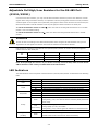
LED Indicators
The LED indicators on the front panel of the OnCell G3111/G3151/G3211/G3251 are described in the following
table.
Type Color LED Function
PWR
Green Activation of DC Power.
Off Power is off, or power error condition exists.
TX/RX
Green The serial port is transmitting data
Amber The serial port is receiving data.
Off No data is being transmitted or received through the serial port.
GSM/GPRS
Green GSM is connected.
Amber GPRS is connected.
Off GSM/GPRS is disconnected.
Ready
Green
Steady on: Software Ready.
Blinking slowly (1 sec): The OnCell has been located by Ready the OnCell
Search Utility.
Red
(Over Green)
Steady on: Booting up, or IP fault.
Blinking rapidly (0.5 sec): IP conflict.
Blinking slowly (1 sec): Cannot get an IP address from the DHCP server.
Off Booting up or there is no error condition.
Signal
(3 LEDs)
Green
Number of lit LEDs indicates signal level
(at least 2 LEDs must illuminated for data transmission)

OnCell G3000 Series Getting Started
2-7
ATTENTION
GSM/GPRS LED:
OFF: Cannot register with cellular providers using GSM/GPRS mode,
due to wrong PIN code, no cellular
provider available, wrong APN, or wrong username/password.
ON:
Registered with cellular provider using GSM/GPRS mode. GSM/GPRS Signal LEDs will be on.
Reset Button
Press and hold the Reset button for 5 sec to load factory defaults: Use a pointed object, such as a straightened
paper clip or toothpick, to press the reset button. This will cause the Ready LED to blink on and off. The factory
defaults will be loaded once the Ready LED stops blinking (default IP: 192.168.127.254).

3
3. Initial IP Address Configuration
When setting up the OnCell G3111/G3151/G3211/G3251 for the first time, the first thing you should do is
configure its IP address. This chapter introduces the different methods that can be used. Refer to Chapter 10,
System Management Settings, for more details about network settings.
The following topics are covered in this chapter:
Static and Dynamic IP Addresses
Factory Default IP Address
Configuration Options
OnCell Search Utility
Web Console
ARP
Telnet Console
Serial Console

OnCell G3000 Series Initial IP Address Configuration
3-2
Static and Dynamic IP Addresses
Determine whether your OnCell G3111/G3151/G3211/G3251 needs to use a static IP address or dynamic IP
address (either DHCP or BOOTP application).
• If your OnCell G3111/G3151/G3211/G3251 is used in a static IP environment, you must assign a
specific IP address using one of the tools described in this chapter.
• If your OnCell G3111/G3151/G3211/G3251 is used in a dynamic IP environment, the IP address
will be assigned automatically from over the network. In this case, set the IP configuration mode to DHCP
or BOOTP.
ATTENTION
Consult your network administrator on how to reserve a fixed IP address for your
OnCell
G3111/G3151/G3211/G3251
in the MAC-
IP mapping table when using a DHCP Server or BOOTP Server. For
most applications, you should assign a fixed IP address to your
OnCell G3111/G3151/G3211/G3251.
Factory Default IP Address
The OnCell G3111/G3151/G3211/G3251 is configured with the following default private IP address:
192.168.127.254
Note that IP addresses that begin with “192.168” are referred to as private IP addresses. Devices configured
with a private IP address are not directly accessible from a public network. For example, you would not be able
to ping a device with a private IP address from an outside Internet connection. If your application requires
sending data over a public network, such as the Internet, your OnCell G3111/G3151/G3211/G3251 will need
a valid public IP address, which can be leased from a local ISP.
Configuration Options
OnCell Search Utility
You may configure your OnCell G3111/G3151/G3211/G3251 with the bundled OnCell Search Utility for
Windows. Refer to Chapter 11, Software Installation/Configuration, for details on how to install and use OnCell
Search Utility.
Web Console
You may configure your OnCell G3111/G3151/G3211/G3251 using a standard web browser. Refer to Chapter
5, Using the Web Console, for details on how to access and use the OnCell G3111/G3151/G3211/G3251 web
console.

OnCell G3000 Series Initial IP Address Configuration
3-3
ARP
You may use the ARP (Address Resolution Protocol) command to set up an IP address for your OnCell
G3111/G3151/G3211/G3251. The ARP command tells your computer to associate the OnCell
G3111/G3151/G3211/G3251’s MAC address with an IP address. Afterwards, use Telnet to access the OnCell
G3111/G3151/G3211/G3251 and its IP address will be reconfigured.
ATTENTION
In order to use
the ARP setup method, both your compute
r and the OnCell G3111/G3151/G3211/G3251 must
be connected to the same LAN.
You may use an Ethernet cable to connect the OnCell
G3111/G3151/G3211/G3251
directly to your computer’s Ethernet card.
Before executing the ARP command,
y
our OnCell G3111/G3151/G3211/G3251 must be configured with the factory default IP address
(192.168.127.254) and your computer and the OnCell G3111/G3151/G3211/G3251
must be on the same
subnet.
To use ARP to configure the IP address, complete the following:
1. Obtain a valid IP address for your OnCell G3111/G3151/G3211/G3251 from your network administrator.
2. Obtain your OnCell G3111/G3151/G3211/G3251’s MAC address from the label on the bottom panel.
3. Execute the
arp -s command from your computer’s MS-DOS prompt as follows:
arp -s <IP address> <MAC address>
For example,
C:\> arp -s 192.168.200.100 00-90-E8-04-00-11
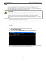
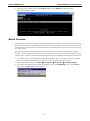
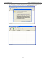
4. Next, execute a special Telnet command by entering the following exactly:
telnet 192.168.200.100 6000
When you enter this command, a Connect failed message will appear, as shown below.
5. After the OnCell G3111/G3151/G3211/G3251 reboots, its IP address will be assigned to the new address
and you can reconnect using Telnet to verify that the update was successful.

OnCell G3000 Series Initial IP Address Configuration
3-4
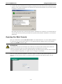
Telnet Console
Depending on how your computer and network are configured, you may find it convenient to use network
access to set up your OnCell G3111/G3151/G3211/G3251’s IP address. This can be done using Telnet.
ATTENTION
Figures in this section were taken from
the OnCell G3111/G3151/G3211/G3251’s Telnet console.
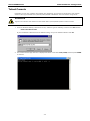
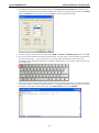
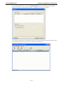
1. From the Windows desktop, select Start Run, and then type the following content in the Run window:
telnet 192.168.127.254
If your IP address is different from the default setting, use your IP address instead. Click OK.
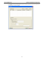
2. The console terminal type selection is displayed as shown. Enter 1 for ansi/vt100, and then press ENTER
to continue.

OnCell G3000 Series Initial IP Address Configuration
3-5
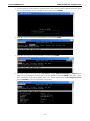
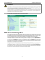
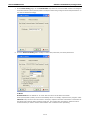
3. The following page will only appear if the OnCell G3111/G3151/G3211/G3251 is password protected. Enter
the console password if you are prompted to do so, and then press ENTER.
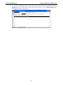
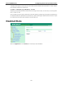
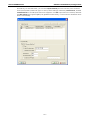
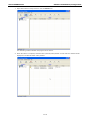
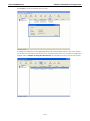
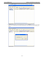
4. Press N or use the arrow keys to select Network, and then press ENTER.
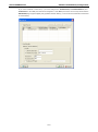
5. Press B or use the arrow keys to select Basic, and then press ENTER.
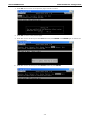
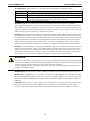
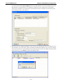
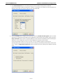
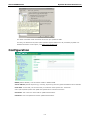
6. Use the arrow keys to move the cursor to IP address. Use the DELETE, BACKSPACE, or SPACE keys to
erase the current IP address, and then type in the new IP address and press ENTER. Note that if you are
using a dynamic IP configuration (BOOTP, DHCP, etc.), you will need to go to the IP configuration field
and press ENTER to select the appropriate configuration.
La pagina si sta caricando...
La pagina si sta caricando...
La pagina si sta caricando...
La pagina si sta caricando...
La pagina si sta caricando...
La pagina si sta caricando...
La pagina si sta caricando...
La pagina si sta caricando...
La pagina si sta caricando...
La pagina si sta caricando...
La pagina si sta caricando...
La pagina si sta caricando...
La pagina si sta caricando...
La pagina si sta caricando...
La pagina si sta caricando...
La pagina si sta caricando...
La pagina si sta caricando...
La pagina si sta caricando...
La pagina si sta caricando...
La pagina si sta caricando...
La pagina si sta caricando...
La pagina si sta caricando...
La pagina si sta caricando...
La pagina si sta caricando...
La pagina si sta caricando...
La pagina si sta caricando...
La pagina si sta caricando...
La pagina si sta caricando...
La pagina si sta caricando...
La pagina si sta caricando...
La pagina si sta caricando...
La pagina si sta caricando...
La pagina si sta caricando...
La pagina si sta caricando...
La pagina si sta caricando...
La pagina si sta caricando...
La pagina si sta caricando...
La pagina si sta caricando...
La pagina si sta caricando...
La pagina si sta caricando...
La pagina si sta caricando...
La pagina si sta caricando...
La pagina si sta caricando...
La pagina si sta caricando...
La pagina si sta caricando...
La pagina si sta caricando...
La pagina si sta caricando...
La pagina si sta caricando...
La pagina si sta caricando...
La pagina si sta caricando...
La pagina si sta caricando...
La pagina si sta caricando...
La pagina si sta caricando...
La pagina si sta caricando...
La pagina si sta caricando...
La pagina si sta caricando...
La pagina si sta caricando...
La pagina si sta caricando...
La pagina si sta caricando...
La pagina si sta caricando...
La pagina si sta caricando...
La pagina si sta caricando...
La pagina si sta caricando...
La pagina si sta caricando...
La pagina si sta caricando...
La pagina si sta caricando...
La pagina si sta caricando...
La pagina si sta caricando...
La pagina si sta caricando...
La pagina si sta caricando...
La pagina si sta caricando...
La pagina si sta caricando...
La pagina si sta caricando...
La pagina si sta caricando...
La pagina si sta caricando...
La pagina si sta caricando...
La pagina si sta caricando...
La pagina si sta caricando...
La pagina si sta caricando...
La pagina si sta caricando...
La pagina si sta caricando...
La pagina si sta caricando...
La pagina si sta caricando...
La pagina si sta caricando...
La pagina si sta caricando...
La pagina si sta caricando...
La pagina si sta caricando...
La pagina si sta caricando...
La pagina si sta caricando...
La pagina si sta caricando...
La pagina si sta caricando...
La pagina si sta caricando...
La pagina si sta caricando...
La pagina si sta caricando...
La pagina si sta caricando...
La pagina si sta caricando...
La pagina si sta caricando...
La pagina si sta caricando...
La pagina si sta caricando...
La pagina si sta caricando...
La pagina si sta caricando...
La pagina si sta caricando...
La pagina si sta caricando...
La pagina si sta caricando...
La pagina si sta caricando...
La pagina si sta caricando...
La pagina si sta caricando...
La pagina si sta caricando...
La pagina si sta caricando...
La pagina si sta caricando...
La pagina si sta caricando...
La pagina si sta caricando...
La pagina si sta caricando...
La pagina si sta caricando...
La pagina si sta caricando...
La pagina si sta caricando...
La pagina si sta caricando...
La pagina si sta caricando...
La pagina si sta caricando...
La pagina si sta caricando...
La pagina si sta caricando...
La pagina si sta caricando...
La pagina si sta caricando...
La pagina si sta caricando...
La pagina si sta caricando...
La pagina si sta caricando...
La pagina si sta caricando...
-
 1
1
-
 2
2
-
 3
3
-
 4
4
-
 5
5
-
 6
6
-
 7
7
-
 8
8
-
 9
9
-
 10
10
-
 11
11
-
 12
12
-
 13
13
-
 14
14
-
 15
15
-
 16
16
-
 17
17
-
 18
18
-
 19
19
-
 20
20
-
 21
21
-
 22
22
-
 23
23
-
 24
24
-
 25
25
-
 26
26
-
 27
27
-
 28
28
-
 29
29
-
 30
30
-
 31
31
-
 32
32
-
 33
33
-
 34
34
-
 35
35
-
 36
36
-
 37
37
-
 38
38
-
 39
39
-
 40
40
-
 41
41
-
 42
42
-
 43
43
-
 44
44
-
 45
45
-
 46
46
-
 47
47
-
 48
48
-
 49
49
-
 50
50
-
 51
51
-
 52
52
-
 53
53
-
 54
54
-
 55
55
-
 56
56
-
 57
57
-
 58
58
-
 59
59
-
 60
60
-
 61
61
-
 62
62
-
 63
63
-
 64
64
-
 65
65
-
 66
66
-
 67
67
-
 68
68
-
 69
69
-
 70
70
-
 71
71
-
 72
72
-
 73
73
-
 74
74
-
 75
75
-
 76
76
-
 77
77
-
 78
78
-
 79
79
-
 80
80
-
 81
81
-
 82
82
-
 83
83
-
 84
84
-
 85
85
-
 86
86
-
 87
87
-
 88
88
-
 89
89
-
 90
90
-
 91
91
-
 92
92
-
 93
93
-
 94
94
-
 95
95
-
 96
96
-
 97
97
-
 98
98
-
 99
99
-
 100
100
-
 101
101
-
 102
102
-
 103
103
-
 104
104
-
 105
105
-
 106
106
-
 107
107
-
 108
108
-
 109
109
-
 110
110
-
 111
111
-
 112
112
-
 113
113
-
 114
114
-
 115
115
-
 116
116
-
 117
117
-
 118
118
-
 119
119
-
 120
120
-
 121
121
-
 122
122
-
 123
123
-
 124
124
-
 125
125
-
 126
126
-
 127
127
-
 128
128
-
 129
129
-
 130
130
-
 131
131
-
 132
132
-
 133
133
-
 134
134
-
 135
135
-
 136
136
-
 137
137
-
 138
138
-
 139
139
-
 140
140
-
 141
141
-
 142
142
-
 143
143
-
 144
144
-
 145
145
-
 146
146
-
 147
147


Moxa OnCell G3101/G3201 Series Manuale utente
- Categoria
- Software di gestione della rete
- Tipo
- Manuale utente
in altre lingue
Documenti correlati
Altri documenti
-
Christie LX1750 Manuale utente
-
Planet RT-101 Manuale utente
-
Digicom Serial Server Manuale utente
-
-
Electrolux CONTROLBOX 24/7 Manuale utente
-
Omega IC-11 Series Manuale del proprietario
-
 Western Telematic CAS-81 Manuale utente
-
Monnit Alta 4G LTE Cellular Gateway Guida utente
-
 Sonder TELKAN 1 GSM Manual Of Installation And Use
-
Eurotherm 4001 Manuale del proprietario

