Munters Counterweight Manuale del proprietario
- Tipo
- Manuale del proprietario

1© Munters Corporation, July 2017
QM1165r6
Instruction Manual
COUNTERWEIGHT KIT
for Air Actuated Baffl e
Models: BCW-4P
COUNTERWEIGHT
KIT
for Air Actuated
Baffl e

© Munters Corporation, July 2017
2
QM1165r6
BCW-4P Manual for use and Maintenance
Thank You:
Thank you for purchasing a Munters Counterweight Kit. Munters equipment is designed to be the highest
performing, highest quality equipment you can buy. With the proper installation and maintenance it will provide
many years of service.
Please Note:
To achieve maximum performance and insure long life from your Munters product it is essential that it be installed
and maintained properly. Please read all instructions carefully before beginning installation.
Warranty:
For Warranty claims information see the “Warranty Claims and Return Policy” form QM1021 available from the
Munters Corporation office at 1-800-227-2376 or by e-mail at [email protected].
Conditions and Limitations:
• Products and Systems involved in a warranty claim under the “Warranty Claims and Return Policy” shall have
been properly installed, maintained and operated under competent supervision, according to the instructions
provided by Munters Corporation.
• Malfunction or failure resulting from misuse, abuse, negligence, alteration, accident or lack of proper installation
or maintenance shall not be considered a defect under the Warranty.

3© Munters Corporation, July 2017
QM1165r6
Index
Chapters Page
1. Unpacking the Equipment 4
1.1 Parts List 4
1.2 Part Dimensions 4
2. Installation Instructions 5
2.1 Installation for CI0896-R and CI1296-R 5
2.2 Installation for adapting 890P and 1290P 8
3. Adjustment 9

© Munters Corporation, July 2017
4
QM1165r6
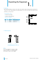
1.1 Parts List
Unpacking the Equipment
1.
Before beginning installation, check the overall condition of the equipment. Remove packing materials, and examine all
components for signs of shipping damage. Any shipping damage is the customer's responsibility and should be reported
immediately to your freight carrier.
1.2 Part Dimensions
Each BCW-4P includes:
1 - AC1512 Counterweight
1 - Hardware Package (HP1033)
COUNTERWEIGHT, AC1512
Front View Side View
Note:
The Counterweight Kit is designed to adapt
plastic Aero-Baffle for air actuated operation.
Use two kits for each 8’ section of baffle.
HP1033 for BCW-4P
ID Qty. Cat. No. Description
[A] 1 KX2802
1
⁄4”-20 x2” U-Bolt, SS
[B] 2 KN2301
1
⁄4”-20 Wing Nuts, NY
[C] 2 KW3002
1
⁄4” Washers, SS

5© Munters Corporation, July 2017
QM1165r6
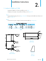
Installation Instructions
2.
Step 1
Construct a framed opening as shown in Figures 1A and 1B. Each open end of the baffle needs a framed end
gusset. See Figure 1C.
Step 2
Position and secure in place a length of
1
⁄4-R
ound trim board for baffle stop. See Figure 1A.
Figure 1A
CROSS SECTION
Figure 1B
FRONT VIEW
End Gusset
Figure 1C
SIDE VIEW
2.1 Installation for CI0896-R and CI1296-R
If installing for CI0896-R or CI1296-R Aero-Baffle, proceed to Step 1.
If adapting counterweight to existing 890P and 1290P, proceed to Steps 13-17.
1
⁄8”
1
⁄8”
1
⁄4-Rou
nd Primed
and Painted.
1
⁄4-Rou
nd
Primed and
Painted.
Table 1

© Munters Corporation, July 2017
6
QM1165r6
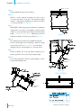
Installation InstructionsChapter 2
Step 3
Prime and paint all exposed wood surfaces.
Step 4
Drill (2)
9
⁄32” holes, centered on length of door for a 4’ door
or 2’ from each end for an 8’ door. The first hole should be
located
1
⁄2” down from top of baffle and second hole should be
1
1
⁄2” from top of baffle. See Figure 2.
Step 5
Attach baffle to framed opening using aluminum or galvanized
roofing nails or screws (do not overtighten). Mount top edge
of hinge
5
⁄8” up on top header and centered on framed opening
length. See Figure 3A, 3B & 3C. Baffle may need to be
trimmed to maintain end clearance specified in Figure 3C.
Step 6
Insert U-Bolt [A], from exhaust side of baffle through holes.
Position counterweight slot over U-Bolt legs.
Make sure weight
is positioned as shown in
Figure 3A & 3B. Recommended
starting position for counterweight is 3
1
⁄2” from top of door.
Step 7
Install one Washer [C] on top leg and two Washers [C] on
bottom leg of U-Bolt. Fasten in place with (2) Wing Nuts
[B].
Step 8
Loosen Wing Nuts [B] to slide the counterweight up or down
to desired operating position.
1
1
⁄2”
1
⁄2”
Drill (2)
9
⁄32” holes
Figure 2
1
⁄2” down
from top of
baffle
1
1
⁄2” down from
top of baffle
5
⁄8”
Figure 3A
Figure 3B
CROSS SECTION
1
⁄4-Rou
nd Primed
and Painted.
5
⁄8”
3
1
⁄
2
”
Figure 3C
1
⁄16”
1
⁄8”

7© Munters Corporation, July 2017
QM1165r6
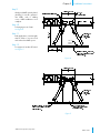
Installation InstructionsChapter 2
Figure 4
Figure 5
Step 9
Gently push baffle open by hand,
checking for smooth operation.
Trim baffle ends if rubbing
occurs. Baffle installation is now
complete.
Step 10
For bringing air out of attic.
See Figure 4.
Step 11
In this application, counterweights
must be offset so as not to touch
each other when baffle opens.
Step 12
For support of air take off board.
See Figure 5.
1
⁄4-Rou
nd
Primed and
Painted.

© Munters Corporation, July 2017
8
QM1165r6
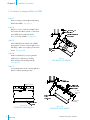
2.2 Installation for adapting 890P and 1290P
Figure 6
OLD BAFFLE, OLD WEIGHT
5
⁄8”
Figure 7B
OLD BAFFLE, NEW WEIGHT
Step 13
Remove existing counterweight and mounting
bracket from baffle. See Figure 6.
Step 14
Drill (2)
9
⁄32” holes, centered on length of door.
The first hole should be located
1
⁄2” down from
top of baffle and second hole should
be 1
1
⁄2” from top of baffle. See Figure 7A.
Step 15
Insert U-Bolt [A], from exhaust side of baffle,
through holes. Position counterweight slot over
U-Bolt legs. Make sure weight is positioned as
shown. See Figure 7B.
Step 16
Install one Washer [C] on top leg and two
Washers [C] on bottom leg of U-Bolt,
fasten in place with (2) Wing Nuts [B].
See Figure 7B.
Step 17
Loosen Wing Nuts to slide counterweight up or
down to desired operating position
Figure 7A
OLD BAFFLE, NEW WEIGHT
1
⁄2” down
from top of
baffle
1
1
⁄2” down from
top of baffle
1
1
⁄2”
1
⁄2”
Drill (2)
9
⁄32” holes
5
⁄8”
Installation InstructionsChapter 2

9© Munters Corporation, July 2017
QM1165r6
Adjustment
3.
Step 1
To achieve a higher static pressure in room, lower
counterweight slightly.
Step 2
To achieve a lower static pressure in room, raise
counterweight slightly.

© Munters Corporation, July 2017
10
QM1165r6
Munters Europe AB, Isafjordsgatan 1, P.O. Box 1150, SE-164 26 Kista, Sweden. Phone +46 08 626 63 00, Fax +46 8 754 56 66.
Munters Corporation 2691 Ena Drive Lansing, MI 48917 U.S.A. Phone +1 800-227-2376, Fax +1 517-676-7078
www.munters.us
Australia Munters Pty Limited, Phone +61 2 6025 6422, Brazil Munters Brasil Industria e Comercio Ltda, Phone +55 41 3317 5050, Canada/US Munters
Corporation Lansing, MI Phone +1 517 676 7070, China Munters Air Treatment Equipment (Beijing) Co. Ltd, Phone +86 10 80 481 121, Denmark Munters A/S,
Phone +45 9862 3311,
India Munters India, Phone +91 20 3052 2520, Indonesia Munters, Phone +62 818 739 235, Italy Munters Italy S.p.A., Chiusavecchia,
Phone +39 0183 52 11, Japan Munters K.K., Phone +81 3 5970 0021, Korea Munters Korea Co. Ltd., Phone +82 2 761 8701, Mexico Munters Mexico, Phone
+52 818 262 54 00, Russia Munters AB, Phone +7 812 448 5740, Singapore Munters Pte Ltd., Phone +65 744 6828, South Africa and Sub-Sahara Countries
Munters (Pty) Ltd., Phone +27 11 997 2000, Spain Munters Spain S.A., Phone +34 91 640 09 02, Sweden Munters AB, Phone +46 8 626 63 00, Thailand
Munters Co. Ltd., Phone +66 2 642 2670, Turkey Munters Form Endüstri Sistemleri A.Ş, Phone +90 322 231 1338, USA Munters Corporation Lansing, MI Phone
+1 517 676 7070, Vietnam Munters Vietnam, Phone +84 8 3825 6838, Export & Other countries Munters Italy S.p.A., Chiusavecchia Phone +39 0183 52 11
Counterweight Kits are developed and produced by Munters Corporation, Lansing, Michigan U.S.A. 1-800-227-2376
-
 1
1
-
 2
2
-
 3
3
-
 4
4
-
 5
5
-
 6
6
-
 7
7
-
 8
8
-
 9
9
-
 10
10


Munters Counterweight Manuale del proprietario
- Tipo
- Manuale del proprietario
in altre lingue
- English: Munters Counterweight Owner's manual
Documenti correlati
-
Munters BI28SPM Manuale del proprietario
-
-
-
-
-
-
-
-
-