
Installation manual
Manuale di installazione
WDP
Gutter system
Sistema di distribuzione dell'acqua
WDP
Ag/MIT/UmGb-2216-10/14 rev 1.0

2
© Munters AB, 201
8
Munters reserves the right to make alterations to specifications, quantities, dimensions etc. for production
or other reasons subsequent to publication.
The information contained herein has been prepared by qualified experts within Munters. While we
believe the information is accurate and complete, we make no warranty or representation for any particular
purpose. The information is offered in good faith and with the understanding that any use of the units or
accessories in breach of the directions and warnings in this document is at the sole discretion and risk of
the user.

3
© Munters AB, 2018
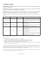
Contents
1. General 4
1.1 Disclaimer 4
1.2 Introduction 4
1.3 Notes 4
2. Before using 5
2.1 Delivery check 6
2.2 Packaging and transport 6
2.3 Typical installations 6
3. Installation 7
3.1 Mounting the brackets 7
3.2 Assembling the bottom gutter 9
3.3 Mounting the sides 10
3.4 Assembling the top gutter 11
3.5 Inserting the drains 12
3.6 Inserting the CELdek
®
pads 13
3.7 Double "T" profile for Celdek
®
pads overlapping 14
3.8 Water distribution components 15
3.9 Plumbing kit components for the distribution pipes 17
4. Commissioning 19
4.1 First time start up 19
4.2 Setting the bleed-off rate 19
4.3 Trouble shooting 20
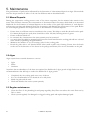
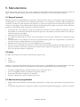
5. Maintenance 21
5.1 Mineral deposits 21
5.2 Algae 21
5.3 Regular maintenance 21
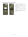
5.4 Replacement of a CELdek
®
pad 22
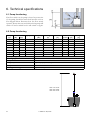
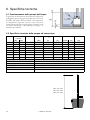
6. Technical specifications 23
6.1 Pump functioning 23
6.2 General 23
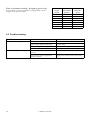
6.3 Water tank 24

4
© Munters AB, 2018
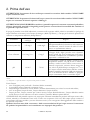
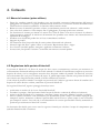
1. General
1.1 Disclaimer
Munters reserves the right to make alternations to specifications, quantities, dimensions etc. for production or
other reasons, subsequent to publication.
The information contained herein has been prepared by qualified experts within Munters.
While we believe the information is accurate and complete, we make no warranty or representation for any
particular purposes. The information is offered in good faith and with the understanding that any use of the
units or accessories in breach of the directions and warnings in this document is at the sole discretion and risk
of the user.
Any complaints concerning the products are conditioned by the strict compliance of the instructions contained
by the manual. The manufacturer reserves the right to forfeit any claims e.g. corrosion resulting from non-
observance of the instructions and non-compliant use e.g. proper bleed-off.
1.2 Introduction
Congratulations on your excellent choice of purchasing a Munters WDP gutter system!
In order to realise the full benefit from this product it is important that it is installed, commissioned and
operated correctly. Before installation or using the WDP gutter system, this manual should be studied carefully.
It is also recommended that it is kept safely for future reference.
The manual is intended as a reference for installation, commissioning and day-to-day operation of the Munters
WDP gutter system.
1.3 Notes
Date of release: April 2014.
Munters cannot guarantee to inform users about changes or to distribute new manuals to them.
All rights reserved. No part of this manual may be reproduced in any manner whatsoever without the expressed
written permission of Munters.
The contents of this manual are subject to change without notice.
WARNING!
• All the components and spare parts MUST be stored in dry and clean
environment
• Max environment temperature during assembling and/or storage shall not
exceed 50°C.
• DO NOT stock packages under direct sunrays.

5
© Munters AB, 2018
2. Before using
WARNING! The presence of Chlorine in the water will cause corrosion to the Gutter. DO NOT USE
water containing Chlorine.
WARNING! The presence of Chlorides in the water will cause corrosion to the Gutter. DO NOT
USE water having Chlorides content higher than 200mg/l.
WARNING! Do not expose the gutter system to substances containing barium polysulfide
(insecticides, pesticides and fungicides) as irreversible damage may occur to the gutter system.
Please note the limits for make-up water and sump water at ambient temperature for evaporative cooling
systems.
Constituent Make-up* Water Sump ** Water Reasons
Chlorides (as Cl) <50 mg/l <200 mg/l
High Chlorides will cause corrosion of metal
parts. Chlorides are contributed by contaminants
such as sodium chloride. Chlorine is a minor
contributor
Chlorine or
Bromine
0-1.5 mg/l *** 0 mg/l
Chlorine and bromine will rarely control algae
because they are
both very volatile and will not stay in the water.
Both will turn
Munters pads soft and shorten their life.
pH 6.0-8.5 7.0-9.0
Low pH is acid and will cause the paper to be
brittle. High pH is
more like lye and causes the paper to become
fluffy like cotton.
Pads will last the longest with a pH of 7 to 9. If
the water absorbs
ammonia from the air drawn across the pads,
the pH can increase to as high as 10.5. Bleed off
definitely helps to control pH.
*) Make-up water is the water supply needed to replace the water which is lost by evaporation in a closed-circuit gutter system;
**) Sump water is the water found in the covered tank or cistern;
Sources of water:
• Deep wells or municipal water supplies are recommended;
• ***) Chlorinated municipal make-up water is not recommended for spray on pads;
• Lake and river water should be filtered and chemically treated for microbial growth;
• Seawater, brackish water and reclaimed water are not recommended;
• Rainwater, reverse osmosis water, demineralized water and zeolite softened water should be used with
caution. Consult Munters before using.
Note: only pure water evaporates from the evaporative cooling pads. Naturally occurring components such
as sodium and chlorides, minerals and contaminants such as sulfur or barium present in the water, do not
evaporate. Over the time, as these substances concentrate in the remaining water, they can become harmful
resulting in damaging the gutter system and the evaporative cooling pads.
Any disregard of the above warnings and recommendations shall exonerate the manufacturer from any liability
and shall be considered improper use of the gutter system.

6
© Munters AB, 2018
2.1 Delivery check
Upon receipt, inspect the item for external damage and if found, inform the forwarding agent without delay.
Check the data on all the rating plates of the pumps, especially voltage and frequency.
2.2 Packaging and transport
Since the gutter segments consist of numerous long pieces, care should be taken when the pieces are handled
and stored. If the pieces are placed on a heap, the sides of the heap should be supported to prevent the heap
from collapsing and causing injury.
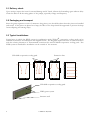
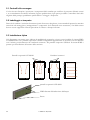
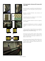
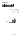
2.3 Typical installations
Typical ways in which the WDP system in combination with CELdek
®
evaporative cooling pads can be
installed in structures are indicated in the diagrams below. The diagrams depict structures as seen from above
with the relative placement of Euroemme
®
extraction fans and CELdek
®
evaporative cooling pads. The
WDP system is intended for installation on the outside of the structure.
CELdek
®
evaporative cooling pads
Extraction fans
CELdek
®
evaporative cooling pads
WDP gutter system
Structure wall

7
© Munters AB, 2018
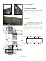
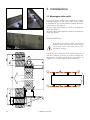
3. Installation
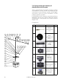
3.1 Mounting the brackets
The gutter sections are manufactured in five different
lengths, 3m, 2.4, 1.8, 1.2 and 0.6m. An installation
can be compiled by using different combinations
of the lengths. Use Diagram 1 to decide on the
placement of the various lengths of gutter.
Mount each bottom bracket using q.ty 2, Ø8 Fisher.
Mount each top bracket using q.ty 2,Ø6 Fisher.
ALIGNMENT!
Verify the distance between the top and bottom
brackets continuously. Place the bottom support
gutter every meter and the top gutter support where
it is required.
Ensure that all the top brackets and a the
bottom brackets are mounted on the same
horizontal level. Use a spirit-level or other
suitable device. (see pictures on side)
H+212

8
© Munters AB, 2018
Gutter sections
Available lengths: 0.6 m – 1.2 m – 1.8 m – 2.4 m – 3.0 m
It is recommended to use as many as possible 3.0 m sections, than complete the required length with a shorter
cut on size section.
Please note that total length must be a multiple of 0.6 m.
Examples:
1. total length 12 m: use q.ty 4 sections with 3.0 m length;
2. total length 16.8 m: use q.ty 5 sections with 3.0 m length and q.ty 1 section with 1.8 m length.
Water supply and drain
Using 0.75 hp pump on 100 mm thick evaporative pad it is suggested to place a water supply every 24 m and
a water drain every 12 m.
Using 0.75 hp pump on 150 mm thick evaporative pad it is suggested to place a water supply every 16 m and
a water drain every 12 m.
If several water connections are required, divide distance between them uniformly.
q.ty 2 water connections L/4 L/2 L/4
q.ty 3 water connections L/6 L/3 L/3 L/6
q.ty 4 water connections L/8 L/4 L/4 L/4 L/8
Diagram 1

9
© Munters AB, 2018
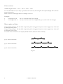
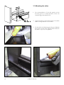
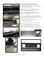
3.2 Assembling the bottom gutter
Join the section of the
bottom gut
ter, then start
applying silicon in correspondence of the holes. Fix the
bottom gutter using q.ty 6, M6 x 16 hex screws and its
nuts.
Apply silicon to the groove on the bottom gutter as
indicated in the picture on the left. Do it for both sides
of the gutter.
To ensure a watertight seal, apply silicon to both the inside
and outside of the gutter and spread it.
Once the whole bottom gutter length has been
assembled and the silicon cured, wash any debris out by
using water. Lock it on its support as shown in the
picture.
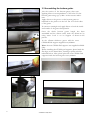
In the 150mm thickness gutter add the extra
CELdek
®
Pad support supplied every 600mm.
Note: the new CELdek Pad supports are supplied unfolded
(flat).
Before installing the CELdek pad supports, please bend the
flat edges on the dotted lines, forming a square cube like
indicated below. After, please place the extra CELdek Pad
supports inside the bottom gutter every 600mm.

10
© Munters AB, 2018
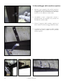
3.3 Mounting the sides
1. In correspondence of the side panels cut the
bottom gutter at 30mm distance from the
external edge, then bend it flat.
2. Apply the silicon on the bottom part of the sides
and in correspondence of the holes.
3. Fix the side to the bottom gutter by q.ty 6, M6x16
hex-screws and its nuts. Tighten bolts and nuts
by mean of q.ty 2, Ø 10 spanner.

11
© Munters AB, 2018
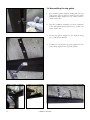
3.4 Assembling the top gutter
1. Join each top gutter support sliding into the top
side gutter groove then fix them to the water
distribution pipe support by q.ty 1,M6 x 16 hex-
screw and its nut.
2. Join the complete assembly you have obtained
to the side panels (both sides) by q.ty 1, M6 x 30
screw and its nut.
3. Fix the top gutter support to the wall by using
q.ty 2, Ø6 screw anchors.
4. Continue to secure the top gutter support to the
wall joining togheter the top side panels.

12
© Munters AB, 2018
3.5 Inserting the drains
Use Diagram 1 to decide on the placement of the
drains.
There should be one drain every 12m in 100mm
gutter thickness and every 12m in 150mm gutter
thickness.
Once the positions of the drains have been identified,
drill holes of ø 60 mm into the bottom gutter.
Put the rubber gasket on the threaded spout, then
insert the spout in the hole of the bottom gutter and
tight it in it's position by screwing the threaded ring
placed on the other side of gutter.

13
© Munters AB, 2018
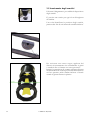
3.6 Inserting the CELdek
®
pads
Shake every pad and distributor before inserting in
order to remove dust.
Insert the CELdek
®
as indicated in the picture on
the left.
Ensure that all pads are moved tightly together once
inserted.
Insert the distributor pad from the top side as
indicated.
Ensure that the vertical alignment between the
CELdek
®
and the gutters is in line as indicated.
The last pad and distributor may need to be trimmed.
Use a saw if trimming is required.
Place the top side gutter onto the distributor pad
and join it to water distribution pipe support by q.ty
1, M6 x 30crew and its nut.
Join each top side gutter as previously described. Fix
the complete assembled you have obtained to the
side panel by q.ty 1, M6 x 30 screw and its nut.
Right Wrong

14
© Munters AB, 2018
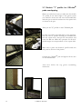
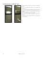
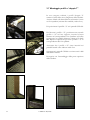
3.7 Double "T" profile for CELdek
®
pads overlapping.
When you order these item you will recive the double
"T" profile in the same lenght of the gutter system
you asked for. Screw the nut into the threaded bar
and than put in with the washer into the square hole
as shown in the pict.
Then put the "T" profile on the CELdek
®
pad.
In order to lock the T profile place on the opposite
side the other T profile inserting the threaded bar
into the square hole, then put the Ø6 washer and
screw the M6 nut. Make this operation for all the T
profile lenght in correspondence of the square hole.
Make sure to place the double T profile inside the
side panel as shown in the picture.
Overlap the CELdek
®
pad and tighten all the nuts
of the threaded bar.
After that follow the top gutter assembling
instruction.

15
© Munters AB, 2018
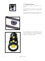
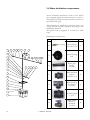
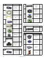
3.8 Water distribution components.
All the threaded connections need to have Teflon
tape wrapped tightly around the thread to ensure a
watertight seal, while sleeved connections need to be
glued with PVC glue.
The plastic pipe is supplied in 2 sections. One is 1m
T long and the second is supplied according to the
installation demands.
The plastic tube is supplied in 1 section of 1,8m
long.
Plumbing kit components
1
2
3
4
5
6
7
5
5
9
10
11
15
10 11 12 13 14
16
17
12
14 13
13
12
12 11
115
5
18
19
1920
20
8
Pos. Pict. Description Q.ty
2
Alimentation
brass valve 1/2"
1
3
Plastic floating
ball
1
6
Plastic pipe
DN40
L=1000
1
5
Male threaded
adaptor
40x50x1.1/4
3
9
Male threaded
tee adaptor
1.1/4 FFF
1
10
Threaded nipple
1.1/4"
2
11
Single union
valve F/F
threaded
1.1/4FF
2

16
© Munters AB, 2018
Pos. Pict.
Description
Q.ty
12
Threaded hose
adaptor 1.1/4x4°
2
13
Metal clamp
40/63
3
14
Spiralled pipe
D40
1,8
17
Solvent cement
hose adaptor
40x40
1
-
PVC cement
glue
1
-
PTFE tape
2
16
Solvent cement
double socket
1
15
Plastic pipe
L1000 for h1500 wdp
L1500 for h2000 wdp
L2000 for h3000 wdp
1
18
Male threaded
tee adaptor
40x40x1.1/4"
FFF
1
Pos. Pict. Description Q.ty
12
Threaded
hose adaptor
1.1/4"x40
2
Plunbing kit components for distribution pipes.
19
Plastic pipe
DN40
L=200
2
5
Male theaded
adaptor
40x50x1.1/4"
2
11
Single union valve
F/F threaded
1.1/4"FF
2
-
PTFE tape
2
Water distribution plastic pipe.
Pos. Pict. Description Q.ty
20
Water distribution
pipe
1
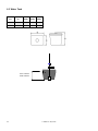
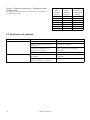
Pos. Pict. Description Q.ty
1
Water tank
1
7
Water tanl lid
1
8
Trap door
1
4
Pump
1
Pump and tank.

17
© Munters AB, 2018
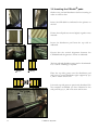
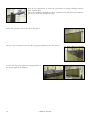
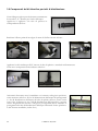
3.9 Plumbing kit components for distribution pipes
Using exploded view to rightly select the "T" piece
with threaded central for the water supply.
Put the seal into the plastic pipe in correspondence
of its groove.
Scratch the thread before wrapping the teflon tape around it.
Make sure to place the all assembling you have obtained in the right position
as shown in the picture with the water supply hole of the hose adaptor and the
water distribution hole of the plastic pipe top oriented. Connect the water
distribution pipe in order to cover the system length. Connect the plumbing
kit hose adaptor to the water distribution pipes hose adaptor as shown in the
picture by mean of q.ty 1, plastic tube and q.ty 2 metal pipe.
Apply the PVC cement glue around the plastic pipe and spread it.
Join all the components as shown in the picture.

18
© Munters AB, 2018
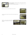
Join all the components as shown in the pictures by using teflontape and the
PVC cememt glue.
Insert the complete assemble you have obtained in the side panel hole and then
put it into the water distribution pipe.
Make this operation for both side of the gutter.
Put the top cover gutter onto the side top gutter pushing it into the groove.
Cut the two top cover gutter in correspondence to
the water supply hose adaptor.

19
© Munters AB, 2018
4. Commissioning
4.1 First time start up
• After the gutter, pads and plumbing kit have been installed, connect the fresh water supply to the float
valve in the tank and the pump to the electrical supply. The electrical connections should be done by a
qualified electrician according to local laws and regulations.
• Remove any visible material from the tank and the gutter.
• Open the water supply to the tank.
• Remove the drain pipes from the tank.
• Once the tank has filled to the float valve, the pump can be started.
• Let the system run for at least 15 minutes with the drain pipes still not connected to the tank. This will
clean debris that might have been left in the system during the installation process.
• Make a note of any leaks that might have occurred.
• Switch the pump off.
• Let all the water drain from the drain pipes before they are replaced into the tank.
• Unscrew the cap of the filter and clean the filament if necessary. Replace both the filament and the cap
• If there were any leaks, dry the places where the leaks occurred and re-seal.
• If necessary, start the system again an check again for any leaks.
4.2 Setting the bleed-off rate
The bleed-off rate is the water flow that needs to be constantly drained off to keep the mineral concentration
in the water to an optimal level. Too little bleed-off means too much scaling and clogging, resulting in frequent
pad change. Too much bleed-off results in high water costs. It is therefore important to calculate the optimal
bleed-off rate to get a long lasting pad with high performance.
As a good starting value, use 0.2l/minute/running meter of gutter. If scaling becomes apparent, increase the
amount of bleed-off.
To adjust the bleed-off, follow the steps listed below:
• place a 10l bucket underneath the outlet of the bleed-off;
• start the pump and allow it to run until the return water starts flowing into the tank;
• open the bleed-off valve and start measuring the time and continue to measure the time until the bucket
is filled;
• use the table below as a quick guideline of how long it should take to fill the bucket with water. Adjust
the opening of the valve more or less according to how long it has taken to fill the bucket. Once the right
opening size for the valve is determined, keep the valve at this position to ensure constant bleed-off.
As an alternative to the table, the following formula can be used to calculate the filling time for any size
container.

20
© Munters AB, 2018
Gutter
length
[meter]
Total bleed-
off required
[l/hour]
Time to fill a
10l bucket
[min]
6 75.0 8
9 112.5 5½
12 150.0 4
15 187.5 3¼
18 225.0 2¾
21 262.5 2½
24 300.0 2
4.3 Trouble shooting
Problem Possible fault Corrective action
No water circulating Pump doesn’t work Check electrical connection
Not enough water in the tank Fill the tank
Water entry joint not opened Open water entry joint
Valve closed Open valve
Water leaking from the system Plumbing components not well
closed
Close better where necessary
Not enough silicon applied in
junction points
Apply more silicon where necessary
Time = [Container volume] / [Length of gutter x 0.2]
The quantity of water required is not dependant on the
height of the pads installed.
La pagina sta caricando ...
La pagina sta caricando ...
La pagina sta caricando ...
La pagina sta caricando ...
La pagina sta caricando ...
La pagina sta caricando ...
La pagina sta caricando ...
La pagina sta caricando ...
La pagina sta caricando ...
La pagina sta caricando ...
La pagina sta caricando ...
La pagina sta caricando ...
La pagina sta caricando ...
La pagina sta caricando ...
La pagina sta caricando ...
La pagina sta caricando ...
La pagina sta caricando ...
La pagina sta caricando ...
La pagina sta caricando ...
La pagina sta caricando ...
La pagina sta caricando ...
La pagina sta caricando ...
La pagina sta caricando ...
La pagina sta caricando ...
La pagina sta caricando ...
La pagina sta caricando ...
La pagina sta caricando ...
La pagina sta caricando ...
-
 1
1
-
 2
2
-
 3
3
-
 4
4
-
 5
5
-
 6
6
-
 7
7
-
 8
8
-
 9
9
-
 10
10
-
 11
11
-
 12
12
-
 13
13
-
 14
14
-
 15
15
-
 16
16
-
 17
17
-
 18
18
-
 19
19
-
 20
20
-
 21
21
-
 22
22
-
 23
23
-
 24
24
-
 25
25
-
 26
26
-
 27
27
-
 28
28
-
 29
29
-
 30
30
-
 31
31
-
 32
32
-
 33
33
-
 34
34
-
 35
35
-
 36
36
-
 37
37
-
 38
38
-
 39
39
-
 40
40
-
 41
41
-
 42
42
-
 43
43
-
 44
44
-
 45
45
-
 46
46
-
 47
47
-
 48
48


in altre lingue
- English: Munters WDP
Documenti correlati
-
Munters FT MPG Assembly Manual
-
-
-
-
-
-
-
-
-