Munters BI28M BI48M Manuale del proprietario
- Tipo
- Manuale del proprietario

1© Munters Corporation, May 2017
QM1110r5
Instruction Manual
BI28M/BI48M Ceiling Inlet
Bi-Flow, Mechanically Actuated
Models: BI28M • BI28M-01 • BI48M • BI48M-01
BI28M/BI48M
Ceiling Inlet

© Munters Corporation , May 2017
2
QM1110r5
BI28M/BI48M Inlet
Instructions for Use and Maintenance
Thank You:
Thank you for purchasing a Munters inlet. Munters equipment is designed to be the highest performing, highest
quality equipment you can buy. With the proper installation and maintenance it will provide many years of
service.
Please Note:
To achieve maximum performance and insure long life from your Munters product it is essential that it be installed
and maintained properly. Please read all instructions carefully before beginning installation.
Warranty:
For Warranty claims information see the “Warranty Claims and Return Policy” form QM1021 available from the
Munters Corporation office at 1-800-227-2376 or by e-mail at [email protected].
Conditions and Limitations:
• Products and Systems involved in a warranty claim under the “Warranty Claims and Return Policy” shall have
been properly installed, maintained and operated under competent supervision, according to the instructions
provided by Munters Corporation.
• Malfunction or failure resulting from misuse, abuse, negligence, alteration, accident or lack of proper installation
or maintenance shall not be considered a defect under the Warranty.

3© Munters Corporation, May 2017
QM1110r5
Index
Chapters Page
1. Unpacking the Equipment 4
1.1 Parts List 4
1.2 Inlet Dimensions 4
2. Installation Instructions 5
2.1 Framing 5
2.2 Inlet Mounting 6
3. Latch Operation 9
4. Cabling 10
5. Performance Data 12
6. Exploded View and Parts List 13

© Munters Corporation , May 2017
4
QM1110r5
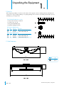
1.1 Parts List
Unpacking the Equipment
1.
Before beginning installation, check the overall condition of the equipment. Remove packing materials, and examine all
components for signs of shipping damage. Any shipping damage is the customer's responsibility and should be reported
immediately to your freight carrier.
1.2 Inlet Dimensions
A
Each BI28M/BI48M Inlet includes:
1 - Plastic Frame with 2 doors attached
1 - Insulation Stop, 12” tall
1 - Fiberglass Rod (BI48M only)
1 - Hardware Package as follows
4
3
⁄16”
31
7
⁄16"
52
7
⁄16"
27
9
⁄16”
6
1
⁄16”
HP1240 for BI28M Inlets
ID Qty. Cat. No. Description
[A] 8 KS1402 #9-15 x 1.5” Hex Head Screw
[B] 1 AC1381
1
⁄8” Dia. Cable Clamp, ZP
HP1248 for BI48M Inlets
[A] 12 KS1402 #9-15 x 1.5” Hex Head Screw
[B] 1 AC1381
1
⁄8” Dia. Cable Clamp, ZP
[C] 4 KX1003
1
⁄4” Dia. Retainer Clips, SS

5© Munters Corporation, May 2017
QM1110r5
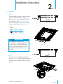
2.1 FRAMING
Step 1
Construct a framed opening in ceiling according
to Chart A and fasten to trusses or bracing
between trusses. Trim out framing with ‘J’-trim if
a metal ceiling is used. See Figure 1A and 1B.
If inlet is being installed in a house with a Tri-Ply
ceiling, construct frame as shown in Figure 1C.
Installation Instructions
2.
Figure 1A
Figure 1B
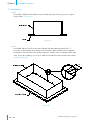
Step 2
The hardware should already be installed as
shown in Figure 2. The Lift Line should be turned
towards actuator and Eye Bolt will be away from
actuator.
25
1
⁄2" 25
1
⁄2”
25
1
⁄2” 46
1
⁄2”
Chart A
Figure 1C
Figure 2
If installing inlets near heaters, it is
recommended to install the BI28/BI48 inlet
at a location far enough from heaters that
will give a maximum temperature of 150°F.
This should be approximately 2-3 ft. from
the heater.
IMPORTANT
!

© Munters Corporation , May 2017
6
QM1110r5
Installation InstructionsChapter 2
Figure 3B
Step 3A
For the BI28, install provided Insulation Stop into framed opening as shown using screws or staples
(not provided). See Figure 3A.
2.2 Inlet Mounting
Figure 3A
Step 3B
For the BI48, find the center of the long side of framing and start installing Insulation Stop 1
1
⁄2”
from center, so that Insulation Stop overlaps center of opening. When Insulation Stop is completely
installed the 2 ends of Insulation Stop should overlap by 3” and the center of overlap should be at the
center of long side of framing. Use screws or staples (not provided) to fasten Insulation Stop in place.
See Figure 3A and 3B.

7© Munters Corporation, May 2017
QM1110r5
Installation InstructionsChapter 2
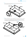
Step 3C
At the center of the long side of Insulation Stop,
1
⁄2” down from top, drill or punch a
1
⁄4” Dia.
hole on each side of Insulation Stop. See Figure 3C.
Figure 3C
Figure 3D
Step 3D
Install (1) Retaining Clip [C] on each end of Fiberglass Rod. The Retaining Clip should be 1
1
⁄2” from end
of rod. Insert one end of rod through the new hole in Insulation Stop from inside out. Insert other end
of rod through hole in opposite side of Insulation Stop. Secure Rod in place with a Retaining Clip [C] on
each end of Rod, so that Insulation Stop is between 2 of the clips. See Figure 3D.

© Munters Corporation , May 2017
8
QM1110r5
Installation InstructionsChapter 2
Figure 4A
Step 4
Apply bead of caulk around top of inlet as shown in Figure 4A. Position inlet into framed opening and
attach inlet using Hex Head Screws [A] provided, (8) for BI28, (12) for BI48. See Figure 4B. Be careful
not to over tighten as this may pull the Inlet Frame out of shape.
Step 5
To ensure an airtight fit, caulk around outside of 2x4 Framing and Inlet Frame.
Figure 4B
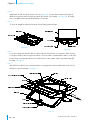
Step 6
Proceed to routing main actuator cable or rod through holes in Inlet Frame. It is required to utilize a spring
or weight on actuator cable end opposite actuator. Once the cable is routed and the actuator is in the open
position, begin connecting the Lift Lines from each inlet door to the actuator cable using Cable Clamp [B]
provided. See Figure 5.
Step 7
After Lift Lines for all inlets are connected and doors are adjusted as needed, caulk the hole in the door for
the Lift Line to prevent air leaks. See Figure 5.
Figure 5

9© Munters Corporation, May 2017
QM1110r5
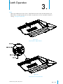
Latch Operation
3.
Step 8
Latch is pre-installed near center of door. Rotate latch upward to unlock and downward to lock.
When inlet is in normal operation, be sure latch is in up position so it does not interfere with door
closing. See Figure 6A and 6B.
Figure 6A
Latch Shown in Open Position
Figure 6B
Latch Shown in Closed Position

© Munters Corporation , May 2017
10
QM1110r5
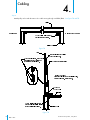
Cabling
4.
Step 9
Attach pulleys in line with the main rod or cable running through each BI28/BI48. See Figure 7A and 7B.
Figure 7A
Figure 7B

11© Munters Corporation, May 2017
QM1110r5
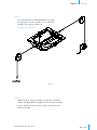
CablingChapter 4
Step 10
On each end of the run of BI28/BI48 inlets run a cable
through pulleys to winch or actuator on one end and to
weights or return spring on other end.
See Figure 7A, 7B and 8.
Figure 8
Step 11
With the winch or actuator at its fully closed position, check and
readjust each BI28/BI48 door tightly closed. Use winch or actuator
to open and close inlets a few times to make sure the doors open
and close smoothly

© Munters Corporation , May 2017
12
QM1110r5
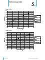
Performance Data
5.
BI28M, BI28M-01
BI48M, BI48M-01

13© Munters Corporation, May 2017
QM1110r5
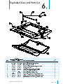
Exploded View and Parts List
6.

© Munters Corporation , May 2017
14
QM1110r5
Munters Europe AB, Isafjordsgatan 1, P.O. Box 1150, SE-164 26 Kista, Sweden. Phone +46 08 626 63 00, Fax +46 8 754 56 66.
Munters Corporation 2691 Ena Drive Lansing, MI 48917 U.S.A. Phone +1 800-227-2376, Fax +1 517-676-7078
www.munters.us
Australia Munters Pty Limited, Phone +61 2 6025 6422, Brazil Munters Brasil Industria e Comercio Ltda, Phone +55 41 3317 5050, Canada/US Munters
Corporation Lansing, MI Phone +1 517 676 7070, China Munters Air Treatment Equipment (Beijing) Co. Ltd, Phone +86 10 80 481 121, Denmark Munters A/S,
Phone +45 9862 3311,
India Munters India, Phone +91 20 3052 2520, Indonesia Munters, Phone +62 818 739 235, Italy Munters Italy S.p.A., Chiusavecchia,
Phone +39 0183 52 11, Japan Munters K.K., Phone +81 3 5970 0021, Korea Munters Korea Co. Ltd., Phone +82 2 761 8701, Mexico Munters Mexico, Phone
+52 818 262 54 00, Russia Munters AB, Phone +7 812 448 5740, Singapore Munters Pte Ltd., Phone +65 744 6828, South Africa and Sub-Sahara Countries
Munters (Pty) Ltd., Phone +27 11 997 2000, Spain Munters Spain S.A., Phone +34 91 640 09 02, Sweden Munters AB, Phone +46 8 626 63 00, Thailand
Munters Co. Ltd., Phone +66 2 642 2670, Turkey Munters Form Endüstri Sistemleri A.Ş, Phone +90 322 231 1338, USA Munters Corporation Lansing, MI Phone
+1 517 676 7070, Vietnam Munters Vietnam, Phone +84 8 3825 6838, Export & Other countries Munters Italy S.p.A., Chiusavecchia Phone +39 0183 52 11
BI28/BI48 Inlets are developed and produced by Munters Corporation, Lansing, Michigan U.S.A. 1-800-227-2376
-
 1
1
-
 2
2
-
 3
3
-
 4
4
-
 5
5
-
 6
6
-
 7
7
-
 8
8
-
 9
9
-
 10
10
-
 11
11
-
 12
12
-
 13
13
-
 14
14


Munters BI28M BI48M Manuale del proprietario
- Tipo
- Manuale del proprietario
in altre lingue
- English: Munters BI28M BI48M Owner's manual
Documenti correlati
-
Munters BI28SPM Manuale del proprietario
-
-
-
-
-
-
-
-
-