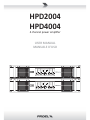
HPD2004
HPD4004
4 channel power amplifi er
USER MANUAL
MANUALE D'USO
PROTECT
BRIDGE
ON
LIMIT
SIGNAL
PROTECT
LIMIT
SIGNAL
PROTECT
BRIDGE
ON
LIMIT
SIGNAL
PROTECT
LIMIT
SIGNAL

FCC COMPLIANCE NOTICE
This device complies with part 15 of the FCC rules. Opera on is subject to the following two condi ons:
(1) This device may not cause harmful interference, and
(2) this device must accept any interference received, including interference that may cause undesired opera on.
CAUTION: Changes or modifi ca ons not expressly approved by the party responsible for compliance could void
the user’s authority to operate the equipment.
NOTE: This equipment has been tested and found to comply with the limits for a Class B digital device, pursuant to
part 15 of the FCC Rules. These limits are designed to provide reasonable protec on against harmful interference in
a residen al installa on. This equipment generates, uses, and can radiate radio frequency energy and, if not installed
and used in accordance with the instruc on manual, may cause harmful interference to radio communica ons.
However, there is no guarantee that interference will not occur in a par cular installa on. If this equipment does
cause harmful interference to radio or television recep on, which can be determined by turning the equipment off
and on, the user is encouraged to try to correct the interference by one or more of the following measures:
• Reorient or relocate the receiving antenna.
• Increase the separa on between the equipment and receiver.
• Connect the equipment into an outlet on a circuit diff erent from that to which the receiver is connected.
• Consult the dealer or an experienced radio/TV technician for help.
This marking shown on the product or its literature, indicates that it should not be disposed with other household wastes at the end of
its working life. To prevent possible harm to the environment or human health from uncontrolled waste disposal, please separate this
from other types of wastes and recycle it responsibly to promote the sustainable reuse of material resources. Household users should
contact either the retailer where they purchased this product, or their local government offi ce, for details of where and how they can
take this item for environmentally safe recycling. Business users should contact their supplier and check the terms and condi ons of the
purchase contract. This product should not be mixed with other commercial wastes for disposal.
The lightning fl ash with arrowhead symbol within an equilateral triangle is intended to alert the user to the presence of uninsulated
“dangerous voltage” within the product’s enclosure, that may be of suffi cient magnitude to cons tute a risk of electric shock to persons.
The exclama on point within an equilateral triangle is intended to alert the user to the presence of important opera ng and maintenance
(servicing) instruc ons in the literature accompanying the appliance.
The informa on contained in this publica on has been carefully prepared and checked. However no responsibility will be taken for any errors. All
rights are reserved and this document cannot be copied, photocopied or reproduced in part or completely without wri en consent being obtained
in advance from PROEL. PROEL reserves the right to make any aesthe c, func onal or design modifi ca on to any of its products without any prior
no ce. PROEL assumes no responsibility for the use or applica on of the products or circuits described herein.
Il marchio riportato sul prodo o o sulla documentazione indica che il prodo o non deve essere smal to con altri rifi u domes ci al
termine del ciclo di vita. Per evitare eventuali danni all’ambiente si invita l’utente a separare questo prodo o da altri pi di rifi u e di
riciclarlo in maniera responsabile per favorire il riu lizzo sostenibile delle risorse materiali. Gli uten domes ci sono invita a conta are
il rivenditore presso il quale è stato acquistato il prodo o o l’uffi cio locale preposto per tu e le informazioni rela ve alla raccolta
diff erenziata e al riciclaggio per questo po di prodo o. Gli uten
aziendali sono invita a conta are il proprio fornitore e verifi care i
termini e le condizioni del contra o di acquisto. Questo prodo o non deve essere smal to unitamente ad altri rifi u commerciali.
Il simbolo del lampo con freccia in un triangolo equilatero intende avver re l'u lizzatore per la presenza di "tensioni pericolose" non isolate
all'interno dell'involucro del prodo o, che possono avere una intensità suffi ciente a cos tuire rischio di scossa ele rica alle persone.
Il punto esclama vo in un triangolo equilatero intende avver re l'u lizzatore per la presenza di importan istruzioni per l'u lizzo e la
manutenzione nella documentazione che accompagna il prodo o.
Le informazioni contenute in questo documento sono state a entamente reda e e controllate. Tu avia non è assunta alcuna responsabilità per
eventuali inesa ezze. Tu i diri sono riserva e questo documento non può essere copiato, fotocopiato, riprodo o per intero o in parte senza
previo consenso scri o della PROEL. PROEL si riserva il diri o di apportare senza preavviso cambiamen e modifi che este che, funzionali o di
design a ciascun proprio prodo o. PROEL non assume alcuna responsabilità sull’uso o sul l’applicazione dei prodo o dei circui qui descri .

3
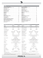
INDEX
TECHNICAL SPECIFICATIONS. . . . . . . . . . . . . . . . . . . . . . . . . . . .3
SETUP AND RACK MOUNTING (FIG. 1 / 2) . . . . . . . . . . . . . . . . .4
LOUDSPEAKER CABLE . . . . . . . . . . . . . . . . . . . . . . . . . . . . . . . . .4
CONNECTIONS . . . . . . . . . . . . . . . . . . . . . . . . . . . . . . . . . . . . . .5
FILTER RESPONSE (FIG.3) . . . . . . . . . . . . . . . . . . . . . . . . . . . . . .5
DIMENSIONS (FIG.4) . . . . . . . . . . . . . . . . . . . . . . . . . . . . . . . . . .6
FRONT PANEL (FIG.4) . . . . . . . . . . . . . . . . . . . . . . . . . . . . . . . . .6
REAR PANEL (FIG.5) . . . . . . . . . . . . . . . . . . . . . . . . . . . . . . . . . .7
EXAMPLE A . . . . . . . . . . . . . . . . . . . . . . . . . . . . . . . . . . . . . . . . .7
EXAMPLE B . . . . . . . . . . . . . . . . . . . . . . . . . . . . . . . . . . . . . . . . .8
EXAMPLE C . . . . . . . . . . . . . . . . . . . . . . . . . . . . . . . . . . . . . . . . .8
EXAMPLE D . . . . . . . . . . . . . . . . . . . . . . . . . . . . . . . . . . . . . . . . .9
EXAMPLE E . . . . . . . . . . . . . . . . . . . . . . . . . . . . . . . . . . . . . . . . .9
SAFETY AND PRECAUTIONS . . . . . . . . . . . . . . . . . . . . . . . . . . 10
IN CASE OF FAULT . . . . . . . . . . . . . . . . . . . . . . . . . . . . . . . . . . 10
TROUBLESHOOTING . . . . . . . . . . . . . . . . . . . . . . . . . . . . . . . . 10
CE CONFORMITY . . . . . . . . . . . . . . . . . . . . . . . . . . . . . . . . . . . 11
PACKAGING, SHIPPING AND COMPLAINT . . . . . . . . . . . . . . . 11
WARRANTY AND PRODUCTS RETURN . . . . . . . . . . . . . . . . . . 11
INSTALLATION AND DISCLAIMER . . . . . . . . . . . . . . . . . . . . . . 11
POWER SUPPLY AND MAINTENANCE . . . . . . . . . . . . . . . . . . 11
GENERAL INFORMATION . . . . . . . . . . . . . . . . . . . . . . . . . . . . 12
INSTRUCTIONS . . . . . . . . . . . . . . . . . . . . . . . . . . . . . . . . . . . . 12
INDICE
SPECIFICHE TECNICHE . . . . . . . . . . . . . . . . . . . . . . . . . . . . . . . .3
INSTALLAZIONE A RACK (FIG. 1 / 2) . . . . . . . . . . . . . . . . . . . . . .4
CAVO ALTOPARLANTE . . . . . . . . . . . . . . . . . . . . . . . . . . . . . . . . .4
CONNESSIONI . . . . . . . . . . . . . . . . . . . . . . . . . . . . . . . . . . . . . . .5
RISPOSTA FILTRI (FIG.3) . . . . . . . . . . . . . . . . . . . . . . . . . . . . . . .5
DIMENSIONI (FIG.4) . . . . . . . . . . . . . . . . . . . . . . . . . . . . . . . . . .6
PANNELLO FRONTALE (FIG.4) . . . . . . . . . . . . . . . . . . . . . . . . . . .6
PANNELLO POSTERIORE (FIG.5) . . . . . . . . . . . . . . . . . . . . . . . . .7
ESEMPIO A . . . . . . . . . . . . . . . . . . . . . . . . . . . . . . . . . . . . . . . . .7
ESEMPIO B . . . . . . . . . . . . . . . . . . . . . . . . . . . . . . . . . . . . . . . . .8
ESEMPIO C . . . . . . . . . . . . . . . . . . . . . . . . . . . . . . . . . . . . . . . . .8
ESEMPIO D . . . . . . . . . . . . . . . . . . . . . . . . . . . . . . . . . . . . . . . . .9
ESEMPIO E . . . . . . . . . . . . . . . . . . . . . . . . . . . . . . . . . . . . . . . . .9
AVVERTENZE PER LA SICUREZZA . . . . . . . . . . . . . . . . . . . . . . 15
IN CASO DI GUASTO . . . . . . . . . . . . . . . . . . . . . . . . . . . . . . . . 15
PROBLEMATICHE COMUNI . . . . . . . . . . . . . . . . . . . . . . . . . . . 15
CONFORMITÀ CE . . . . . . . . . . . . . . . . . . . . . . . . . . . . . . . . . . . 16
IMBALLAGGIO, TRASPORTO E RECLAMI . . . . . . . . . . . . . . . . 16
GARANZIE E RESI . . . . . . . . . . . . . . . . . . . . . . . . . . . . . . . . . . 16
INSTALLAZIONE E LIMITAZIONI D’USO . . . . . . . . . . . . . . . . . . 16
ALIMENTAZIONE E MANUTENZIONE . . . . . . . . . . . . . . . . . . . 16
INFORMAZIONI GENERALI . . . . . . . . . . . . . . . . . . . . . . . . . . . 17
ISTRUZIONI . . . . . . . . . . . . . . . . . . . . . . . . . . . . . . . . . . . . . . . 17
MODEL HPD2004 HPD4004 MODELLO HPD2004 HPD4004
Channels 4 (single) or 2 (bridge) Canali 4 (singoli) o 2 (ponte)
Power 8 ohm * 250 W 500 W Potenza Con nua 8ohm* 250 W 500 W
Power 4 ohm * 500 W 1000 W Potenza Con nua 4ohm* 500 W 1000 W
Power BRIDGE 8 ohm * 1000 W 2000 W Pot. Cont. BRIDGE 8ohm* 1000 W 2000 W
Frequency response 20 Hz - 20 kHz Risposta in Frequenza 20 Hz - 20 kHz
Input Sensi vity
(selectable)
Nominal: 0 dBu
Fixed: +3 dBu
Nominal: 0 dBu
Fixed: +5 dBu
Sensibilità Ingresso
(selezionabile)
Nominale: 0 dBu
Fissa: +3 dBu
Nominale: 0 dBu
Fissa: +5 dBu
Gain (nominal) 35 dB 38 dB Guadagno (nominale) 35 dB 38 dB
Gain (fi xed) 32 dB 32 dB Guadagno (fi sso) 32 dB 32 dB
Input Impedance 30 Kohm (bal) / 15 Kohm (unbal) Impedenza Ingresso 30 Kohm (bilanciato) / 15 Kohm (sbilanciato)
Input Connectors INPUT: COMBO (XLR-F/JACK)
LINK: XLR-M
Conne ori Ingresso INPUT: COMBO (XLR-F/JACK)
LINK: XLR-M
Output Connectors NL4 Speakon
(4x single, 2x bridge)
Conne ori Uscita NL4 Speakon
(4x singoli, 2x ponte)
Controls Level, HPF fi lter, BI-AMP crossover, Stereo /
Parallel / Bridge mode, GND li
Controlli Level, HPF fi lter, BI-AMP crossover, Stereo /
Parallel / Bridge mode, GND li
LED Indicators Signal, Limit, Protec on, Bridge, Power Indicatori LED Signal, Limit, Protec on, Bridge, Power
Cooling 2x Variable speed DC fan Raff reddamento 2 Ventole DC a velocità variabile
Protec ons Clip Limiter, Short circuit, DC voltage, Over
hea ng
Protezioni Clip Limiter, Short circuit, DC voltage, Over
hea ng
Damping Factor > 500 @ 8 ohm Fa ore Smorzamento > 500 @ 8 ohm
Slew Rate 50 V/uS Velocità di risposta 50 V/uS
S/N Ra o > 105 dB (unweighted) Rapporto S/R > 105 dB (unweighted)
THD+N < 0.5 % Distorsione + Rumore < 0.5 %
Power Supply 230 V~ or 120 V~ - 50/60 Hz Tensione alim. di rete 230 V~ or 120 V~ - 50/60 Hz
Max Consump on 2900 W 5300 W Consumo massimo 2900 W 5300 W
Rated Consump on** 800 W 1350 W Consumo nominale** 800 W 1350 W
Weight 11 Kg (24.3 lb) Peso 11 Kg (24.3 lb)
Dimensions (W x H x D) 483 x 89 x 383 mm (19 x 3.5 x 16.2 inch) Dimensioni (LxAxP) 483 x 89 x 383 mm (19 x 3.5 x 16.2 inch)
* Standard EIA 1KHz THD < 1%
** Rated consump on is measured with pink noise with a crest factor of 12
dB, this can be considered a standard music program.
* Standard EIA 1KHz THD < 1%
** Il consumo nominale è misurato con un rumore rosa con un fa ore di cresta
di 12 dB, considerato come un programma standard di musica.
TECHNICAL SPECIFICATIONS SPECIFICHE TECNICHE

4
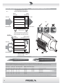
SETUP AND RACK MOUNTING (FIG. 1 / 2) INSTALLAZIONE A RACK (FIG. 1 / 2)
COLD AIR
FRONTALE
8U OPEN RACK
10U closed RACK
RACK aperto 8U
RACK chiuso 10U
POSTERIORE
FRONT REAR
FRONTALE POSTERIORE (chiuso)
FRONT REAR (closed)
ARIA FREDDA
COLD AIR
ARIA FREDDA
HOT AIR
HOT AIR
ARIA CALDA
ARIA CALDA
15 cm
6 inch
RECOMMENDED INSTALLATION
INSTALLAZIONE RACCOMANDATA
INSTALLATION WITH CLOSED BACK
INSTALLAZIONE CON RETRO CHIUSO
FIG.1
FIG.2
LOUDSPEAKER CABLE CAVO ALTOPARLANTE
ENGLISH: Loudspeaker Line Losses (maximum permissible line lengths for 0.5dB losses, voltage or spl)
ITALIANO: Perdite di collegamento linee Altoparlanti (massima lunghezza possibile per perdite inferiori a 0.5dB, tensione o spl)
4 ohm load 8 ohm load Wire sec on data PROEL recommended cables
feet meter feet meter mm² AWG 2 wires 4 wires 2 wires Fire-resistant
75 25 150 50 4.0 12 HPC624 HPC644 HPC624FRS
50 17.5 100 35 2.0 14 HPC620 HPC640 HPC620FRS
30 10 60 20 1.5 16 HPC610 HPC610FRS
20 7.5 40 15 1.0 18 HPC600
this is a short extrac on of the wide assortment of cables available from PROEL, please visit our website at www.proelgroup.com

5
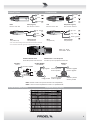
CONNECTIONS CONNESSIONI
sleeve - ground
INPUT (ingresso)
Jack (bilanciato)
INPUT
Jack (balanced)
p - hot
ring - cold
INPUT (ingresso)
XLR bilanciato maschio
INPUT
Balanced male XLR
ground
hot
cold
INPUT (ingresso)
Jack (sbilanciato)
INPUT
Jack (unbalanced)
ground
p - hot
cold
*nota: conneere insieme cold e ground per cavi da bilanciato a sbilanciato
*note: connect both cold and ground to make cable from balanced to unbalanced
LINK (rilancio ingresso)
XLR bilanciato femmina
LINK
Balanced female XLR
ground
hot
cold
PROEL code - NL4FX
Codice PROEL - NL4FX
POWER OUTPUT - uscite altoparlanƟ
Conneore per cavo po Speakon Neutrik NL4
SPEAKER POWER OUTPUTS
Neutrik NL4 Speakon Cable Connector
2-
1+
2+
1-
channel 1 posive
canale 1 posivo
1+
channel 1 negave
canale 1 negavo
1-
OUTPUT 1
2-
1+
2+
1-
bridge posive
n.c.
1+
bridge negave
1-
n.c.
OUTPUT BRIDGE
2-
1+
2+
1-
20mm
0.8"
8mm
0.3"
RED
BLACK
channel 2 posive
n.c.
1+
channel 2 negave
1-
n.c.
OUTPUT 2
uscita 1uscita BRIDGEuscita 2
channel 2 negave
canale 2 negavo
NOTE: channels 3 and 4 are equal to channel 1 and 2 respecvely.
NOTA: i canali 3 e 4 sono equivalen ai canali 1 e 2 rispevamente.
2-
channel 2 posive
canale 2 posivo
2+
FILTER RESPONSE (FIG.3) RISPOSTA FILTRI (FIG.3)
-0
+6
+12
+18
+24
+30
+36
dBu
20k
50 100 200
500 1k 2k 5k
10k
Hz
20
BI-AMP (CH1) BI-AMP (CH2)
HP (CH1-CH2)

6
PROTECT
BRIDGE
ON
LIMIT
SIGNAL
PROTECT
LIMIT
SIGNAL
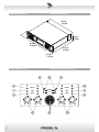
FRONT PANEL (FIG.4) PANNELLO FRONTALE (FIG.4)
DIMENSIONS (FIG.4)
DIMENSIONI (FIG.4)
48,3 cm
19.0 inch
43,4 cm
17,0 inch
36,7 cm
14.5 inch
8,9 cm
3.5 inch
4,2 cm
1.65 inch

7
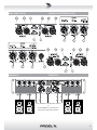
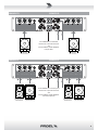
REAR PANEL (FIG.5) PANNELLO POSTERIORE (FIG.5)
EXAMPLE A ESEMPIO A
a2
a1
L
1+ 1-
4Ω minimum 4Ω minimum 4Ω minimum 4Ω minimum
set as STEREO for 4 indipendent channels
or
set as PARALLEL for 2 channel pairs
driven from a L/R audio channels
1+ 1- 1+ 1- 1+ 1-
R
a4 a3

8
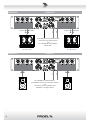
EXAMPLE B ESEMPIO B
EXAMPLE C ESEMPIO C
L
double subwoofer
4Ω + 4Ω minimum
set as PARALLEL for 2 double subwoofer
driven from a L/R audio channels
and
set as BI-AMP for 100Hz 24dB/oct.
low pass filter
1+ 2+
1- 2-
R
woofer 1 woofer 2
double subwoofer
4Ω + 4Ω minimum
1+ 2+
1- 2-
woofer 1 woofer 2
L
1+ 1-
8Ω minimum 8Ω minimum
set as BRIDGE for doubled power for
2 loudspeakers driven from a L/R audio channels
and
set as HPF if used in combinaon with
subwoofers or as stage monitors
1+ 1-
R

9
EXAMPLE D ESEMPIO D
EXAMPLE E ESEMPIO E
L
1+ 1-
subwoofer
8Ω minimum
subwoofer
8Ω minimum
set as BRIDGE for 2 subwoofer
driven from a L/R audio channels
and
set as BI-AMP for 100Hz 24dB/oct.
low pass filter
1+ 1-
R
L
1+ 1-
mid-high speaker
4Ω minimum
low subwoofer
4Ω minimum
mid-high speaker
4Ω minimum
low subwoofer
4Ω minimum
set as PARALLEL for 2 channel pairs
driven from a L/R audio channels
and
set as BI-AMP for 100Hz 24dB/oct.
crossover frequency
1+ 1- 1+ 1- 1+ 1-
R

10
SAFETY AND PRECAUTIONS
• CAUTION: before using this product read carefully the following safety instruc ons. Take a look of this manual en rely and preserve it for
future reference.
When using any electric product, basic precau ons should always be taken, including the following:
– To reduce the risk, close supervision is necessary when the product is used near children.
– Protect the apparatus from atmospheric agents and keep it away from water, rain and high humidity places.
– This product should be site away from heat sources such as radiators, lamps and any other device that generate heat.
– This product should be located so that its loca on or posi on does not interfere with its proper ven la on and hea ng dissipa on.
– Care should be taken so that objects and liquids do not go inside the product.
– The product should be connected to a power supply mains line only of the type described on the opera ng instruc ons or as marked on the
product. Connect the apparatus to a power supply using only power cord included making always sure it is in good condi ons.
–
WARNING: The mains plug is used as disconnect device, the disconnect device shall remain readily operable.
– Do not cancel the safety feature assured by means of a polarized line plug (one blade wider than the other) or with a earth connec on.
– Make sure that power supply mains line has a proper earth connec on.
– Power supply cord should be unplugged from the outlet during strong thunderstorm or when le unused for a long period of me.
– Do not place objects on the product’s power cord or place it in a posi on where anyone could trip over, walk on or roll anything over it. Do not
allow the product to rest on or to be installed over power cords of any type. Improper installa ons of this type create the possibility of fi re hazard
and/or personal injury.
– This product may be capable of producing sound levels that could cause
permanent hearing loss. Exposure to extremely high noise levels may cause
permanent hearing loss. Individuals vary considerably in suscep bility to noise-
induced hearing loss, but nearly everyone will lose some hearing if exposed
to sufficiently intense noise for a period of time. The U.S. Government’s
Occupational Safety and Health Administration (OSHA) has specified the
permissible noise level exposures shown in the following chart. According to
OSHA, any exposure in excess of these permissible limits could result in some
hearing loss. To ensure against poten ally dangerous exposure to high sound
pressure levels, it is recommended that all persons exposed to equipment
capable of producing high sound pressure levels use hearing protectors while
the equipment is in opera on. Ear plugs or protectors in the ear canals or over
the ears must be worn when opera ng the equipment in order to prevent
permanent hearing loss if exposure is in excess of the limits set forth here. Keep
your's a en on that children and pets are more suscep ble to excessive noise
levels.
IN CASE OF FAULT
• In case of fault or maintenance this product should be inspected only by qualifi ed service personnel when:
– There is a fl aw either in the connec ons or in the supplied connec ng cables.
– Liquids have spilled inside the product.
– The product has fallen and been damaged.
– The product does not appear to operate normally or exhibits a marked change in performance.
– The product has been lost liquids or gases or the enclosure is damaged.
• Do not operate on the product, it has no user-serviceable parts inside, refer servicing to an authorized maintenance centre.
TROUBLESHOOTING
No Power • The amplifi er's "POWER" switch is off .
• Make sure the mains AC outlet is live (check with a tester or a lamp).
• Make sure the mains plug is securely plugged into mains AC outlet.
No Sound • Is the input LEVEL control for the channel turned up?
• Is the SIGNAL LED illuminated? If not check if your signal level is too low or check the signal cable, mixer and other
equipment se ng and cabling.
• Are you sure your signal cables works properly? check it using a cable tester or replacing with a new one.
• Is the SPEAKON cable connector correctly inserted? turn it clockwise un l it clicks.
• Are you sure your power cable works properly? check it using a cable tester or replacing with a new one.
Distorted Sound • Input signal level is too high. Turn down your level controls.
NOTE: The loudspeakers should never be operated at a level which causes the amplifi er Clip LEDs to illuminate
constantly.
Diff erent channel
level
• Check if are using a balanced cable for one channel and an unbalanced one for the other, as this would cause a
considerable diff erence in channel levels.
• Be sure that your loudspeaker system is fully connected and both loudspeakers have the same impedance.
Noise / Hum • Enable GND LIFT bu on on rear panel, if the problem persist press all GND LIFT bu ons for all system's amplifi ers.
• Whenever possible, preferably use only balanced cables. Unbalanced lines may also be used but may result in noise
over long cable runs.
• Some mes it helps to plug all audio equipment into the same AC circuit so they share a common ground.
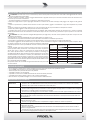
Dura on Per Day
In Hours
Sound Level dBA
Slow Response
Typical
Example
8 90 Duo in small club
692
4 95 Subway Train
397
2 100 Very loud classical music
1.5 102
1 105 Traffi c noise
0.5 110
0.25 or less 115 Loudest parts at a rock concert

11
No Sound and the
Amplifi er gets too hot
• The amplifi er temperature protec ons trips, re-locate the amplifi er in a more ven lated loca on.
No Sound and
Protec on trip
(LED PROTECT always
on)
• Could be a possible short circuit at the amplifi er loudspeakers outputs, the speaker’s inputs or in the cabling. Locate
and remove the short circuit.
• The impedance of the loudspeakers connected is too low. Use a speaker with a minimum impedance of 4Ω (8Ω in
the Bridge mode).
• If no load connected the protec on trips the same, a DC voltage has been detected in the amplifi er’s output circuit
and you have to contact you nearest service assistance center to repair the amplifi er.
CE CONFORMITY
• Proel products comply with direc ve 2004/108/EC (EMC), as stated in EN 55103-1 and EN 55103-2 standards and with direc ve 2006/95/CE
(LVD), as stated in EN 60065 standard.
• Under the EM disturbance, the ra o of signal-noise will be changed above 10dB.
PACKAGING, SHIPPING AND COMPLAINT
• This unit package has been submi ed to ISTA 1A integrity tests. We suggest you control the unit condi ons immediately a er unpacking it.
• If any damage is found, immediately advise the dealer. Keep all unit packaging parts to allow inspec on.
• Proel is not responsible for any damage that occurs during shipment.
• Products are sold “delivered ex warehouse” and shipment is at charge and risk of the buyer.
• Possible damages to unit should be immediately no fi ed to forwarder. Each complaint for package tampered with should be done within eight
days from product receipt.
WARRANTY AND PRODUCTS RETURN
• Proel products have opera ng warranty and comply their specifi ca ons, as stated by manufacturer.
• Proel warrants all materials, workmanship and proper opera on of this product for a period of two years from the original date of purchase. If
any defects are found in the materials or workmanship or if the product fails to func on properly during the applicable warranty period, the owner
should inform about these defects the dealer or the distributor, providing receipt or invoice of date of purchase and defect detailed descrip on.
This warranty does not extend to damage resul ng from improper installa on, misuse, neglect or abuse. Proel S.p.A. will verify damage on returned
units, and when the unit has been properly used and warranty is s ll valid, then the unit will be replaced or repaired. Proel S.p.A. is not responsible
for any "direct damage" or "indirect damage" caused by product defec veness.
INSTALLATION AND DISCLAIMER
• Proel products have been expressly designed for audio applica on, with signals in audio range (20Hz to 20kHz). Proel has no liability for damages
caused in case of lack of maintenance, modifi ca ons, improper use or improper installa on non-applying safety instruc ons.
• These amplifi ers are adapted in a properly ven lated, standard professional 19" rack. These units feature ven la on holes on the front and
back panels. Absolutely do not obstruct the ven la on holes. Blocked ven la on can cause damages and fi re.
• Do not locate sensi ve high-gain equipment such as mixer, preamplifi ers, recorders or AD/DA conversion units directly above or below these
amplifi ers. Because these amplifi ers have a high power density, it ha a strong magne c fi eld which can induce hum into unshielded devices that
are located nearby. If an equipment rack is used, we recommend loca ng the amplifi er in the bo om of the rack and the mixer, preamplifi er or
other sensi ve equipment at the top.
• Proel S.p.A. reserves the right to change these specifi ca ons at any me without no ce.
• Proel S.p.A. declines any liability for damages to objects or persons caused by lacks of maintenance, improper use, installa on not performed
with safety precau ons and at the state of the art.
POWER SUPPLY AND MAINTENANCE
• Clean only with dry cloth.
• Check periodically that the slots for its proper ven la on and hea ng dissipa on are not obstructed by dust, remove the dust using a dry brush
or a compressed air gun.
• The HPD2004 e HPD4004 amplifi ers of Proel have been designed with CLASS I construc on and must be connected always to a mains socket
outlet with a protec ve earth connec on (the third grounding prong).
• Before connec ng the product to the mains outlet make certain that the mains line voltage matches that shown on the rear of the product, a
tolerance of up to ±10% is acceptable.
• To disconnect these equipment from the AC Mains, disconnect the power supply cord plug from the AC receptacle.
•
THE REPLACEMENT OF FUSES INSIDE THE APPARATUS MUST BE MADE ONLY BY QUALIFIED PERSONNEL.
•
CHECK THE CONDITION OF THE PROTECTION FUSE, ACCESSIBLE OUTWARD, ONLY WITH THE APPARATUS SWITCHED OFF AND DISCONNECTED
FROM THE MAINS LINE OUTLET.
•
REPLACE THE PROTECTION FUSE ONLY WITH SAME TYPE AS SHOWN ON THE PRODUCT.
•
IF AFTER THE SUBSTITUTION, THE FUSE INTERRUPTS AGAIN THE APPARATUS WORKING, DO NOT TRY AGAIN THEN CONTACT THE PROEL
SERVICE CENTRE.

12
GENERAL INFORMATION
Thank you for having chosen a PROEL product.
HPD2004 and HPD4004 are 4-channel amplifi ers employing PROEL DA modules, a new genera on of digitally controlled
Class D power amplifi ers with Switch Mode Power Supply (SMPS) featuring an innova ve technology.
Unlike most of the class D amplifi ers, which use a fi xed switching frequency, the PWM (Pulse Width Modula on) output
stage of DA modules uses a variable switching frequency according to the input signal level.
Thanks to a sophis cated hardware and so ware structure, this system off ers performances far above most of the
products currently available on the market: be er sound defi ni on, high-fi delity reproduc on of any frequency of the
audio range, higher dynamics at any signal level with low distor on even at very high powers. The superior sound quality
can be compared with top-of-the-range AB-class analog systems, while DA modules thanks to the use of SMPS and Class
D feature very compact size and light weight, effi ciency above 90% and negligible heat dissipa on.
The very high effi ciency levels result also in a signifi cant reduc on in the energy waste associated with large installa ons,
a no ceable reduc on in opera ng costs and a direct benefi t to the environment. Featuring high power levels in
a lightweight and compact chassis, the HPD amplifi ers are much easier and more economical to transport than
conven onal models and this, in turn, makes them even more environmentally friendly.
HPD amplifi ers include an input sec on with the choice of diff erent fi ltering op ons (FLAT / BI-AMP / HPF) and feature
an ergonomic and func onal design with removable dust fi lters, for an easy maintenance in all condi ons of use
and therefore extensive durability. The protec on system includes thermal protec on, short circuit protec on, high
frequency protec on and CLIP LIMITER circuit.
INSTRUCTIONS
1. Power switch
Amplifi er is "ON" when the switch is in the "I" posi on.
2. Power indicator
Blue LED: when lighted indicates amplifi er has been turned on and AC power is available for each module 1-2 and 3-4.
3. Channel LEVEL Control
Rotary level control: in STEREO and PARALLEL opera on it a enuates the level of the signal sent to the correspondent
channel of the amplifi er, while in BRIDGE opera on the channel control 1 or 3 operates as single control for the channel
pair set as bridge (1-2 or 3-4 respec vely).
The a enua on ranges from “∞” fully closed (the signal is completely a enuated) to “0” fully open, nominal level (the
signal is not a enuated in any way, so is fed to the amplifi er channel at the same level at which it arrives on input).
4. Channel SIGNAL Indicator
Green LED illuminates to indicate the presence of the signal at the correspondent amplifi er channel.
5. Channel LIMIT Indicator
Red LED illuminates when the channel's output is limited. When this LED fl ashes reduce the input signal level.
6. Channel PROTECT Indicator
Yellow LED illuminates when the correspondent channel is in protect mode for one of the following reasons:
• The heatsink reaches a temperature above the normal working limit.
• There is a short circuit at the amplifi er output wires.
• The amplifi er output stages are faulty.
Consequently the channel is muted un l the reason of fault is removed.
7. BRIDGE mode indicator
Yellow LED illuminates when the channel pair 1-2 or 3-4 is in bridge mode.
NOTE: When the channel pair operates in BRIDGE mode SIGNAL, LIMIT and PROTECT LED indicators illuminate
simultaneously, the signal is sent to each pair from channel 1 or 3 input only and controlled by channel 1 or 3 level
control only.

13
8. INPUT
This is a female combo connector, which accepts a XLR or a JACK plug from almost any type of equipment with a
balanced or unbalanced outputs. The XLR input is wired as follows:
Pin 1 = shield or ground
Pin 2 = + posi ve or "hot"
Pin 3 = - nega ve or "cold"
The JACK input is wired as follows:
Tip = + posi ve or "hot"
Ring = - nega ve or "cold"
Sleeve = shield or ground
When connec ng an unbalanced signal, wire them as follows:
Pin2 / Tip = + posi ve or "hot"
Pin 1-3 / Sleeve = shield or ground
NOTE: whenever possible, use always balanced cables. Unbalanced lines may also be used but may result in noise over
long cable runs. In any case, avoid using a balanced cable for one channel and an unbalanced one for the other.
9. LINK
This is a male XLR connector, it is connected in parallel with the respec ve INPUT, so the LINK is wired at the same
way.
10. GND LIFT
This switch li the ground of the balanced audio inputs from the earth-ground of the amplifi er. If you have HUM noise
problem on one or more loudspeaker try to change the posi on of these switches.
11. GAIN
Allows the selec on of the amplifi er gain.
For HPD2004: when se ng a sensi vity of 0dBu (0.775Vrms) the gain is 35dB (56x), when se ng a gain of 32dB (40x)
the sensi vity is +3dBu (1.09Vrms).
For HPD4004: when se ng a sensi vity of 0dBu (0.775Vrms) the gain is 38dB (80x), when se ng a gain of 32dB (40x)
the sensi vity is +5dBu (1.38Vrms).
NOTE: The fi xed GAIN of 32dB is a useful feature to set a complex loudspeaker system using a loudspeaker processor:
in fact having a fi xed gain the calcula on of limiters is simplifi ed. See the manual of your loudspeaker processor for
details.
12. STEREO / BRIDGE / PARALLEL
Allows the selec on of STEREO, PARALLEL or BRIDGE mode opera ons.
• In STEREO mode each amplifi er channel pair runs independently driven by respec ve input (see EXAMPLE A).
• In BRIDGE mode the amplifi er channels pair runs together but with channel 1 or 3 in phase and channel 2 or 4 out
of phase. The channels pairs are driven by Channel 1 or 3 input and the output must be taken from "BRIDGE" speakon
output (see EXAMPLE C, D).
• In PARALLEL mode both amplifi er channels pair run together driven by Channel 1 or 3 input (see EXAMPLE A, B, E).
NOTE: use this se ng if your inten on are to use the BI-AMP feature also.
13. HPF / BI-AMP / FLAT
This useful switch allows the selec on of one of the following features:
• In HPF enables a 100Hz LR-24dB/Oct. High Pass Filter for both channels 1-2 or 3-4: this a useful feature for SAT-TOP
SPEAKERS or STAGE-MONITORS (see EXAMPLE C).
• In BI-AMP enables a Linkwitz-Riley crossover 24dB/Oct. at 100Hz between channel 1/3 and channel 2/4, then allows
a single amplifi er without a dedicated processor to drive a SUB-WOOFER with channel 1/3 and a SAT-TOP SPEAKER with
channel 2/4 (see EXAMPLE B, D, E).
• In FLAT no fi lters are inserted in the signal path (see EXAMPLE A).
14. Channel 1 or 3 SPEAKON output
Accepts a male Neutrik Speakon NL4FX connector wired in this way:
• PIN 1+ connected to POSITIVE output of Channel 1/3;
• PIN 1- connected to NEGATIVE output of Channel 1/3;
• PIN 2+ connected to POSITIVE output of Channel 2/4,
• PIN 2- connected to NEGATIVE output of Channel 2/4,

14
If you connect a standard 2 wire cable (1+/1-), you run to the speaker the amplifi ed output of the signal applied to
channel 1/3 input.
If you connect a standard 4 wire cable (1+/1-/2+/2-), you run to the speaker:
• with amplifi er set in STEREO mode, the amplifi ed outputs of the signal applied to channel 1/3 input (1+/1-) and to
channel 2/4 input (2+/2-),
• with amplifi er set in PARALLEL mode, the amplifi ed outputs of the signal applied to channel 1/3 input only, (1+/1-) =
(2+/2-),
In both modes using a single cable you can connect a BI-AMP loudspeaker or a SUB-SAT speaker system.
Always connect a loudspeaker with a minimum impedance of 4 ohm or more.
NOTE: Use only loudspeaker enclosure cables, never signal cables, i.e. those normally used for microphones, instruments
and audio equipment in general.
15. Channel 2 or 4 SPEAKON output
Accepts a male Neutrik Speakon NL4FX connector wired in this way:
• PIN 1+ connected to POSITIVE output of Channel 2/4;
• PIN 1- connected to NEGATIVE output of Channel 2/4;
• PIN 2+ and 2- NOT connected.
This is the amplifi ed output of the signal applied to channel 2/4 input if the amplifi er is set in STEREO mode or the signal
applied to channel 1/3 input if the amplifi er is set in PARALLEL mode.
Always connect a loudspeaker with a minimum impedance of 4 ohm or more.
16. BRIDGE SPEAKON output
Accepts a male Neutrik NL4FX connector wired in this way:
• PIN 1+ connected to "in phase" (Channel 1/3);
• PIN 1- connected to "out phase" (Channel 2/4);
• PIN 2+ and 2- NOT connected.
This is the amplifi ed output of the signal applied to channel 1/3 input if the amplifi er is set in BRIDGE mode.
Always connect a loudspeaker with a minimum impedance of 8 ohm or more.
NOTE: Use this output alone and only with BRIDGE mode se ng.
17. MAINS ~ cord
This is the amplifi er mains supply cord. Connect the power cord to an electrical outlet complying with the power supply
specifi ca ons indicated on the apparatus. Be sure your amplifi er is turned off before you plug the mains supply cord
into an electrical outlet.

15
AVVERTENZE PER LA SICUREZZA
• ATTENZIONE: Durante le fasi di uso o manutenzione, devono essere prese alcune precauzioni onde evitare danneggiamen alle stru ure
meccaniche ed ele roniche del prodo o.
Prima di u lizzare il prodo o, si prega di leggere a entamente le seguen istruzioni per la sicurezza. Prendere visione del manuale d’uso e
conservarlo per successive consultazioni:
– In presenza di bambini, controllare che il prodo o non rappresen un pericolo.
– Posizionare l’apparecchio al riparo dagli agen atmosferici e a distanza di sicurezza dall’acqua, dalla pioggia e dai luoghi ad alto grado di
umidità.
– Collocare o posizionare il prodo o lontano da fon di calore quali radiatori, griglie di riscaldamento e ogni altro disposi vo che produca
calore.
– Collocare o posizionare il prodo o in modo che non ci siano ostruzioni alla sua propria ven lazione e dissipazione di calore.
– Evitare che qualsiasi ogge o o sostanza liquida entri all’interno del prodo o.
– Il prodo o deve essere connesso esclusivamente alla rete ele rica delle cara eris che descri e nel manuale d’uso o scri e sul prodo o,
usando esclusivamente il cavo rete in dotazione e controllando sempre che sia in buono stato, in par colare la spina e il punto in cui il cavo esce
dal prodo o.
–
ATTENZIONE: Se il cavo rete viene scollegato dall'apparecchio per spegnerlo, il cavo rete rimarrà opera vo in quanto la sua spina è ancora
collegata alla rete ele rica.
– Non annullare la sicurezza garan ta dall'uso di spine polarizzate o con messa a terra.
– Fare a enzione che il punto di alimentazione della rete ele rica sia dotato di una effi ciente presa di terra.
– Disconne ere il prodo o dalla rete ele rica durante for temporali o se non viene usato per un lungo periodo di tempo.
– Non disporre ogge sul cavo di alimentazione, non disporre i cavi di alimentazione e segnale in modo che qualcuno possa incianparci. Altresì
non disporre l’apparecchio sui cavi di altri appara . Installazioni inappropriate
di questo po possono creare la possibilità di rischio di incendio e/o danni alle
persone.
– Questo prodo o può essere capace di produrre livelli sonori che possono
causare perdite d’udito permanen . Si raccomanda di evitare l’esposizione
ad alti livelli sonori o livelli non confortevoli per lunghi periodi di tempo.
Se si notano perdite d’udito o acufeni (fi schi) consultare un audiologo. La
sensibilità alla perdita di udito causata da eccessiva esposizione al rumore varia
considerevolmente da individuo a individuo, ma mediamente ciascuno può
accusare perdita di udito se esposto al rumore per un certo periodo di tempo.
Come suggerimento viene riportata la tabella dei tempi massimi di esposizione
giornaliera al rumore al fi ne di evitare perdite di udito, fonte della tabella è l'ente
per la salute degli Sta Uni (OSHA).
Si fa presente inoltre che sia i bambini che gli animali domes ci sono più sensibili
al rumore intenso.
IN CASO DI GUASTO
• In caso di guasto o manutenzione questo prodo o deve essere ispezionato da personale qualifi cato quando:
– Ci sono dife sulle connessioni o sui cavi di collegamento in dotazione.
– Sostanze liquide sono penetrate all’interno del prodo o.
– Il prodo o è caduto e si è danneggiato.
– Il prodo o non funziona normalmente esibendo una marcato cambio di prestazioni.
– Il prodo o perde sostanze liquide o gassose o ha l’involucro danneggiato.
• Non intervenire sul prodo o. Rivolgersi a un centro di assistenza autorizzato Proel.
PROBLEMATICHE COMUNI
Assenza di
alimentazione
• L'interru ore dell'altoparlante è spento.
• Accertarsi che ci sia eff e vamente tensione sulla presa di corrente (controllare con un tester o una lampada).
• Accertarsi che la spina di rete sia saldamente inserita nella presa.
Nessun Suono • È il controllo di livello LINE IN girato al massimo?
• È acceso il LED di segnale? Se no, controllate se il livello di segnale sia troppo basso o controllate il cavo di segnale,
le impostazioni e i cablaggi di mixer o altri apparecchi collega .
• Sei sicuro che il cavo di segnale sia in buono stato? controlla il cavo con un tester oppure sos tuiscilo con un'altro.
Suono Distorto • Il livello del segnale di ingresso è troppo alto, abbassare i controlli del livello.
NOTA: L'altoparlante non deve mai lavorare con livelli che fanno illuminare in modo pressoché costante il LED rosso
dell'amplifi catore.
Livello diff erente sui
canali
• Controllare se si stanno usando cavi bilancia su un canale e sbilancia sull'altro, ciò può comportare una notevole
diff erenza di livello sui canali.
• Assicurarsi che gli altoparlan siano completamente collega e abbiano la medesima impedenza.
Rumore / Ronzio • Abilitare l'interru ore GND LIFT sul pannello posteriore, se il problema persiste premere i GND LIFT su tu gli
amplifi catori del sistema.
• Qualora possibile, usare preferibilmente solo cavi bilancia . Cavi sbilancia possono essere usa ma risultano
rumorosi su lunghe distanze.
• Talvolta può essere di aiuto alimentare tu o l'equipaggiamento audio collegandolo dalla stessa linea di corrente
AC, in modo che tu gli appara condividano la stessa presa di terra.
Ore di esposizione
giornaliera
Livello sonoro in dBA
costante di tempo SLOW
Esempio
Tipico
8 90 Duo acus co in un piccolo club
692
4 95 Treno metropolitano
397
2 100 Musica classica molto forte
1.5 102
1 105 Rumore da traffi co urbano intenso
0.5 110
0.25 or less 115 Parte più rumorosa di un concerto rock

16
Nessun suono e
l'amplifi catore scalda
eccessivamente
• La protezione in temperatura sca a, riposizionate l'amplifi catore in un luogo più ven lato.
Nessun suono e
l'amplifi catore è in
protezione
(LED PROTECT
acceso)
• Potrebbe esserci un corto circuito alle uscite dell'amplifi catore, all'ingresso degli altoparlan o nel cavo di
collegamento. Localizzare e rimuovere il corto circuito.
• L'impedenza dell'altoparlante collegato è troppo bassa, usate un'altoparlante con una impedenza minima di 4Ω
(8Ω se in Bridge).
• Se senza altoparlan collega la protezione sca a ugualmente, una tensione con nua è presente in uscita,
conta are il più vicino centro assistenza PROEL.
CONFORMITÀ CE
• I Prodo Proel sono conformi alla dire va 2004/108/EC (EMC), secondo gli standard EN 55103-1 ed EN 55103-2 ed alla dire va 2006/95/CE
(LVD), secondo lo standard EN 60065.
• Se so oposto a disturbi EM, il rapporto segnale-rumore può essere superiore a 10dB.
IMBALLAGGIO, TRASPORTO E RECLAMI
• L’imballo è stato so oposto a test di integrità secondo la procedura ISTA 1A. Si raccomanda di controllare il prodo o subito dopo l’apertura
dell’imballo.
• Se vengono riscontra danni informare immediatamente il rivenditore. Conservare quindi l’imballo completo per perme erne l’ispezione.
• Proel declina ogni responsabilità per danni causa dal trasporto.
• Le merci sono vendute “franco nostra sede” e viaggiano sempre a rischio e pericolo del distributore.
• Eventuali avarie e danni dovranno essere contesta al ve ore. Ogni reclamo per imballi manomessi dovrà essere inoltrato entro 8 giorni dal
ricevimento.
GARANZIE E RESI
• I Prodo Proel sono provvis della garanzia di funzionamento e di conformità alle proprie specifi che, come dichiarate dal costru ore.
• La garanzia di funzionamento è di 24 mesi dopo la data di acquisto. I dife rileva entro il periodo di garanzia sui prodo vendu , a ribuibili a
materiali dife osi o dife di costruzione, devono essere tempes vamente segnala al proprio rivenditore o distributore, allegando evidenza scri a
della data di acquisto e descrizione del po di dife o riscontrato. Sono esclusi dalla garanzia dife causa da uso improprio o manomissione. Proel
SpA constata tramite verifi ca sui resi la dife osità dichiarata, correlata all’appropriato u lizzo, e l’eff e va validità della garanzia; provvede quindi
alla sos tuzione o riparazione dei prodo , declinando tu avia ogni obbligo di risarcimento per danni dire o indire eventualmente derivan
dalla dife osità.
INSTALLAZIONE E LIMITAZIONI D’USO
• I Prodo Proel sono des na esclusivamente ad un u lizzo specifi co di po sonoro: segnali di ingresso di po audio (20Hz-20kHz). Proel declina
ogni responsabilità per danni a terzi causa da mancata manutenzione, manomissioni, uso improprio o installazione non eseguita secondo le
norme di sicurezza.
• L'installazione di ques amplifi catori è prevista su rack 19" ven la per prodo ad uso professionale. Ques amplifi catori prevedono fori di
ven lazione sul frontale e sul retro del prodo o. Evitare assolutamente di ostruire la ven lazione fronte-retro dell'apparecchio onde prevenire
alte temperature al suo interno, che potrebbero provocare guas pericolosi e incendio.
• Non installare apparecchi con alta sensibilità e guadagno quali mixer, preamplifi catori, registratori, conver tori AD/DA dire amente sopra o
so o ques amplifi catori. Siccome ques amplifi catori hanno una notevole potenza generano un forte campo ele romagne co che può causare
disturbi in apparecchi privi di un adeguata schermatura nelle proprie vicinanze. Se un amplifi catore ed un apparecchio sensibile è installato nello
stesso rack si raccomanda di installare l'amplifi catore nella posizione più bassa e l'apparecchio sensibile nella posizione più alta.
• La Proel S.p.a. si riserva di modifi care il prodo o e le sue specifi che senza preavviso.
• Proel declina ogni responsabilità per danni a terzi causa da mancata manutenzione, manomissioni, uso improprio o installazione non eseguita
secondo le norme di sicurezza e a regola d'arte.
ALIMENTAZIONE E MANUTENZIONE
• Pulire il prodo o unicamente con un panno asciu o.
• Controllare periodicamente che le aperture di raff redamento non siano ostruite da accumuli di polvere, provvedere alla rimozione della polvere
mediante un pennello o aria compressa.
• Gli amplifi catori HPD2004 e HPD4004 della Proel sono costrui in CLASSE I e prevedono sempre il collegamento mediante presa di corrente con
terminale di terra di protezione (terzo terminale di terra).
• Prima di collegare l'apparecchio alla presa di corrente, accertatevi che la tensione di rete corrisponda a quella indicata sul retro dell’apparato,
è consen to un margine del ±10% rispe o al valore nominale.
• Per scollegare completamente ques apparecchi dalla rete estrarre la spina di alimentazione dalla presa di corrente.
•
LA SOSTITUZIONE DI FUSIBILI ALL'INTERNO DELL'APPARATO È CONSENTITO SOLAMENTE A PERSONALE QUALIFICATO.
• CONTROLLARE LO STATO DEI FUSIBILI DI PROTEZIONE ESCLUSIVAMENTE AD APPARATO SPENTO E DISCONNESSO DALLA RETE ELETTRICA.
•
RIMPIAZZARE IL FUSIBILE DI PROTEZIONE ESCLUSIVAMENTE CON UN FUSIBILE CON LE MEDESIME CARATTERISTICHE RIPORTATE SUL
PRODOTTO.
•
SE DOPO LA SOSTITUZIONE, IL FUSIBILE INTERROMPE NUOVAMENTE IL FUNZIONAMENTO DELL'APPARATO, NON INSISTERE E CONTATTARE
IL SERVIZIO ASSISTENZA PROEL.

17
INFORMAZIONI GENERALI
Grazie per aver scelto un prodo o PROEL.
HPD2004 e HPD4004 sono amplifi catori a 4 canali che u lizzano i moduli DA, una nuova generazione di amplifi catori di
potenza in Classe D a controllo digitale con alimentazione Switching (SMPS), dota di una tecnologia innova va.
A diff erenza di altri amplifi catori in classe D, i quali usano una frequenza di commutazione fi ssa, lo stadio di uscita PWM
(Pulse Width Modula on) dei moduli DA u lizza una frequenza di commutazione variabile a seconda del livello del
segnale. Grazie ad una sofi s cata stru ura hardware e so ware, questo sistema off re prestazioni ben al di sopra della
maggior parte dei prodo analoghi: migliore defi nizione del suono, riproduzione ad alta fedeltà di tu e le frequenze
della banda audio, dinamica superiore a qualunque livello di segnale con bassa distorsione anche a potenze molto
elevate. La qualità audio superiore può essere paragonata a quella di sistemi top di gamma in classe AB, mentre i
moduli DA, grazie all’uso di SMPS e Classe D, off rono dimensioni e pesi molto rido , un’effi cienza superiore al 90% e
dissipazione di calore trascurabile.
Gli eleva livelli di effi cienza hanno come risultato una notevole riduzione degli sprechi di energia associa all’u lizzo
di grandi impian di amplifi cazione, con un benefi cio dire o per l’ambiente ed un sensibile risparmio sui cos di
esercizio. In più, grazie alla possibilità di concentrare eleva livelli di potenza in dimensioni e pesi estremamente
contenu , il trasporto degli amplifi catori risulta molto più economico e a minor impa o ambientale rispe o a modelli
convenzionali.
La sezione d’ingresso di entrambi i modelli off re la scelta fra diverse opzioni di fi ltraggio (FLAT/BI-AMP/ HPF), mentre il
design ergonomico e funzionale, che include fi ltri an -polvere rimovibili, assicura una facile manutenzione in qualsiasi
condizione d’uso e una lunga durata nel tempo. Il sistema di protezioni include protezione termica, protezione sul corto
circuito, protezione in alta frequenza e circuito di CLIP LIMITER.
ISTRUZIONI
1. Interru ore accensione
L'amplifi catore è acceso "ON" quando l'interru ore è nella posizione "I".
2. Indicatore di accensione
LED blu: quando acceso indica che l'amplifi catore è stato acceso e l'alimentazione AC è disponibile per il modulo
corrispondente 1-2 e 3-4.
3. Controllo di Livello del Canale
Controllo di livello rota vo: in modalità STEREO e PARALLEL a enua il livello del segnale inviato al canale corrispondente
dell'amplifi catore, mentre in modalità BRIDGE il controllo di livello 1 o 3 agisce singolarmente per la coppia di canali
impostata in bridge (1-2 o 3-4 rispe vamente).
L' a enuazione varia tra completamente chiuso “∞” a completamente aperto “0” o livello nominale (il segnale non è
a enuato in nessun modo, viene inviato al canale dell'amplifi catore allo stesso livello con cui arriva all'ingresso).
4. Indicatore di segnale (SIGNAL) del Canale
LED verde che si accende per indicare la presenza del segnale sul canale corrispondente.
5. Indicatore di limitazione (LIMIT) del Canale
LED rosso che si accende quando l'uscita del canale è limitata. Quando questo LED lampeggia ridurre il segnale di
ingresso del canale corrispondente.
6. Indicatore di protezione (PROTECT) del Canale
LED giallo che si accende quando il canale corrispondente è in modalità prote a per uno dei seguen mo vi:
• Il dissipatore ha superato la temperatura limite di lavoro.
• È presente un corto circuito sui cavi di uscita.
• Lo stadio di uscita si è guastato.
Conseguentemente il canale resta chiuso fi nché il mo vo del guasto non sarà rimosso.
7. Indicatore di modalità BRIDGE
LED giallo che si accende quando la coppia di canali 1-2 o 3-4 è in modalità bridge.
NOTA: Quando la coppia di canali è in modalità BRIDGE i LED SIGNAL, LIMIT e PROTECT si accendono simultaneamente,
il segnale e inviato ad ogni coppia solo dall'ingresso del canale 1 o 3 e regolato solo dal controllo di livello del canale 1
o 3.

18
8. INPUT
Questo è un conne ore combinato XLR/JACK femmina che preleva il segnale da pra camente qualsiasi apparecchio
bilanciato o sbilanciato. Le terminazioni dell' ingresso XLR sono:
Pin 1 = schermo o massa
Pin 2 = + posi vo o "caldo"
Pin 3 = - nega vo o "freddo"
Le terminazioni dell' ingresso JACK sono:
Tip (punta) = + posi vo o "caldo"
Ring (anello) = - nega vo o "freddo"
Sleeve (manico o) = schermo o massa
E quando si collega un segnale sbilanciato, sono le seguen :
Pin2 / Tip (punta) = + posi vo o "caldo"
Pin 1-3 / Sleeve (manico o) = schermo o massa
NOTA: Se possibile, usare sempre cavi bilancia . Cavi sbilancia possono essere usa ma potrebbero dare problemi di
rumore se molto lunghi. In ogni caso, evitate di usare un cavo bilanciato per un canale e uno sbilanciato per l’altro.
9. LINK
Questo è un conne ore XLR maschio connesso in parallelo con il rispe vo conne ore INPUT, perciò il LINK è terminato
allo stesso modo.
10. GND LIFT
Questo interru ore solleva la massa degli ingressi audio bilancia dalla massa-terra dell'amplifi catore. Se si hanno
problemi di ronzio su uno o più altoparlan provare a cambiare la posizione di ques interru ori: perché abbiano eff e o
spesso occorre siano tu su o tu giù per tu gli amplifi catori e che tu i cavi siano bilancia .
11. GAIN
Perme e la selezione del guadagno dell'amplifi catore:
Per HPD2004: impostando una sensibilità di 0dBu (0.775Vrms) il guadagno è 35dB (56x), impostando un guadagno di
32dB (40x) la sua sensibilità è +3dBu (1.09Vrms).
Per HPD4004: impostando una sensibilità di 0dBu (0.775Vrms) il guadagno è 38dB (80x), impostando un guadagno di
32dB (40x) la sua sensibilità è +5dBu (1.38Vrms).
NOTA: Il guadagno fi sso a 32dB è una cara eris ca u le per l'impostazione di sistemi complessi di altoparlan con
processore: in quanto con un gain fi sso il calcolo dei limiter è semplifi cato. Consultare il manuale del processore per
altri de agli.
12. STEREO - PARALLEL - BRIDGE
Perme e la selezione delle modalità di funzionamento in STEREO, PARALLEL o BRIDGE.
• In modalità STEREO ogni coppia di canali dell'amplifi catore è indipendente e pilotata dal rispe vo ingresso (vedi
ESEMPIO A).
• In modalità BRIDGE la coppia di canali dell'amplifi catore funziona assieme ma con il canale 1 o 3 in fase e il canale 2 o
4 fuori fase, la coppia di canali dell'amplifi catore è pilotata dall'ingresso del canale 1 o 3 e l'uscita deve essere prelevata
dall'uscita speakon "BRIDGE" (vedi ESEMPIO C, D).
• In modalità PARALLEL la coppia di canali dell'amplifi catore è pilotata insieme dall'ingresso del canale 1 o 3 (vedi
ESEMPIO A, B, E).
NOTA: usare questa impostazione se si vuole usare anche l'impostazione BI-AMP.
13. HPF / BI-AMP / FLAT
Questo sele ore perme e la selezione di una delle seguen funzioni:
• In HPF abilita un fi ltro passa alto a 100Hz LR-24dB/Oct. per entrambe i canali 1-2 o 3-4: u le per fi ltrare altoparlan
SAT-TOP o MONITOR DI PALCO (vedi ESEMPIO C).
• In BI-AMP abilita un crossover Linkwitz-Riley 24dB/Oct. a 100Hz fra il canale 1/3 e il canale 2/4: ciò perme e ad un
singolo amplifi catore senza un processore dedicato di pilotare un SUB-WOOFER con il canale 1/3 e un SAT-TOP SPEAKER
con il canale 2/4 (vedi ESEMPIO B, D, E).
• In FLAT nessun fi ltro è inserito nel percorso del segnale (vedi ESEMPIO A).
14. Uscita SPEAKON Canale 1 o 3
Conne ore Neutrik Speakon NL4FX maschio, collegato come segue:
• PIN 1+ collegato all'uscita POSITIVA del canale 1/3;

19
• PIN 1- collegato all'uscita NEGATIVA del canale 1/3;
• PIN 2+ collegato all'uscita POSITIVA del canale 2/4;
• PIN 2- collegato all'uscita NEGATIVA del canale 2/4;
Se si collega un cavo standard a due fi li (1+/1-), si invia all'altoparlante il segnale amplifi cato del canale 1/3.
Se si collega un cavo standard a 4 fi li (1+/1-/2+/2-), si invia all'altoparlante:
• con l'amplifi catore in modalità STEREO, le uscite amplifi cate del segnale applicato all'ingresso del canale 1/3 (1+/1-)
e del canale 2/4 (2+/2-),
• con l'amplifi catore in modalità PARALLEL,le uscite amplifi cate del segnale applicato al solo ingresso del canale 1/3
(1+/1-) = (2+/2-),
In ognuno di ques modi usando un cavo singolo a 4 poli si può collegare un'altoparlante impostato in BI-AMP o un
sistema SUB-SAT.
Collegare sempre un altoparlante con un'impedenza minima di 4 ohm o superiore.
NOTA: Usare cavi specifi ci per altoparlan , mai cavi di segnale, quelli usa per microfoni, strumen e apparecchiature
audio in generale.
15. Uscita SPEAKON Channel 2 o 4
Conne ore Neutrik Speakon NL4FX maschio, collegato come segue:
• PIN 1+ collegato all'uscita POSITIVA del canale 2/4;
• PIN 1- collegato all'uscita NEGATIVA del canale 2/4;
• PIN 2+ PIN 2- non collega ;
Questa è l'uscita amplifi cata del segnale applicato all'ingresso del canale 2/4, se in modalità STEREO, o del segnale
applicato all'ingresso del canale 1/3, se in modalità PARALLEL.
Collegare sempre un altoparlante con un'impedenza minima di 4 ohm o superiore.
16. Uscita SPEAKON BRIDGE
Conne ore Neutrik Speakon NL4FX maschio, collegato come segue:
• PIN 1+ collegato all'uscita "in phase" (canale 1/3)
• PIN 1- collegato all'uscita "out phase" (canale 2/4);
• PIN 2+ e 2- NON connessi.
Questa è l'uscita amplifi cata del segnale applicato all'ingresso del canale 1/3 se l'amplifi catore è impostato in modalità
BRIDGE.
Collegare sempre un altoparlante con un'impedenza minima di 8 ohm o superiore.
NOTA: Usare questa uscita da sola ed unicamente in modo BRIDGE.
17. Cavo di ALIMENTAZIONE dalla rete ele rica ~
Questo è il cavo di alimentazione di rete. Collegare l'altro capo del cavo di alimentazione ad una presa di rete ele rica
conforme con le specifi che di alimentazione riportate sull'apparato. Assicurarsi che l'amplifi catore sia spento prima di
inserire la spina del cavo nella presa di rete.

REV. 45/13 CODE 96MAN0083
PROEL S.p.A.
(World Headquarter)
Via alla Ruenia 37/43
64027 Sant’Omero (TE) - ITALY
Tel: +39 0861 81241
Fax: +39 0861 887862
www.proel.com
-
 1
1
-
 2
2
-
 3
3
-
 4
4
-
 5
5
-
 6
6
-
 7
7
-
 8
8
-
 9
9
-
 10
10
-
 11
11
-
 12
12
-
 13
13
-
 14
14
-
 15
15
-
 16
16
-
 17
17
-
 18
18
-
 19
19
-
 20
20


PROEL HPD4004 Manuale utente
- Tipo
- Manuale utente
- Questo manuale è adatto anche per
in altre lingue
- English: PROEL HPD4004 User manual