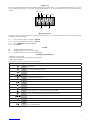
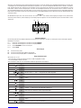
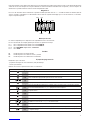
MATRIX / MATRIX-RE / CP.BULL / CP.BULL-RI
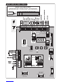
J1 DAS
Open
DAS N.C.
J1 DAS
Close
DAS 8K2
45
67
RX
2 CH.
SHIELD
ANT
LN
Service
Light
230V
SCA 24Vac
3W max
SERL:On
SERL:Off
230V: F5A
115V: F10A
230V: T0,315
115V: T0,5
230V: T1A
115V: T1A
Relè 24Vac
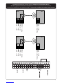
A
B
C
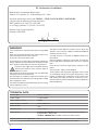
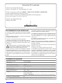
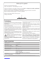
ENCODER
MATRIX
ENCODER
CP.BULL
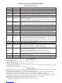
MATRIX > BULL10M SC/15M SC
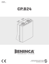
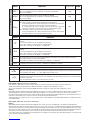
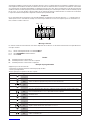
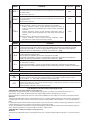
Collegamento Encoder - Encoder Connection - Anschluss Encoder
Branchement Encodeur - Conexión Encoder - Połączenia Enkoderem
3x0,5mm2
max 10m
A Signal Bianco/White/Weiss/Blanc/Blanco/Biały
B +5V Marrone/Brown/Braun/Marron/Marrón/Brązowy
C GND Verde/Green/Grüne/Verte/Verde/Zielony

3
24Vac 24Vac
COM
NC
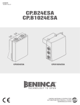
RX1 TX1
24Vac 24Vac
COM
NC
RX2 TX2
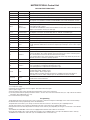
Phtoto TEST - 13
24Vac - 8
24Vac - 8
24Vac - 9
COM - 19
PHOT C - 24
Phtoto TEST - 13
24Vac - 8
24Vac - 8
24Vac - 9
COM - 19
PHOT O - 21
Collegamento dispositivi di sicurezza verificati / Connection of tested safety devices
Anschluss geprüfter Sicherheitsvorrichtungen / Branchement dispositifs de sécurité vérifiés
Conexión de los dispositivos de seguridad verificados / Połączenia sprawdzanych urządzeń bezpieczeństwa

4
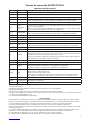
Dichiarazione CE di conformità
Fabbricante: Automatismi Benincà SpA.
Indirizzo: Via Capitello, 45 - 36066 Sandrigo (VI) - Italia
Dichiara che: la centrale di comando CP.BULL / CP.BULL-RI / MATRIX / MATRIX-RE.
è conforme alle seguenti disposizioni pertinenti:
Direttiva sulla compatibilità elettromagnetica: 89/336/CCE, 93/68/CEE
Direttiva sulla bassa tensione: 73/23/CEE, 93/68/CEE
Benincà Luigi, Responsabile legale.
Sandrigo, 08/08/2008.
AVVERTENZE
Questo manuale è destinato esclusivamente a personale
qualificato per l’installazione e la manutenzione di aperture
automatiche.
Nessuna informazione qui presente è di interesse o di utilità
per l’utente finale.
Conservare questo manuale per futuri utilizzi.
L’installatore deve fornire tutte le informazioni relative al
funzionamento automatico, manuale e di emergenza dell'au-
tomazione, e consegnare all’utilizzatore dell’impianto le
istruzioni d’uso.
•Prevedere sulla rete di alimentazione un inter-
ruttore/sezionatore onnipolare con distanza
d’apertura dei contatti uguale o superiore a 3 mm.
Verificare che a monte dell’impianto elettrico vi sia un interrut-
tore differenziale e una protezione di sovracorrente adeguati.
Alcune tipologie di installazione richiedono il collegamento
dell'anta ad un impianto di messa a terra rispondente alle
vigenti norme di sicurezza.
L’installazione elettrica e la logica di funzionamento devono
essere in accordo con le normative vigenti.
I conduttori alimentati con tensioni diverse, devono essere
fisicamente separati, oppure devono essere adeguatamente
isolati con isolamento supplementare di almeno 1 mm.
I conduttori devono essere vincolati da un fissaggio supple-
mentare in prossimità dei morsetti.
Durante gli interventi di installazione, manutenzione e ripa-
razione, togliere l’alimentazione prima di accedere alle parti
elettriche.
Ricontrollare tutti i collegamenti fatti prima di dare tensione.
Gli ingressi N.C. non utilizzati devono essere ponticellati.
Le descrizioni e le illustrazioni presenti in questo manuale
non sono impegnative. Lasciando inalterate le caratteristi-
che essenziali del prodotto il fabbricante si riserva il diritto di
apportare qualsiasi modifica di carattere tecnico, costruttivo
o commerciale senza impegnarsi ad aggiornare la presente
pubblicazione.
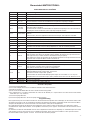
DATI TECNICI
Alimentazione di rete 230 Vac 50/60 Hz
Uscita Motore 1 motore 230Vac
Potenza massima motore 1000 W
Uscita alimentazione accessori 24Vdc 500mA max.
Grado di protezione IP54
Temp. funzionamento -20°C / +70°C
Ricevitore radio
CP.BULL-RI / MATRIX: 433,92 MHz incorporato e configurabile (rolling-code
o fisso+rolling-code)
CP.BULL / MATRIX-RE: Connettore ad innesto per ricevente radio.
N° codici memorizzabili 64
Dispone di funzione di verifica “Test singolo guasto” ai sensi della Direttiva Macchine 98/37/CE.

5
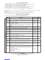
Centrale di comando MATRIX/CP.BULL
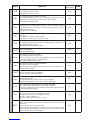
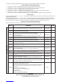
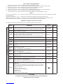
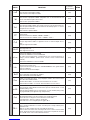
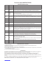
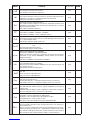
FUNZIONI INGRESSI/USCITE
N° Morsetti Funzione Descrizione
1-2 Alimentazione Ingresso 230Vac 50Hz (1-Fase/2-Neutro)
3 GND Collegamento messa a terra (obbligatorio)
4-5 Antenna Collegamento antenna scheda radioricevente ad innesto (4-segnale/5-schermo).
6-7 RX 2° Ch Uscita secondo canale radio. Contatto N.O. libero da tensione.
Non disponibile nelle centrali CP.BULL-RI e MATRIX con ricevitore incorporato.
8-9 24Vac Uscita alimentazione accessori 24Vac/500mA max
10-11 SCA o
Luce di servizio
Contatto pulito N.O. Configurabile come SCA (spia cancello aperto) o Luce di servizio tem-
porizzata (vedi Logica SERL).
Nelle centrali CP.BULL-RI e MATRIX con ricevitore incorporato può essere configurata
come uscita secondo canale radio (vedi Logica 2Ch).
12-13 PHOTO TEST
Contatto pulito N.O. Utilizzato per alimentare i trasmettitori delle fotocellule in modalità
TEST.
Vedi schema “Collegamento dispositivi di sicurezza verificati” e Logiche TST1 e TST2.
14 COM Comune per gli ingressi di comando.
15 OPEN Ingresso pulsante APRE (contatto N.O.).
16 CLOSE Ingresso pulsante CHIUDE (contatto N.O.)
17 Passo-Passo Ingresso pulsante passo-passo (contatto N.O.)
18 PED Ingresso pulsante pedonale (contatto N.O.), comanda l’apertura parziale, configurabile dal
parametro TPED. Al termine del tempo TCA (se attivato) viene comandata la chiusura.
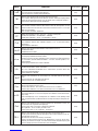
19 COM Comune per finecorsa e sicurezze
20 STOP Ingresso pulsante STOP (contatto N.C.)
21 PHOT O
Ingresso (contatto N.C.) per dispositivi di sicurezza (ad es. fotocellule).
In fase di chiusura: l’apertura del contatto provoca l’arresto del motore, quando la fotocel-
lula viene liberata, il motore inverte la direzione di marcia (apre).
In fase di apertura: l’apertura del contatto provoca l’arresto del motore, quando la fotocel-
lula viene liberata, il motore riparte in apertura.
22 SWO Ingresso finecorsa APRE (contatto N.C.)
23 SWC Ingresso finecorsa CHIUDE (contatto N.C.)
24 PHOT C
Ingresso (contatto N.C.) per dispositivi di sicurezza (ad es . fotocellule).
In fase di chiusura: Comportamento configurabile dalla logica PHTC.
In fase di apertura: Comportamento configurabile dalla logica PHTC.
25-26 DAS
Ingresso contatto costa sensibile
Costa resistiva: Jumper “DAS” chiuso
Costa meccanica: Jumper “DAS” aperto
L’intervento della costa arresta il movimento dell’anta e inverte per circa 3s.
Se non si utilizza la costa: Jumper “DAS” aperto, ponticello tra i morsetti 25-26.
27-28-29 Motore Collegamento motore 230Vac - monofase:
27-Fase/28-Comune/29-Fase
27-30 Condensatore Collegamento condensatore
31-32 Lampeggiante Collegamento lampeggiante 230Vac 40W max.
Verifica collegamenti:
1) Togliere alimentazione.
2) Sbloccare manualmente l’anta, portarle a circa metà della corsa e ribloccarla.
3) Ripristinare l’alimentazione.
4) Dare un comando di passo-passo mediante pulsante o radiocomando.
5) L’anta deve muoversi in apertura. Nel caso ciò non avvenisse, invertire tra loro i fili di marcia (27< >29) del motore e i fili del
finecorsa SWO-SWC (22< >23).
6) Togliere alimentazione/Ripristinare l’alimentazione.
Programmazione
La programmazione delle varie funzionalità della centrale viene effettuata utilizzando il display LCD presente a bordo della centrale
ed impostando i valori desiderati nei menu di programmazione descritti di seguito.
Il menu parametri consente di impostare un valore numerico ad una funzione, in modo analogo ad un trimmer di regolazione.
Il menu logiche consente di attivare o disattivare una funzione, in modo analogo al settaggio di un dip-switch.
Altre funzioni speciali seguono i menu parametri e logiche e possono variare a seconda del tipo di centrale o revisione software.
Le centrali CP.BULL-RI e MATRIX sono dotate di un modulo radio incorporato per la ricezione di telecomandi sia a codice fisso che
a codice variabile con frequenza di 433.92MHz e in grado di memorizzare fino a 64 codici diversi.
Il menu RADIO e le logiche 2Ch e CVAR sono disponibili solo in queste centrali.
Le centrali CP.BULL e MATRIX-RE sono dotate di connettore per ricevitore ad innesto.

6
Per accedere alla programmazione:
1 Premere il pulsante <PG>, il display si porta nel primo menu Parametri “PAR”.
2 Scegliere con il pulsante <+> o <-> il menu che si intende selezionare (PAR>>LOG>>RADIO>>NMAN>>RES).
3 Premere il pulsante <PG>, il display mostra la prima funzione disponibile nel menu.
4 Scegliere con il pulsante <+> o <-> la funzione che si intende modificare.
5 Premere il pulsante <PG>, il display mostra il valore attualmente impostato per la funzione selezionata.
6 Selezionare con il pulsante <+> o <-> il valore che si intende assegnare alla funzione.
7 Premere il pulsante <PG>, il display mostra il segnale “PRG” che indica l’avvenuta programmazione.
Note:
La pressione simultanea di <+> e <-> effettuata all’interno di un menu funzione consente di tornare al menu superiore senza appor-
tare modifiche.
La pressione simultanea di <+> e <-> effettuata a display spento visualizza la versione software della scheda.
Mantenere la pressione sul tasto <+> o sul tasto <-> per accelerare l’incremento/decremento dei valori.
Dopo un’attesa di 30s la centrale esce dalla modalità programmazione e spegne il display.
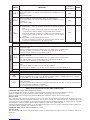
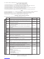
Parametri, Logiche e Funzioni Speciali
Nelle tabelle di seguito vengono descritte le singole funzioni disponibili nella centrale.
MENU FUNZIONE Valori impostabili
MIN-MAX-(Default) MEMO
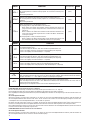
PARAMETRI
TCA Tempo di chiusura automatica. Attivo solo con logica “TCA”=ON.
Al termine del tempo impostato la centrale comanda una manovra di chiusura. 1-240-(40s)
Tped Regola lo spazio percorso dall’anta durante l’apertura parziale (pedonale).
Valore espresso in decimetri. 2-100-(5dm)
Tsm
Regola lo spazio percorso dall’anta durante la fase di rallentamento.
0 = rallentamento disabilitato.
Il comportamento dell’automazione durante le prime manovre dipende dalla
logica ENC. Vedi paragrafo “Modalità di funzionamento con Encoder abilitato/
disabilitato”
0-100-(0%)
PMo Regola la coppia applicata al motore durante la fase di apertura.* 1-99-(50%)
PMC Regola la coppia applicata al motore durante la fase di chiusura.* 1-99-(50%)
Pso Regola la coppia applicata al motore durante la fase di rallentamento in aper-
tura* 1-99-(50%)
Psc Regola la coppia applicata al motore durante la fase di rallentamento in chiu-
sura* 1-99-(50%)
SeaU
Regola la soglia di intervento del dispositivo antischiacciamento (Encoder)
durante la fase a velocità normale*.
0:Off -1:massima sensibilità - 99: minima sensibilità
0-99-(0%)
SEAR
Regola la soglia di intervento del dispositivo antischiacciamento (Encoder)
durante la fase di rallentamento*.
0:Off -1:massima sensibilità - 99: minima sensibilità
0-99-(0%)
TLS Attivo solo con logica SERL:ON. Regola il tempo di attivazione della luce di
servizio. 1-240-(60s)
Ibra Regola la forza del freno motore.
0: frenatura disabilitata - 1:frenatura minima - 99: frenatura massima 0-99-(50%)
TM
Attivo solo con logica ENC:OFF.
Tempo lavoro motore. Regola il tempo di funzionamento a velocità normale
durante la fase di apertura e chiusura del motore.
1-250-(150s)
BLC
Ritardo stop motore su finecorsa. Attivo solo con rallentamento (TSM) abilitato.
Regola il tempo di ritardo di arresto del motore a seguito di intervento del fine-
corsa. Utilizzare un valore proporzionato al peso del cancello, utilizzare questi
valori indicativi:
0 disattivo (nessun ritardo)
1 cancelli molto pesanti (ritardo breve)
2 cancelli pesanti
3 cancelli medi
4 cancelli leggeri (ritardo maggiore)
0-4 (0)
*ATTENZIONE:
Un’errata impostazione di questi parametri può risultare pericolosa.
Rispettare le normative vigenti!

7
MENU FUNZIONE Valori impostabili
ON-OFF-(Default) MEMO
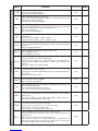
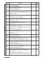
LOGICHE
TCA
Abilita o disabilita la chiusura automatica
On: chiusura automatica abilitata
Off: chiusura automatica disabilitata
(ON)
IbL
Abilita o disabilita la funzione condominiale.
On: funzione condominiale abilitata. L’impulso P.P. o del trasmettitore non ha
effetto durante la fase di apertura.
Off: funzione condominiale disabilitata.
(OFF)
SCL
Abilita o disabilita la chiusura rapida
On: chiusura rapida abilitata. Con cancello aperto o in movimento l’intervento
della fotocellula provoca la chiusura automatica dopo 3 s.
Attiva solo con TCA:ON
Off: chiusura rapida disabilitata.
(OFF)
PP
Seleziona la modalità di funzionamento del ”Pulsante P.P.” e del
trasmettitore.
On: Funzionamento: APRE > CHIUDE > APRE >
Off: Funzionamento: APRE > STOP > CHIUDE > STOP >
(OFF)
PRE
Abilita o disabilita il pre-lampeggio.
On: Pre-lampeggio abilitato. Il lampeggiante si attiva 3s prima della partenza
del motore.
Off: Pre-lampeggio disabilitato.
(OFF)
LTCA
Abilita o disabilita il lampeggiante durante il tempo TCA.
On: Lampeggiante attivo.
Off: Lampeggiante non attivo.
(OFF)
CLOC
Seleziona la modalità dell’ingresso APRE
On: Ingresso APRE con funzionalità OROLOGIO.
Da utilizzare per collegamento a temporizzatore per apertura/chiusura a
tempo. (Contatto CHIUSO- cancello aperto, Contatto aperto, funzionamento
normale).
Off: Ingresso APRE con funzionalità APRE
(OFF)
htr
Abilita o disabilita la funzione Uomo presente.
On: Funzionamento Uomo Presente.
La pressione dei pulsanti APRE/CHIUDE deve essere mantenuta durante tut-
ta la manovra.
Off: Funzionamento automatico.
(OFF)
IBCA
Abilita o disabilita i comandi PP e PED durante la fase TCA.
On: Comandi PP e PED non abilitati.
Off: Comandi PP e PED abilitati.
(OFF)
ENC
Abilita o disabilita l’Encoder. Vedi paragrafo “Modalità di funzionamento con
Encoder abilitato/disabilitato”
On: Il sensore antischiacciamento è attivato.
Off: Il sensore antischiacciamento è disattivato.
(ON)
Cvar
Abilita o disabilita i trasmettitori a codice programmabile.
On: Ricevitore radio abilitato esclusivamente ai trasmettitori a codice variabile
(rolling-code).
Off: Ricevitore abilitato a trasmettitori codice variabile (rolling-code) e pro-
grammabile (autoapprendimento e dip/switch) .
(OFF)
2ch
Abilita o disabilita il secondo canale radio sui morsetti 10/11 (utilizzabile solo
nel caso di centrali con ricevente incorporata).
On: Uscita 10/11 configurata come secondo canale radio.
La logica SERL deve essere settata in OFF.
Off: Uscita 10/11 è configurata dalla Logica SERL.
(OFF)
serL
Abilita o disabilita la funzione luce di servizio sull’uscita 10-11.
On: Ad ogni manovra il contatto viene chiuso per il tempo impostato con il
parametro TLS
Utilizzare un relè ausiliario per il comando della luce.
Off: L’uscita ha la funzione SCA, spia cancello aperto: contatto aperto ad
anta chiusa, intermittente in fase di chiusura, contatto chiuso in fase di aper-
tura e ad anta aperta. Vedi schema di collegamento.
(OFF)

8
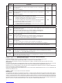
MENU FUNZIONE Valori impostabili
ON-OFF-(Default) MEMO
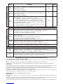
LOGICHE
TST1
Abilita o disabilita la verifica delle fotocellule sull’ingresso PHOT O.
On: Verifica abilitata. Se la verifica ha esito negativo non viene comandata nes-
suna manovra
Off: Verifica disabilitata.
(OFF)
TST2
Abilita o disabilita la verifica delle fotocellule sull’ingresso PHOT C.
On: Verifica abilitata. Se la verifica ha esito negativo non viene comandata nes-
suna manovra
Off: Verifica disabilitata.
(OFF)
PHTC
Seleziona la modalità di funzionamento dell’ingresso PHOT C.
On: Ingresso PHOT C attivo sia in apertura sia in chiusura.
In apertura: l’apertura del contatto provoca l’arresto del motore, quando la
fotocellula viene liberata, il motore riparte in apertura.
In chiusura: l’apertura del contatto provoca l’arresto del motore, quando la
fotocellula viene liberata, il motore inverte il senso di marcia (apre).
Off: Ingresso PHOT C attivo solo in chiusura.
In chiusura: l’apertura del contatto provoca l’arresto del motore e l’inversio-
ne istantanea del senso di marcia (apre).
(OFF)
MENU FUNZIONE
RADIO
PP
Selezionando questa funzione la ricevente si pone in attesa (Push) di un codice trasmettitore da assegnare
alla funzione passo-passo.
Premere il tasto del trasmettitore che si intende assegnare a questa funzione.
Se il codice è valido, viene memorizzato e viene visualizzato il messaggio OK
Se il codice non è valido, viene visualizzato il messaggio Err.
2ch
Selezionando questa funzione la ricevente si pone in attesa (Push) di un codice trasmettitore da assegnare al
secondo canale radio.
Premere il tasto del trasmettitore che si intende assegnare a questa funzione.
Se il codice è valido, viene memorizzato e viene visualizzato il messaggio OK
Se il codice non è valido, viene visualizzato il messaggio Err.
CLr
Selezionando questa funzione la ricevente si pone in attesa (Push) di un codice trasmettitore da cancellare
dalla memoria.
Se il codice è valido, viene cancellato e viene visualizzato il messaggio OK
Se il codice non è valido o non è presente in memoria, viene visualizzato il messaggio Err
RTR Cancella completamente la memoria della ricevente. Viene richiesta conferma dell’operazione.
MENU FUNZIONE
NMAN
Visualizza il numero di cicli completi (apre+chiude) effettuate dall’automazione.
La prima pressione del pulsante <PG>, visualizza le prime 4 cifre, la seconda pressione le ultime 4.
Es. <PG> 0012 >>> <PG> 3456: effettuati 123.456 cicli.
RES
RESET della centrale. ATTENZIONE!: Riporta la centrale ai valori di default.
La prima pressione del pulsante <PG> provoca il lampeggio della scritta RES, una ulteriore pressione del pul-
sante <PG> effettua il reset della centrale.
Modalità di funzionamento con Encoder abilitato/disabilitato
LOGICA ENC=ON: Il sensore antischiacciamento è attivato.
In caso di rilevamento ostacolo la centrale comanda l’arresto del movimento ed un inversione per circa 3s.
Regolare la sensibilità tramite i parametri SEAV e SEAR in conformità con le normative vigenti.
Anche una accurata regolazione del freno motore (parametro IBRA) può contribuire al rispetto delle normative di sicurezza.
Rallentamento
Con il parametro TSM superiore a 0 (rallentamento attivato) la centrale eseguirà i rallentamenti utilizzando l’Encoder come sensore di
posizione. La prima manovra viene effettuata a velocità normale senza rallentamenti per l’apprendimento della corsa.
Registrata la corsa la centrale gestirà in modo automatico le fasi di rallentamento in apertura e chiusura. Lo spazio di rallentamento
può essere aumentato o diminuito dal parametro TSM.
Questa fase di apprendimento viene effettuata anche in caso di interruzione dell’alimentazione di rete o in caso di attivazione del
rallentamento (TSM da 0 a >0)
LOGICA ENC=OFF: il sensore antischiacciamento è disattivato.
Rallentamento
Con il parametro TSM superiore a 0 (rallentamento attivato), la centrale eseguirà i rallentamenti calcolando la durata della manovra.
Se la prima manovra ha inizio da una posizione di finecorsa, la centrale esegue una manovra completa a velocità normale, dalla ma-
novra successiva inizierà ad eseguire i rallentamenti in apertura e chiusura. Nel caso la manovra inizi da una posizione intermedia, la
centrale si porterà al finecorsa con velocità normale, quindi eseguirà una manovra a velocità normale fino alla posizione intermedia
precedente, per poi procedere a velocità ridotta fino a finecorsa. Solo dopo questa procedura la centrale eseguirà i rallentamenti in
apertura e chiusura. Lo spazio di rallentamento può essere aumentato o diminuito dal parametro TSM.

9
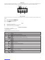
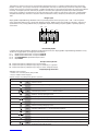
Diagnostica
Nel caso di anomalie di funzionamento è possibile visualizzare, premendo il tasto + o -, lo stato di tutti gli ingressi (finecorsa, coman-
do e sicurezza). Ad ogni ingresso è associato un segmento del display che in caso di attivazione si accende, secondo il seguente
schema.
PHOT 0
SWC
STOP
SWO
PHOT C DAS
P.P. PED OPEN CLOSE
Messaggi di errore
La centrale verifica il corretto funzionamento dei dispositivi di sicurezza. In caso di malfunzionamento possono essere visualizzati
dal display i seguenti messaggi:
ERR1 Errore verifica fotocellule sull’ingresso PHOT O.
ERR2 Errore verifica fotocellule sull’ingresso PHOT C.
ERR3 Errore ENCODER/controllare fusibile F3
ERR4 Errore TRIAC
Fusibili
F1 Fusibile di protezione trasformatore
F2 Fusibile protezione uscita accessori e segnali
F3 Fusibile di protezione uscita motore e lampeggiante
Esempio programmazione
Supponiamo sia necessario:
- impostare un tempo di chiusura automatica (TCA) di 100s
- attivare il prelampeggio
eseguire passo a passo le operazioni descritte di seguito:
Passo Premere Display Note
1PAR Primo menu
2TCA Prima funzione del primo menu
3040 Valore attualmente impostato per la funzione selezionata
4100 Settare con i tasti <+> e <-> il valore desiderato
5PRG Il valore viene programmato
TCA Effettuata la programmazione, il display si riporta alla funzione appena settata
6PAR Premere simultaneamente <+> e <-> per spostarsi al menu superiore
7Log Secondo menu
8TCA Prima funzione del secondo menu
9Pre Premere più volte <-> fino a selezionare la logica PRE
10 OFF Valore attualmente impostato per la funzione selezionata
11 ON Settare con i tasti <+> e <-> il valore desiderato
12 PRG Il valore viene programmato
Pre Effettuata la programmazione, il display si riporta alla funzione appena settata
13 PAR Premere simultaneamente <+> e <-> per tornare al menu superiore e uscire dalla programma-
zione o attendere 30s.

10
EC declaration of confirmity
Manufacturer: Automatismi Benincà SpA.
Address: Via Capitello, 45 - 36066 Sandrigo (VI) - Italia
Herewith declares that: control unit CP.BULL / CP.BULL-RI / MATRIX / MATRIX-RE.
complies with the following relevant provisions:
EMC guidelines: 89/336/CCE, 93/68/CEE
Low voltage guidelines: 73/23/CEE, 93/68/CEE
Benincà Luigi, Legal responsible.
Sandrigo, 08/08/2008.
WARNINGS
This manual has been especially written to be use by qualified
fitters.
None of the information provide in this manual can be consi-
dered as being of interest for the end users.
Preserve this manual for future needs.
The technician has to furnish all the information related to the
step by step function, the manual and the emergency function
of the operator, and to deliver the manual to the final user.
•Foresee on the supply net an onnipolar switch or
selector with distance of the contacts equal or
superior to 3 mms.
Verify that of the electrical system there is an awry differential
interrupter and overcurrent protection.
Some typologies of installation require the connection of the
shutter to be link at a conductive mass of the ground according
to the regulations in force.
The electrical installation and the operating logic must comply
with the regulations in force.
The leads fed with different voltages must be physically
separate, or they must be suitably insulated with additional
insulation of at least 1 mm.
The leads must be secured with an additional fixture near
the terminals.
During installation, maintenance and repair, interrupt the
power supply before opening the lid to access the electrical
parts
Check all the connections again before switching on the
power.
The unused N.C. inputs must be bridged.
The descriptions and the present illustrations in this manual
are not binding. Leaving the essential characteristics of the
product unchanged, the manufacturer reserves himself the
right to bring any change of technical, constructive or com-
mercial character without undertaking himself to update the
present publication.
TECHNICAL DATA
Power supply 230 Vac 50/60 Hz
Output supply 1 motor 230Vac
Power maximum motor
1000 W
Output supply accessories
24Vdc 500mA max.
Protection level
IP54
Operating temp.
-20°C / +70°C
Radio receiver CP.BULL-RI / MATRIX:
built in 433,92 MHz confgurabile (rolling-code or
programmable + rolling-code)
CP.BULL / MATRIX-RE:
removable connector for radio receiver
Rolling code transmitters supported
64
It is provided with “Single fault test” function, in compliance with the Machinery Directive 98/37/EC.

11
MATRIX/CP.BULL Control Unit
INPUT/OUTPUT FUNCTIONS
Terminal No. Function Description
1-2 Power supply Input, 230Vac 50Hz (1-Phase/2-Neutral)
3 GND Connection to ground (compulsory)
4-5 Aerial Connection of the insertable radio receiver card (4-signal/5-display).
6-7 RX 2° Ch Output, second radio channel of the receiver. N.O. voltage-free contact.
This output is not available in CP.BULL-RI and MATRIX control units with built-in receiver.
8-9 24Vac Output: power supply of accessories, 24Vac/500mA max.
10-11 SCA o
Service light
Normally Open (N.O.) free contact. Configuration like SCA (open gate warning LED) or timed
service light (see SERL Logic).
In CP.BULL-RI and MATRIX control units with built-in receiver, this contact can be preset as
output of second radio contact (see 2ChLogic).
12-13 PHOTO TEST N.O. free contact. It is used to power photocell transmitters in TEST operating mode.
See diagram “Connection of tested safety devices” and TST1 and TST2 Logic.
14 COM Common for control inputs.
15 OPEN Input, OPEN push-button (N.O. contact).
16 CLOSE Input, CLOSE push-button (N.O. contact)
17 Step-by-Step Input, step-by-step push-button (N.O. contact)
18 PED
Input, pedestrian push-button (N.O. contact). It controls the partial opening. Configuration is
through parameter TPED. When TCA time has elapsed (if activated) a closure control signal
is sent.
19 COM Common, for limit switches and safety devices
20 STOP Input, STOP push-button (N.C. contact)
21 PHOT O
Input, (N.C. contact) for safety devices (e.g. photocells).
In the closing phase: the contact opening causes the motor stop. Common: when the photo-
cell is released, the motor inverts the movement direction (open).
In the opening phase: the contact opening causes the motor stop. When the photocell is
released, the motor re-starts the opening operation.
22 SWO Input, OPEN limit switch (N.C. contact)
23 SWC Input, CLOSE limit switch (N.C. contact)
24 PHOT C
Input (N.C. contact) for safety devices (e.g. photocells).
In the closing phase: Configuration through PHTC Logic.
In the opening phase: Configuration through PHTC Logic.
25-26 DAS
Input, safety edge
Resistive edge: “DAS” Jumper closed
Mechanical edge: “DAS” Jumper open
When the edge is activated, the gate movement is stopped and reversed for about 3s.
If the edge is not in use: “DAS” Jumper open, 25-26 terminals are short-circuited.
27-28-29 Motor Connection of motor 230Vac - single-phase:
27-Phase/28-Common/29-Phase
27-30 Capacitor Connection of capacitor
31-32 Blinker Connection of blinker, 230Vac 40W max.
To check connections:
1) Cut-off power supply.
2) Manually release the wing, move it to approx. half-stroke and lock it again.
3) Reset power supply.
4) Send a step-by-step control signal by pressing the button or the remote control key.
5) The wing should start an opening movement. If this is not the case, invert the movement wires (27< >29) of the motor and the
limit switch wires SWO-SWC (22< >23).
6) Cut-off and restore power supply.
Programming
The programming of the various functions of the control unit is carried out using the LCD display on the control unit and setting
the desired values in the programming menus described below.
The parameters menu allows you to assign a numerical value to a function, in the same way as a regulating trimmer.
The logic menu allows you to activate or deactivate a function, in the same way as setting a dip-switch.
Other special functions follow the parameters and logic menus and may vary depending on the type of control unit or the software
release.
The CP.BULL-RI and MATRIX control units are equipped with a built-in radio module to receive both
fixed code and variable code control signals with a frequency of 433.92MHz, able to store up to 64 different codes in memory.
The RADIO menu and the 2Ch and CVAR logic are available in these control units only.

12
The CP.BULL and MATRIX-RE control units are equipped with connector for extractable receiver.
To access programming:
1 Press the button <PG>, the display goes to the first menu, Parameters “PAR”.
2 With the <+> or <-> button, select the menu you want (PAR>>LOG>>RADIO>>NMAN>>RES)
3 Press the button <PG>, the display shows the first function available on the menu.
4 With the <+> or <-> button, select the function you want.
5 Press the button <PG>, the display shows the value currently set for the function selected.
6 With the <+> or <-> button, select the value you intend to assign to the function.
7 Press the button <PG>, the display shows the signal “PRG” which indicates that programming has been completed.
Notes:
Simultaneously pressing <+> and <-> from inside a function menu allows you to return to the previous menu without making any
changes.
Simultaneously pressing <+> and <-> when the display is switched off shows the card software release.
Hold down the <+> key or the <-> key to accelerate the increase/decrease of the values.
After waiting 30s the control unit quits programming mode and switches off the display.
Parameters, Logic and Special Functions
The tables below describe the individual functions available in the control unit.
MENU FUNCTION Settable values
MIN-MAX-(Default) MEMO
PARAMETERS
TCA Automatic closure time. It is activated only with “TCA”=ON logic.
At the end of the preset time, the control unit controls a closure operation. 1-240-(40s)
Tped The passage left open by the gate leaf during the partial opening (pedestrian)
is adjusted.This value is expressed in decimetres. 2-100-(5dm)
Tsm
The area covered by the gate during the braking phase is adjusted.
0 = braking disabled. The performance of the automatic system during the first
operations depends on the ENC logic.
See section “Operating mode with enabled/disabled Encoder”.
0-100-(0%)
PMo The torque applied to the motor in the opening phase is adjusted.* 1-99-(50%)
PMC The torque applied to the motor in the closing phase is adjusted *. 1-99-(50%)
Pso
The torque applied to the motor during braking in the closing phase is adjusted.*
1-99-(50%)
Psc
The torque applied to the motor during braking in the opening phase is adjusted *
1-99-(50%)
SeaU
The intervention threshold of the anti-crashing device (Encoder) during the
phase at normal speed is adjusted.*
0:Off-1:maximum sensitivity - 99: minimum sensitivity
0-99-(0%)
SEAR
The intervention threshold of the anti-crashing device (Encoder) during braking
is adjusted *.
0:Off-1:maximum sensitivity - 99: minimum sensitivity
0-99-(0%)
TLS Activated only with SERL:ON Logic. The activation time of the service light is
adjusted. 1-240-(60s)
Ibra The force of the motor brake is adjusted.
0: disabled braking - 1:minimum braking - 99: maximum braking 0-99-(50%)
TM
It is activated only with SERL logics EN : OFF.
Operating time. The operating time is adjusted at normal speed
during motor opening and closing phases.
1-250-(90s)
BLC
Motor stop delay on limit switch. It is activated only with enabled braking
(TSM).
The motor stop delay is adjusted after the triggering of the limit switch. Use a
value calibrated on the gate weight. Use these indicative values:
0 deactivated (no delay)
1 very heavy gates (short delay)
2 heavy gates
3 average gates
4 light gates (longer delay)
0-4 (0)
* WARNING:
An incorrect setting of these parameters may result in a danger. Comply with regulations in force!

13
MENU FUNCTION Settable values
ON-OFF-(Default) MEMO
LOGIC
TCA
The automatic closure is enabled or disabled
On: enabled automatic closure
Off: disabled automatic closure
(ON)
IbL
The multi-flat function is enabled or disabled.
On: enabled multi-flat function. The P.P. (Step-by-step) impulse or the
impulse of the transmitter have no effect in the opening phase.
Off: disabled multi-flat function.
(OFF)
SCL
The rapid closure is enabled or disabled
On: rapid closure is enabled. When the gate is open or moving, the photo-
cell activation causes the automatic closure of the gate after 3 s. It is acti-
vated only with TCA:ON
Off: rapid closure is disabled.
(OFF)
PP
The operating mode of “P.P. Push button” and of the transmitter are
selected.
On: Operation : OPEN > CLOSE > OPEN >
Off: Operation: OPEN > STOP > CLOSE > STOP >
(OFF)
PRE
Forewarning flashing light enabled or disabled.
On: enabled forewarning flashing light. The flashing light is activated 3 s
before the starting of the motor.
Off: disabled forewarning flashing light.
(OFF)
LTCA
During the TCA time, the blinker is enabled or disabled.
On: Activated blinker.
Off: De-activated blinker.
(OFF)
CLOC
The OPEN input mode is selected
On: OPEN input with WATCH function.
To be used for the connection of timed opening/closing. (CLOSED contact
- open gate. OPEN contact - normal operation).
Off: OPEN input with OPEN function.
(OFF)
htr
The Operator function is enabled or disabled.
On: Operator function enabled.
During operation, the OPEN/CLOSE push-buttons must be kept pressed.
Off: Automatic operation.
(OFF)
IBCA
During the TCA phase, the PP and PED controls are enabled or disabled.
On: PP and PED controls are disabled.
Off: PP and PED controls are enabled.
(OFF)
ENC
The Encoder is enabled or disabled. See section “Operating mode with ena-
bled/disabled Encoder”
On: Encoder enabled – The anti-crash sensor is activated.
Off: Encoder disabled – The anti-crash sensor is deactivated.
(ON)
Cvar
The code programmable transmitters is enabled or disabled.
On: Radio receiver enabled only for rolling-code transmitters.
Off: Receiver enabled for rolling-code and programmable code transmitters
(self-learning and Dip Switch).
OFF
2ch
The second radio channel is enabled or disabled on terminals 10/11 (it can
be used only for control units with built-in receiver).
On: 10/11 output, preset as second radio channel.
The SERL logic should be OFF.
Off: 10/11 output, preset by the SERL Logic.
(OFF)
serL
The service light function to output 10-11 is enabled or disabled.
On: At every operation, the contact is closed for the time preset with TLS
parameter
Use the auxiliary relay to control the light.
Off: the output is provided with SCA function, open gate LED: open contact
with closed gate - flashing light in closing phase - closed contact in opening
phase and open gate. See wire diagram.
(OFF)

14
MENU FUNCTION Settable values
ON-OFF-(Default) MEMO
LOGIC
TST1
The test of photocells to PHOT O input is enabled or disabled.
On: Test is enabled. If the test is negative, no operation is performed.
Off: Test is disabled.
(OFF)
TST2
The test of photocells to PHOT C input is enabled or disabled.
On: Test is enabled. If the test is negative, no operation is performed.
Off: Test is disabled.
(OFF)
PHTC
The operating mode of the PHOT C input is selected.
On: PHOT C input is activated in both opening and closing phases.
In the opening phase: the contact opening causes the motor stop. When the
photocell is released, the motor restarts in the opening phase.
In closing phase: the contact opening causes the motor stop. When the
photocell is released, the motor inverts the movement direction (open).
Off: The PHOT C input is activated in the closing phase only.
In the closing phase: the contact opening causes the motor stop and the
immediate reversion of the operation direction (open).
(OFF)
MENU FUNCTION
RADIO
PP
By selecting this function, the receiver awaits (Push) for a transmitter code to be assigned to the step-by-step
function.
Press the transmitter key to be assigned to this function.
If the code is valid, it is stored in memory and OK appears.
If the code is not valid, the wording Err is displayed.
2ch
By selecting this function, the receiver awaits (Push) for a transmitter code to be assigned to the second radio
channel.
Press the transmitter key to be assigned to this function.
If the code is valid, it is stored in memory and OK appears.
If the code is not valid, the wording Err is displayed.
CLr
By selecting this function, the receiver awaits (Push) for a transmitter code to be erased from memory.
If the code is valid, it is erase and OK appears.
If the code is not valid or is not in memory, the wording Err is displayed.
RTR Completely erase the receiver memory. Confirmation of operation is required.
MENU FUNCTION
NMAN
Displays the number of complete cycles (open+close) carried out by the automation.
When the <PG> button is pressed for the first time, it displays the first 4 figures, the second time it shows the
last 4. Example <PG> 0012 >>> <PG> 3456: made 123.456 cycles.
RES
RESET of the control unit. ATTENTION!: Returns the control unit to the default values.
Pressing the <PG> button for the first time causes blinking of the letters RES, pressing the <PG> button again
resets the control unit.
Note: The transmitter codes are not erased from the receiver.
Operating mode with enabled/disabled Encoder
ENC LOGICS =ON: anti-crash sensor activated.
If an obstacle is detected, the control unit will control the movement stop and a movement reversion of about 3s.
Adjust sensitiveness through parameters SEAV and SEAR, in compliance with regulations in force.
An accurate adjustment of the motor brake (IBRA parameter) can help to comply with safety regulations in force.
Braking
With TSM parameter higher than 0 (activated braking), the control unit carries out braking by using the Encoder as position sensor.
The first operation is carried out at regular speed, without braking, so as to allow the control unit to learn the stroke length.
Once the stroke has been recorded, the control unit will be able to automatically manage braking phases in both opening and clos-
ing phases. The braking space can be increased or decreased through TSM parameter.
This learning phase is carried out also in case of power failure or when braking is activated (TSM parameter is modified from 0 to a
value higher than 0)
ENC LOGICS =OFF: anti-crash sensor deactivated.
Braking
With TSM parameter higher than 0 (activated braking), the control unit carries out braking by calculating the operating time.
If the first operation starts from a limit switch position, the control unit carries out a complete operation at optimal speed. Braking in
opening and closing phases will start with the following operation. If the operation starts from an intermediate position, the control
unit reaches the limit switch position at normal speed. An operation will be carried out at regular speed until the previous intermedi-
ate position is reached, and then the system will continue its stroke at reduced speed until the limit switch is reached.
The control unit will carry out braking in both opening and closing phases only after this procedure. Braking space can be increased
or decreased through TSM parameter.

15
Diagnostics
In the event of malfunctions, by pressing key + or - the status of all inputs (limit switches, control and safety) can be displayed. One
segment of the display is linked to each input. In the event of failure it switches on according to the following scheme.
PHOT 0
SWC
STOP
SWO
PHOT C DAS
P.P. PED OPEN CLOSE
Error messages
The control unit checks the correct operation of the safety devices. In case of failure, the following messages may appear on the
display:
ERR1 Error, check photocells at PHOT O input.
ERR2 Error, check photocells at PHOT C input.
ERR3 Error, ENCODER/ check fuse F3
ERR4 Error, TRIAC
Fuses
F1 Protection fuse of transformer
F2 Output protection fuse of accessories and signals
F3 Output protection fuse for motor and blinker
Example of programming
Let us suppose it is necessary to:
- set an automatic closing time (TCA) of 100s
- activate pre-blinking
Perform the operations described below step by step:
Step Press Display Notes
1PAR First menu
2TCA First function of the first menu
3040 Value currently set for the function selected
4100 Set the desired value with the <+> and <-> keys
5PRG The value is programmed
TCA When programming has been made, the display goes to the function just set
6PAR Press <+> and <-> simultaneously to go to the higher menu
7Log Second menu
8TCA First function of the second menu
9Pre Press <-> several times to select PRE logic
10 OFF Value currently set for the function selected
11 ON Set the desired value with the <+> and <-> keys
12 PRG The value is programmed
Pre When programming has been made, the display goes to the function just set
13 PAR Press <+> and <-> simultaneously to go to the higher menu and quit programming or wait
30s.

16
EG-Konformitatserklarung
Hersteller: Automatismi Benincà SpA.
Adresse: Via Capitello, 45 - 36066 Sandrigo (VI) - Italia
Hiermit erklaren wir, dass: Steuereinheit CP.BULL / CP.BULL-RI / MATRIX / MATRIX-RE.
folgenden einschlagigen Bestimmungen entspricht:
EMV-Richtlinie: 89/336/CCE, 93/68/CEE
Tiefe Spannung Richtlinie: 73/23/CEE, 93/68/CEE
Benincà Luigi, Rechtsvertreter
Sandrigo, 08/08/2008.
HINWEISE
Dieses Handbuch ist ausschließlich qualifiziertem Personal
für die Installation und Wartung von automatischen Öffnung-
svorrichtungen bestimmt.
Es enthält keine Informationen die für den Endbenutzer inte-
ressant oder nützlich sein könnten.
Bewahren Sie dieses Handbuch für Nachschlagzwecke auf.
Der Installateur hat dem Benutzer alle Informationen über den
automatischen, manuellen und Not-Betrieb der Automatik
zusammen mit der Bedienungsanleitung zu liefern.
•Das Stromnetz muss mit einem allpoligen Schalter
bzw. Trennschalter ausgestattet sein, dessen Kon-
takte einen Öffnungsabstand gleich oder größer
als 3 aufweisen.
Kontrollieren ob der elektrischen Anlage ein geeigneter
Differentialschalter und ein Überspannungsschutzschalter
vorgeschaltet sind
Einige Installationstypologien verlangen den Anschluss
des Flügels an eine Erdungsanlage laut den geltenden
Sicherheitsnormen.
Die elektrische Installation und die Betriebslogik müssen den
geltenden Vorschriften entsprechen.
Die Leiter die mit unterschiedlichen Spannungen gespeist
werden, müssen physisch getrennt oder sachgerecht mit
einer zusätzlichen Isolierung von mindestens 1 mm isoliert
werden.
Die Leiter müssen in der Nähe der Klemmen zusätzlich be-
festigt werden.
Während der Installation, der Wartung und der Reparatur, die
Anlage stromlos machen bevor an den elektrischen Teilen
gearbeitet wird.
Alle Anschlüsse nochmals prüfen, bevor die Zentrale mit
Strom versorgt wird.
Die nicht verwendeten N.C. Eingänge müssen überbrückt
werden.
Die in diesem Handbuch enthaltenen Beschreibungen und
Abbildungen sind nicht verbindlich. Ausgenommen der
Haupteigenschaften des Produkts, behält sich der Hersteller
das Recht vor eventuelle technische, konstruktive oder kom-
merzielle Änderungen vorzunehmen ohne dass er vorliegende
Veröffentlichung auf den letzten Stand bringen muss.
TECHNISCHE DATEN
Stromversorgung 230 Vac 50/60 Hz
Motorausgang 1 motor 230Vac
Maximale Motorenleistung
1000 W
Ausgang Speisung Zubehör
24Vdc 500mA max.
Schutzklasse
IP54
Betriebstemperatur
-20°C / +70°C
Funkempfänger CP.BULL-RI / MATRIX:
433,92 MHz eingebaut und konfigurierbar (Rolling-
Code oder fest+Rolling-Code)
CP.BULL / MATRIX-RE:
steckverbinder für Funkempfänger
Programmierbare Codes
64
Sie bietet die Prüffunktion “Test einzelner Störungen„ laut Maschinenrichtlinie 98/37/CE.

17
Steuereinheit MATRIX/CP.BULL
FUNKTIONEN DER EIN-/AUSGÄNGE
Klemmen Funktion Beschreibung
1-2 Speisung Eingang 230Vac 50Hz (1-Phase/2-Nulleiter)
3 GND Zur Erdung (vorgeschrieben)
4-5 Antenne Anschluss Antenne der Karte des steckbaren Funkempfängers (4-Signal/5-Schirm).
6-7 RX 2° Ch Ausgang zweiter Funkkanal. Spannungsfreier Kontakt N.O..
Nicht für Zentralen CP.BULL-RI und MATRIX mit eingebautem Empfänger verfügbar.
8-9 24Vac Ausgang Speisung Zubehör 24Vac/500mA max.
10-11 SCA oder
Dienstlicht
Reiner Kontakt N.O. Als SCA konfigurierbar (grüne Leuchte Tor offen) oder zeitgesteuertes
Dienstlicht (siehe Logik SERL)
Bei den Zentralen CP.BULL-RI und MATRIX mit eingebautem Empfänger, kann dieser Kontakt als
Ausgang des zweiten Funkkanals (siehe Logik 2Ch) konfiguriert werden.
12-13 PHOTO TEST
Reiner Kontakt N.O. Wird verwendet um die Sendegeräte der Fotozellen im Modus TEST zu
speisen.
Siehe Schema „Anschluss geprüfter Sicherheitsvorrichtungen“ und Logik TST1 und TST2.
14 COM Gemein für alle Steuerungseingänge.
15 OPEN Eingang Taste ÖFFNEN (Kontakt N.O.)
16 CLOSE Eingang Taste SCHLIESSEN (Kontakt N.O.)
17 Schritt-Schritt Eingang Taste Schritt-Schritt (Kontakt N.O.)
18 PED Eingang Taste Fußgänger (Kontakt N.O.), steuert das teilweise Öffnen,als Parameter TPED konfi-
gurierbar. Wenn die Zeit TCA (wenn aktiv) abgelaufen ist, wird das Schließen gesteuert.
19 COM Gemein für Endschalter und Sicherheiten
20 STOP Eingang Taste STOP (Kontakt N.C.)
21 PHOT O
Eingang (Kontakt N.C.) für Sicherheitsvorrichtungen (z.B. Fotozellen)
Beim Schließen: das Öffnen des Kontakts hat das Anhalten des Motors zur Folge wenn die Foto-
zelle freigesetzt wird, schaltet der Motor die Betriebsrichtung um (öffnet).
Beim Öffnen: das Öffnen des Kontakts hat das Anhalten des Motors zur Folge wenn die Fotozelle
freigesetzt wird, schaltet der Motor wieder zum Öffnen ein.
22 SWO Eingang Endschalter ÖFFENEN (Kontakt N.C.)
23 SWC Eingang Endschalter SCHLIESSEN (Kontakt N.C.)
24 PHOT C
Eingang (Kontakt N.C.) für Sicherheitsvorrichtungen (z.B. Fotozellen)
Beim Schließen: Verhalten durch Logik PHTC konfigurierbar.
Beim Öffnen: Verhalten durch Logik PHTC konfigurierbar.
25-26 DAS
Eingang Kontakt Näherungsflanke
Widerstandsfähige Flanke Jumper “DAS” geschlossen
Mechanische Flanke Jumper “DAS” geöffnet
Das Einschalten der Flanke hält die Bewegung des Flügels an und schaltet ca. 3 sec. lang um.
Wird die Flanke nicht verwendet: Jumper „DAS“ geöffnet, Brücke zwischen den Klemmen 25-26.
27-28-29 Motor Anschluss an den Motor 230Vac – einphasig: 27-Phase/28-Gemein/29-Phase
27-30 Kondensator Anschluss Kondensator
31-32 Blinkleuchte Anschluss Blinkleuchte 230Vac 40W max.
Anschlüsse überprüfen:
1) Stromversorgung abtrennen.
2) Von Hand Torflügel entsichern, bis auf halbem Hub führen und wieder blockieren.
3) Wieder Strom geben.
4) Einen Schritt-Schritt-Befehl über die Taste oder die Fernsteuerung geben.
5) Der Torflügel muss sich öffnen. Anderenfalls die Leiter für den Betrieb (27< >29) des Motors und die Leiter des Endschalters
SWO-SWC (22< >23) umkehren.
1) Stromversorgung abtrennen.
6) Stromversorgung abtrennen. Stromversorgung wieder herstellen.
Programmierung
Die Programmierung der verschiedenen Funktionen der Steuerzentrale erfolgt über das LCD-Display an der Zentrale selbst, indem
die gewünschten Werte in den nachstehend beschriebenen Programmierungs-Menüs eingegeben werden. Das Parameter-Menü
ermöglicht die Eingabe eines numerischen Werts mit einer Funktion, analog wie ein Regeltrimmer.
Das Logik-Menü ermöglicht das Aktivieren oder Deaktivieren einer Funktion, analog zum Einstellen eines Dip-Switch. Andere
Sonderfunktionen folgen dem Parameter- und Logik-Menü und können ja nach Typ der Steuerzentrale oder der Software-Version
variieren.
Die Zentralen CP.BULL-RI und MATRIX sind mit einem eingebauten Funkmodul zum Empfang von Fernbedienungen mit festem
oder variablen Code mit einer Frequenz von 433.92MHz ausgestattet, die bis zu 64 unterschiedliche Codes speichern können.
Das Menü FUNK und die Logik 2Ch und CVAR sind nur für diese Zentralen geeignet.

18
Die Zentralen CP.BULL und MATRIX-RE sind mit Verbinder für den steckbaren Empfänger ausgestattet.
Für den Zugriff auf die Programmierung:
1 Die Taste <PG> drücken, das Display stellt sich auf das erste Parameter-Menü “PAR”.
2 Mit der Taste <+> oder <-> das gewünschte Menü selektieren (PAR>>LOG>>RADIO>>NMAN>>RES).
3 Die Taste <PG> drücken, am Display wird die erste Funktion des Menüs sichtbar.
4 Mit der Taste <+> oder <-> die gewünschte Funktion selektieren.
5 Die Taste <PG> drücken, am Display wird der derzeitig für die selektierte Funktion eingestellte Wert sichtbar.
6 Mit der Taste <+> oder <-> den für die Funktion gewünschten Wert selektieren.
7 Die Taste <PG> drücken, am Display wird das Signal “PRG” sichtbar, welches die erfolgte Programmierung anzeigt.
Anmerkungen:
Durch gleichzeitiges Drücken von <+> und <->, innerhalb eines Funktionen-Menüs, wird zum vorherigen Menü zurückgekehrt, ohne
Änderungen durchzuführen.
Durch gleichzeitiges Drücken von <+> und <->, bei ausgeschaltetem Display, wird die Software-Version der Platine angezeigt.
Durch gedrückt halten der Taste <+> oder der Taste <-> wird das zunehmende oder abnehmende Ablaufen der Werte beschleunigt.
Nach einer Wartezeit von 30s verlässt die Steuerzentrale den Programmiermodus und das Display schaltet sich aus.
Parameter, Logiken und Sonderfunktionen
In den folgenden Tabellen werden die einzelnen Funktionen der Steuerzentrale beschrieben.
MENÜ FUNKTION Einstellbare Werte
MIN-MAX-(Default) MEMO
PARAMETER
TCA Zeit für das automatische Schließen Aktiv nur mit Logik „TCA“= ON
Wenn die eingestellte Zeit abgelaufen ist, steuert die Zentrale das Schließen. 1-240-(40s)
Tped Regelt den Weg des Flügels wenn dieser teilweise geöffnet wird (Fußgänger)
Der Wert wird in Dezimeter ausgedrückt. 2-100-(5dm)
Tsm
Regelt den Weg in der Soft Stop Phase 0= Soft Stop deaktiviert
Das Verhalten der Automatik ist während der ersten Bewegungen von der
Logik ENC abhängig.
Siehe Paragraph „Betriebsweise mit aktiviertem/deaktiviertem Encoder“.
0-100-(0%)
PMo Regelt das für den Motor angelegte Drehmoment beim Öffnen*. 1-99-(50%)
PMC Regelt das für den Motor angelegte Drehmoment beim Schließen.* 1-99-(50%)
Pso Regelt das für den Motor angelegte Drehmoment während der Geschwindig-
keitsabnahme beim Öffnen.* 1-99-(50%)
Psc Regelt das für den Motor angelegte Drehmoment während der Geschwindig-
keitsabnahme beim Schließen.* 1-99-(50%)
SeaU
Regelt die Empfindlichkeit der Kraftabschaltung (Encoder) während der norma-
le Laufgeschwindigkeit*
0:Off - 1: Maximale Empfindlichkeit - 99=mindeste Empfindlichkeit
0-99-(0%)
SEAR Regelt die Empfindlichkeit der Kraftabschaltung (Encoder) in Soft Lauf
0:Off - 1: Maximale Empfindlichkeit - 99=mindeste Empfindlichkeit 0-99-(0%)
TLS Aktiv nur mit Logik SERL: ON Regelt die Aktivierungsdauer der externer Be-
leuchtung 1-240-(60s)
Ibra Regelt die Kraft der Motorenbremse.
0: Bremsen deaktiviert – 1: mindeste Bremsung – 99: maximale Bremsung 0-99-(50%)
tm
Nur mit Logik ENC:OFF aktiv.
Anschluss an den Motor. Regelt die Betriebszeit mit normaler Geschwindigkeit
während des Öffnens und Schließens des Motors.
1-250-(90s)
BLC
Motorstopp-Verzögerung am Endschalter. Nur aktiv, wenn die Geschwindig-
keitsabnahme (TSM) aktiviert worden ist.
Regelt die Motorstopp-Verzögerungszeit nach dem Einschalten des Endschal-
ters. Einen Wert einrichten, der proportional zum Torgewicht ist. Die Richt-
werte sind:
0 deaktiviert (ohne Verzögerung)
1 sehr schwere Tore (kurze Verzögerung)
2 schwere Tore
3 mittelschwere Tore
4 leichte Tore (längere Verzögerung)
0-4 (0)
* ACHTUNG:
Eine falsche Einstellung dieser Parameter kann gefährlich sein.
Die geltenden Vorschriften beachten!

19
MENÜ FUNKTION Einstellbare Werte
ON-OFF-(Default) MEMO
LOGIKEN
TCA
Aktiviert oder deaktiviert den automatischen Schließvorgang.
On: automatischer Schließvorgang aktiviert
Off: automatischer Schließvorgang deaktiviert
(ON)
IbL
Aktiviert oder deaktiviert die Funktion Wohngemeinschaft.
On: Funktion Wohngemeinschaft aktiviert. Auf den Öffnungsvorgang haben
weder der Schritt-Schritt-Impuls noch der Impuls des Sendegeräts Einfluss.
Off: Funktion Wohngemeinschaft deaktiviert.
(OFF)
SCL
Aktiviert oder deaktiviert den schnellen Schließvorgang.
On: schnelles Schließen aktiviert Bei offenem oder sich bewegenden Tor hat
das Einschalten der Fotozelle das automatische Schließen nach 3 s. zur Folge
Aktiv nur mit TCA:ON
Off: schnelles Schließen deaktiviert
(OFF)
PP
Wählt die Betriebsweise der “Taste P.P.” und des Sendegeräts.
On: Betrieb: ÖFFNEN > SCHLIESSEN > ÖFFNEN
Off: Betrieb: ÖFFNEN > STOP > SCHLIESSEN > STOP >
(OFF)
PRE
Aktiviert oder deaktiviert das Vorblinken.
On: Vorblinken aktiviert Das Vorblinken beginnt 3 sec. vor dem Einschalten
des Motors.
Off: Vorblinken deaktiviert
(OFF)
LTCA
Aktiviert oder deaktiviert das Blinklicht während der Zeit TCA
On: Blinklicht aktiv:
Off: Blinklicht nicht aktiv.
(OFF)
CLOC
Wählt die Betriebsweise des Eingangs ÖFFNEN
On: Eingang ÖFFNEN mit UHR Funktion
Für den Anschluss mit dem Zeitgeber für das zeitgesteuerte Öffnen/Schließen
zu verwenden. (Kontakt GESCHLOSSEN – Tor offen, Kontakt geöffnet, nor-
maler Betrieb).
Off: Eingang ÖFFNEN mit Funktion ÖFFNEN
(OFF)
htr
Aktiviert oder deaktiviert die Funktion “Mann vorhanden”.
On: Betrieb im Modus „Mann vorhanden“
Die Taste ÖFFNEN/SCHLIESSEN muss während der gesamten Dauer der
Steuerung gedrückt bleiben.
Off: Automatischer Betrieb.
(OFF)
IBCA
Aktiviert oder deaktiviert die Steuerungen PP und PED während der Phase
TCA.
On: Steuerungen PP und PED nicht aktiviert.
Off: Steuerungen PP und PED aktiviert.
(OFF)
ENC
Aktiviert oder deaktiviert den Encoder. Siehe Paragraph „Betriebsweise mit
aktiviertem/deaktiviertem Encoder“.
On: Encoder aktiviert - Der Quetschsicherheitssensor ist aktiviert.
Off: Encoder deaktiviert - Der Quetschsicherheitssensor ist deaktiviert.
(ON)
Cvar
Aktiviert oder deaktiviert die Sendegeräte mit programmierbarem Code.
On: Funkempfänger ist nur für Sendegeräte mit variablem Code aktiviert (Rol-
ling-Code).
Off: Funkempfänger ist für Sendegeräte mit variablem Code (Rolling-Code)
und programmierbare (Selbstlernfunktion und Dip-Schalter) Sendegeräte ak-
tiviert.
(OFF)
2ch
Aktiviert oder deaktiviert den zweiten Funkkanal an den Klemmen 10/11 (nur
für Zentralen mit eingebautem Empfänger).
On: Ausgang 10/11 als zweiter Funkkanal konfiguriert.
Die Logik SERL muss auf OFF geschaltet sein.
Off: Ausgang 10/11 ist als Logik SERL konfiguriert.
(OFF)
serL
Aktiviert oder deaktiviert die Funktion Dienstlicht am Ausgang 10-11.
On: Bei jeder Schaltung wird der Kontakt für die mit dem Parameter TLS ein-
gestellte Zeit geschlossen.
Ein Hilfsrelais für die Lichtsteuerung verwenden.
Off: Der Ausgang hat die Funktion SCA, Meldeleuchte Tor offen: offener Kon-
takt bei geschlossenem Flügel, aussetzend während der Flügelbewegung, bei
offenem Flügel geschlossener Kontakt. Siehe Schaltplan.
(OFF)

20
MENÜ FUNKTION
Einstellbare Werte
ON-OFF-(Default)
MEMO
LOGIKEN
TST1
Aktiviert oder deaktiviert die Prüfung der Fotozelle am Eingang PHOT O.
On: Prüfung aktiviert. Fällt die Prüfung negativ aus, wird keine Steuerung frei-
gegeben.
Off: Prüfung deaktiviert.
(OFF)
TST2
Aktiviert oder deaktiviert die Prüfung der Fotozelle am Eingang PHOT C.
On: Prüfung aktiviert. Fällt die Prüfung negativ aus, wird keine Steuerung frei-
gegeben.
Off: Prüfung deaktiviert.
(OFF)
PHTC
Wählt die Betriebsweise des Eingangs PHOT C.
On: Eingang PHOT C aktiv beim Öffnen und Schließen;
Beim Öffnen: das Öffnen des Kontakts hat das Anhalten des Motors zur
Folge wenn die Fotozelle freigesetzt wird, schaltet der Motor wieder zum
Öffnen ein.
Beim Schließen: das Öffnen des Kontakts hat das Anhalten des Motors zur
Folge wenn die Fotozelle freigesetzt wird, schaltet der Motor die Betriebs-
richtung um (öffnet).
Off: Eingang PHOT C aktiv nur beim Schließen
Beim Schließen: das Öffnen des Kontakts hat das Anhalten des Motors und
das unmittelbare Umschalten der Betriebsrichtung zur Folge (öffnet).
(OFF)
MENÜ FUNKTION
RADIO
PP
Wird diese Funktion gewählt, wartet (Push) der Empfänger auf einen Sendercode der der Schritt-Schritt-Funk-
tion zugeteilt werden muss.
Taste des Sendegeräts drücken, dem diese Funktion zugeteilt werden soll.
Ist der Code gültig, wird dieser gespeichert und die Meldung OK angezeigt.
Ist der Code ungültig, wird die Meldung Err angezeigt.
2ch
Wird diese Funktion gewählt, wartet (Push) der Empfänger auf einen Sendercode der dem zweiten Funkkanal.
Taste des Sendegeräts drücken, dem diese Funktion zugeteilt werden soll.
Ist der Code gültig, wird dieser gespeichert und die Meldung OK angezeigt.
Ist der Code ungültig, wird die Meldung Err angezeigt.
CLr
Wird diese Funktion gewählt, wartet (Push) der Empfänger auf einen Sendercode der gelöscht werden muss.
Ist der Code gültig, wird dieser gelöscht und die Meldung OK angezeigt.
Ist der Code ungültig oder nicht gespeichert, wird die Meldung Err angezeigt.
RTR Löscht den gesamten Speicher des Empfängers. Der Vorgang muss bestätigt werden.
MENÜ FUNKTION
NMAN
Zeigt die Zahl der von der Automatisierung ausgeführten kompletten Zyklen (Öffnen+Schließen) an.
Beim erstmaligen Drücken der Taste <PG> erscheinen die ersten 4 Ziffern, beim zweiten Drücken die letzten 4.
Beispiel <PG> 0012 >>> <PG> 3456: es wurden 123.456 Zyklen ausgeführt.
RES
RESET der Steuerzentrale. ACHTUNG!: Bringt die Zentrale auf die Default-Werte zurück.
Beim erstmaligen Drücken der Taste <PG> blinkt die Schrift RES, beim weiteren Drücken der Taste <PG> er-
folgt das Reset der Steuerzentrale.
Bemerkung: Die Sendegeräte werden nicht aus dem Empfänger gelöscht.
Betriebsweise mit aktiviertem/deaktiviertem Encoder
LOGIK ENC=ON: Quetschsicherheitssensor aktiviert.
Bei einer Hinderniserkennung schaltet die Vorrichtung auf Stop und schaltet circa 3 sec. lang um.
Die Empfindlichkeit über die Parameter SEAV und SEAR laut den geltenden Vorschriften einstellen.
Eine sorgfältige Einstellung der Motorenbremse (Parameter IBRA) kann ebenfalls zur die Anpassung an die Sicherheitsnormen nüt-
zlich sein.
Geschwindigkeitsabnahme
Wenn der Parameter auf einen Wert eingestellt ist, der größer als 0 ist (Geschwindigkeitsabnahme aktiviert), führt die Einheit die
Geschwindigkeitsabnahme über den Encoder durch, der als Positionssensor dient. Die erste Bewegung erfolgt bei normaler Ge-
schwindigkeit ohne Geschwindigkeitsabnahme, um den Hub zu speichern.
Nachdem der Hub gespeichert worden ist, verwaltet die Zentrale die Geschwindigkeitsabnahme beim Öffnen und Schließen au-
tomatisch. Der Weg für die Geschwindigkeitsabnahme kann über den Parameter TSM vergrößert oder verringert werden.
Diese Selbstlernfunktion wird auch im Falle eines Stromausfalls oder bei aktivierter Geschwindigkeitsabnahme (Parameter TSM von
0 auf einen höheren Wert eingestellt) vorgenommen.
LOGIK ENC=OFF: Quetschsicherheitssensor deaktiviert.
Geschwindigkeitsabnahme
Wenn der Parameter auf einen Wert eingestellt ist, der größer als 0 ist (Geschwindigkeitsabnahme aktiviert), führt die Einheit die
Geschwindigkeitsabnahme durch und misst die Dauer der Bewegung.
La pagina si sta caricando...
La pagina si sta caricando...
La pagina si sta caricando...
La pagina si sta caricando...
La pagina si sta caricando...
La pagina si sta caricando...
La pagina si sta caricando...
La pagina si sta caricando...
La pagina si sta caricando...
La pagina si sta caricando...
La pagina si sta caricando...
La pagina si sta caricando...
La pagina si sta caricando...
La pagina si sta caricando...
La pagina si sta caricando...
La pagina si sta caricando...
La pagina si sta caricando...
La pagina si sta caricando...
La pagina si sta caricando...
La pagina si sta caricando...
-
 1
1
-
 2
2
-
 3
3
-
 4
4
-
 5
5
-
 6
6
-
 7
7
-
 8
8
-
 9
9
-
 10
10
-
 11
11
-
 12
12
-
 13
13
-
 14
14
-
 15
15
-
 16
16
-
 17
17
-
 18
18
-
 19
19
-
 20
20
-
 21
21
-
 22
22
-
 23
23
-
 24
24
-
 25
25
-
 26
26
-
 27
27
-
 28
28
-
 29
29
-
 30
30
-
 31
31
-
 32
32
-
 33
33
-
 34
34
-
 35
35
-
 36
36
-
 37
37
-
 38
38
-
 39
39
-
 40
40


in altre lingue
- français: Beninca CP.BULL Manuel utilisateur
- español: Beninca CP.BULL Manual de usuario
- Deutsch: Beninca CP.BULL Benutzerhandbuch
- polski: Beninca CP.BULL Instrukcja obsługi