La pagina si sta caricando...

CENTRALE DI COMANDO
CONTROL UNIT
STEUEREINHEIT
CENTRALE DE COMMANDE
CENTRAL DE MANDO
CENTRALKA STEROWANIA
L8542067
Rev. 09/08/06
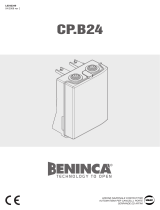
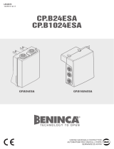
DA.24V
CP.EVA
Libro istruzioni
Operating instructions
Betriebsanleitung
Livret d’instructions
Manual de instrucciones
Książeczka z instrukcjami
UNIONE NAZIONALE COSTRUTTORI
AUTOMATISMI PER CANCELLI, PORTE,
SERRANDE ED AFFINI

2
3
Dichiarazione CE di conformità Déclaration CE de conformité
EC declaration of conrmity Declaracion CE de conformidad
EG-Konformitatserklarung Deklaracja UE o zgodności
Con la presente dichiariamo che il nostro prodotto
We hereby declare that our product
Hiermit erklaren wir, dass unser Produkt
Nous déclarons par la présente que notre produit
Por la presente declaramos que nuestro producto
Niniejszym oświadczamy że nasz produkt
DA.24V
è conforme alle seguenti disposizioni pertinenti:
complies with the following relevant provisions:
folgenden einschlagigen Bestimmungen entspricht:
correspond aux dispositions pertinentes suivantes:
satisface las disposiciones pertinentes siguientes:
zgodny jest z poniżej wyszczególnionymi rozporządzeniami:
Direttiva sulla compatibilità elettromagnetica (89/336/
CCE, 93/68/CEE)
EMC guidelines (89/336/EEC, 93/68/EEC)
EMV-Richtlinie (89/336/EWG, 93/68/EWG)
Directive EMV (89/336/CCE, 93/68/CEE) (Compatibilité
électromagnétique)
Reglamento de compatibilidad electromagnética (89/336/
MCE, 93/68/MCE)
Wytyczna odnośnie zdolności współdziałania elektromagne-
tycznego (89/336/EWG, 93/68/EWG)
Norme armonizzate applicate in particolare:
Applied harmonized standards, in particular:
Angewendete harmonisierte Normen, insbesondere:
Normes harmonisée utilisées, notamment:
Normas armonizadas utilzadas particularmente:
Normy standard najczęściej stosowane:
EN 55014-1, EN 55014-2, EN 61000-3-2, EN 61000-3-3
Benincà Luigi, Responsabile legale.
Sandrigo, 05/04/2008.
Direttiva sulla bassa tensione (73/23/CEE, 93/68/CEE)
Low voltage guidelines (73/23/EEC, 93/68/EEC)
Tiefe Spannung Richtlinie (73/23/EWG, 93/68/EWG)
Directive bas voltage (73/23/CEE, 93/68/CEE)
Reglamento de bajo Voltaje (73/23/MCE, 93/68/MCE)
Wytyczna odnośnie niskiego napięcia (73/23/EWG, 93/
68/EWG)
Norme armonizzate applicate in particolare:
Applied harmonized standards, in particular:
Angewendete harmonisierte Normen, insbesondere:
Normes harmonisée utilisées, notamment:
Normas armonizadas utilzadas particularmente:
Normy standard najczęściej stosowane:
EN 60204-1, EN 60335-1
Automatismi Benincà SpA
Via Capitello, 45
36066 Sandrigo (VI)
ITALIA


4
5
Centrale di comando DA,24V/CP.EVA
Centrale di comando per motori 24Vdc di potenza non superiore a 120W per il controllo di barriere
stradali.
AVVERTENZE GENERALI
a) L’installazione elettrica e la logica di funzionamento devono essere in accordo con le normative vigenti.
b) I conduttori alimentati con tensioni diverse, devono essere sicamente separati, oppure devono essere
adeguatamente isolati con isolamento supplementare di almeno 1 mm.
c) I conduttori devono essere vincolati da un ssaggio supplementare in prossimità dei morsetti.
d) Ricontrollare tutti i collegamenti fatti prima di dare tensione.
e) Controllare che le impostazioni dei Dip-Switch siano quelle volute.
f) Gli ingressi N.C. non utilizzati devono essere ponticellati.
FUNZIONI INGRESSI/USCITE
N° Morsetti Funzione Descrizione
1-2 Alimentazione Ingresso 230Vac 50Hz (1-Neutro/2-Fase)
4-5 Motore 24Vdc Collegamento al motore 24Vdc
6-7 Lampeggiante Collegamento lampeggiante 24Vac 40W max.
8-9 24 Vac
Uscita alimentazione accessori 24Vac/0,5A max.
ATTENZIONE: Nel caso di installazione della scheda caricabatteria
CB.24V, l’uscita (in assenza di alimentazione di rete) presenta una
tensione 24Vdc - polarizzata. Vericare il corretto collegamento
dei dispositivi (8:+24Vdc - 9:-24Vdc).
10-11 Luci barriera Collegamento luci asta barriera 24Vdc (10+/11+) -200mA max
(equivalenti a circa 6 luci).
12 COM Comune per tutti gli ingressi di comando.
13 STOP Ingresso pulsante STOP (contatto N.C.)
14 PHOT Ingresso collegamento dispositivi di sicurezza, contatto N.C.
(ad es. fotocellule)
15 OPEN Ingresso pulsante APRE (contatto N.O.)
16 CLOSE Ingresso pulsante CHIUDE (contatto N.O.)
17 Passo-Passo Ingresso pulsante passo-passo (contatto N.O.)
18 COM Comune necorsa.
19 SWC
Ingresso necorsa CHIUSURA (contatto N.C.).
L’apertura di questo contatto interrompe l’alimentazione al motore
al termine della manovra di chiusura della barriera.
20 SWO-R
Ingresso necorsa rallentamento in apertura (contatto N.C.).
Con l’apertura di questo contatto ha inizio la fase di rallentamento
in apertura della barriera.
21 SWC-R
Ingresso necorsa rallentamento in chiusura (contatto N.C.).
Con l’apertura di questo contatto ha inizio la fase di rallentamento
in chiusura della barriera.
24-25 Antenna
Collegamento antenna scheda radioricevente ad innesto
(24-segnale/25-schermo).
28-29 2°Ch radio Uscita contatto N.O. del secondo canale radio.
VAUX-0-VMOT Secondario Collegamento avvolgimento secondario trasformatore
L1-N1 Primario Collegamento avvolgimento primario trasformatore
J3 Ricevitore Radio Connettore ad innesto per ricevente radio.

4
5
Funzione dei Trimmer
SLOWCL Regola la velocità del motore durante la fase di rallentamento in chiusura.
Il rallentamento inizia con l’intercettazione del necorsa SWC-R e termina con l’intercettazione
del necorsa SWC.
SLOWOP Regola la velocità del motore durante la fase di rallentamento in apertura.
Il rallentamento inizia con l’intercettazione del necorsa SWO-R e termina dopo il tempo
impostato con il Dip-Switch N°8.
AMP Regola la sensibilità del sensore amperometrico di rilevamento ostacolo.
Il sensore è attivo in apertura e in chiusura.
Non è attivo durante la fase di rallentamento in apertura.
In caso rilevamento ostacolo:
In fase di apertura ferma la barriera.
In fase di chiusura ferma e riapre completamente.
TCA Permette di regolare il tempo di chiusura automatica se attivata dal Dip-Switch N°1.
La regolazione varia da un minimo di 1s ad un massimo di 90s
Funzione Dip-Switch
DIP 1 “TCA” Abilita o disabilita la chiusura automatica.
Off: chiusura automatica disabilitata
On: chiusura automatica abilitata
DIP 2 “PRELAM.” Abilita o disabilita il prelampeggio
Off: Prelampeggio disabilitato
On: Prelampeggio abilitato. Il lampeggiante si attiva 3s prima della partenza del
motore.
DIP 3 “SCL” (DIP1 deve essere ON) Abilita o disabilita la funzione chiusura rapida dopo
fotocellula.
Off: Funzione disattivata. Dopo l’intervento della fotocellula, il tempo della chiusura
automatica resta invariato.
On: Funzione Chiusura rapida attivata. Dopo l’intervento della fotocellula, il tempo
della chiusura automatica si riduce a 1 secondo.
DIP 4 “P.P. Mod” Seleziona la modalità di funzionamento del ”Pulsante P.P.” e del trasmettitore.
Off: Funzionamento: APRE > STOP > CHIUDE > STOP >
On: Funzionamento: APRE > CHIUDE > APRE >
DIP 5 “LIGHT” Seleziona la modalità di funzionamento delle luci barriera collegate ai morsetti
10/11.
Off: Lampeggio costante delle luci in fase di apertura e a barriera aperta.
On: Luce accesa ssa a barriera aperta. Da utilizzare come spia barriera aperta o
per collegamento a dispositivi 24Vdc di conteggio veicolare.
DIP 6 “COND.” Abilita o disabilita la funzione condominiale.
Off: Funzione condominiale disabilitata.
On: Funzione condominiale abilitata. L’impulso P.P. o del trasmettitore non ha
effetto durante la fase di apertura e durante la fase TCA (se attivata).
DIP 7 “AMPCL” Abilita o disabilita il sensore amperometrico durante la fase di rallentamento in
chiusura.
Off: Sensore amperometrico abilitato durante la fase di rallentamento in chiusura.
On: Sensore amperometrico disabilitato durante la fase di rallentamento in
chiusura.
DIP 8 “Trall-OP” Seleziona la durata in secondi della fase di rallentamento in apertura.
Selezionare il tempo in base alla velocità dell’asta ed al punto di intervento del
necorsa di rallentamento in apertura
Off: rallentamento di 4s.
On: rallentamento di 2s.
Nel caso si renda necessario è possibile il comando dell’automazione in modalità UOMO PRESENTE
ponendo tutti i DIP in ON.

6
7
Regolazione della velocità barriera
ATTENZIONE! Questa regolazione influisce sul grado di sicurezza dell’automazione.
Verificare che la forza applicata sull’asta sia conforme con quanto previsto dalle normative vigenti.
Ogni modifica della velocità richiede una nuova taratura del sensore amperometrico.
Sul trasformatore di alimentazione è presente un connettore Faston (VMOT) che permette la regolazione
della velocità della barriera dei motori su 3 diversi livelli (18-23-26).
Posizionando il Faston (VMOT) su 18 si ha la velocità minore, spostandolo su 26 si ha la velocità
maggiore.
Nel caso di sia presente l’appoggio mobile VE.AM o la rastrelliera VE.RAST, ridurre la velocità dell’asta.
Diagnostica LED
La centrale dispone di una serie di LED di autodiagnosi che consentono il controllo di tutte le funzioni:
Led POWER Lampeggia a segnalare la presenza di alimetnazione di rete
Led STOP Si spegne con l’attivazione del pulsante STOP
Led PHOT Si spegne con fotocellule non allineate o in presenza di ostacoli
Led OPN Si accende con l’attivazione del pulsante OPEN
Led CLS Si accende con l’attivazione del pulsante CLOSE
Led PP Si accende con l’attivazione del pulsante PP
Led SWC Si accende con l’attivazione del necorsa di chiusura SWC
Led SWO-R Si accende con l’attivazione del necorsa di rallentamento apertura SWO-R
Led SWC-R Si accende con l’attivazione del necorsa di rallentamento chiusura SWC-R

6
7
DA.24V/CP.EVA Control Unit
Control unit for 24Vdc motors with power not exceeding 120W to control road barriers.
GENERAL WARNINGS
a) The wire connections and the operating logic should be in compliance with regulations in force.
b) The cables featuring different voltage should be physically detached, or adequately insulated by an
additional insulation of at least 1 mm.
c) The cables should be further fastened in proximity to the terminals.
d) Check all connections before powering the unit.
e) Check that setting of the Dip-switches are the required ones.
f) The Normally Closed (N.C.) contacts which are not in use should be short-circuited.
INPUT/OUTPUT FUNCTIONS
N° of terminals Function Description
1-2 Power supply Input, 230Vac 50Hz (1-Neutral/2-Phase)
4-5 Motor 24Vdc Connection to motor, 24Vdc
6-7 Flasher Flasher connection, 24Vac 40W max.
8-9 24 Vac
Output, accessories power supply - 24Vac/0.5A max.
IMPORTANT: If the battery charger board CB.24V is installed,
the output (without mains power connected) has a 24Vdc po-
larised voltage. Make sure the devices are correctly connected
(i.e. 8:+24Vdc - 9:-24Vdc).
10-11 Road barrier lights Connection of barrier beam lights, 24Vdc (10+/11+) -200mA
max (equal to approx. 6 lights).
12 COM Common to all control inputs.
13 STOP Input, STOP push-button (N.C. contact)
14 PHOT Input, safety devices connection, N.C. contact
(ex. Photocells)
15 OPEN Input, OPEN push-button (N.O. contact)
16 CLOSE Input, CLOSE push-button (N.O. contact)
17 Step-by-Step Input, step-by-step push-button (N.O. contact)
18 COM Common, limit switches.
19 SWC
Input, CLOSURE limit switch (N.C. contact).
When this contact is opened, power supply to the motor is cut-
off at the end of the road barrier closing operation.
20 SWO-R
Input, braking limit switch in the opening phase (N.C. contact).
When this contact is opened, braking starts during the barrier
opening phase.
21 SWC-R
Input, braking limit switch in the closing phase (N.C. contact).
When this contact is opened, braking starts during the barrier
closing phase.
24-25 Antenna Connection of the antenna radio receiver removable board
(24-signal/25-screen).
28-29 Radio 2nd Ch Output, N.O. contact of the second radio channel.
VAUX-0-VMOT Secondary Connection of the transformer secondary winding
L1-N1 Primary Connection of the transformer primary winding
J3 Radio receiver Removable connector for radio receiver.

8
9
Trimmer functions
SLOWCL The motor speed during braking in the closing phase is adjusted by this trimmer.
Braking starts with the triggering of the SWC-R limit switch and ends when the SWC limit
switch is activated.
SLOWOP The motor speed during braking in the opening phase is adjusted by this trimmer.
Braking starts with the triggering of the SWO-R limit switch and ends when the time preset
with Dip-Switch N°8 has elapsed.
AMP The obstacle detection amperometric sensor sensitivity is adjusted by this trimmer.
The sensor is activated in both opening and closing phases.
It is not activated during braking in the opening phase.
Should an obstacle be detected:
In the opening phase, the road barrier movement is stopped.
In the closing phase, the barrier is stopped and then re-opened completely.
TCA This trimmer allows the adjustment of the automatic closure time if activated by Dip-Switch
No. 1.
The adjustment ranges between 1s minimum and 90s maximum
Dip-Switch functions
DIP 1 “TCA” The automatic closure is enabled or disabled
Off: disabled automatic closure
On: enabled automatic closure
DIP 2 “PRELAM.” Forewarning ashing light is enabled or disabled
Off: disabled forewarning ashing light
On: enabled forewarning ashing light. The ashing light is activated 3s before the
starting of the motor.
DIP 3 “SCL” (DIP 1 must be ON) This enables or disables the rapid closure function after the
photocell activation.
Off: Disabled function. After the activation of the photocell, the automatic closure
time remains unchanged.
On: Enabled rapid closure function. After activation of the photocell, the automatic
closure time is reduced by 1 second.
DIP 4 “P.P. Mod” The operating mode of the “P.P. (Step-by-Step) Push button” and of the
transmitter are selected.
Off: Operation: OPEN > STOP > CLOSE > STOP >
On: Operation : OPEN > CLOSE > OPEN >
DIP 5 “LIGHT” The operating mode of the road barrier lights connected to terminals 10/11 is
selected.
Off: Continuous ashing of lights in the opening phase and with open barrier.
On: Steady light on with open barrier. To be used as open barrier warning light or
for connection to 24Vdc devices for vehicle counting.
DIP 6 “COND.” The multi-at function is enabled or disabled.
Off: disabled multi-at function.
On: enabled multi-at function. The P.P. (Step-by-step) impulse or the impulse
of the transmitter have no effect in the opening phase and during TCA phase (if
activated).
DIP 7 “AMPCL” The amperometric sensor is enabled or disabled during braking in the closing
phase.
Off: Enabled amperometric sensor during braking in the closing phase
On: Disabled amperometric sensor during braking in the closing phase..
DIP 8 “Trall-OP” The duration in seconds of braking in the opening phase is selected.
Select time according to the speed of the road barrier beam and the triggering
point of the braking limit switch in the opening phase
Off: 4s braking
On: 2s braking
If required, the system can be controlled in SERVICE MAN mode by switching all Dip Switched to ON

8
9
To adjust the road barrier speed
WARNING! This adjustment affects the safety level of the automatic system.
Check that the force applied to the road barrier beam complies with regulations in force.
Any change in speed requires a new calibration of the amperometric sensor.
A Faston (VMOT) connector is provided on the power supply transformer. This allows for the adjustment of
the road barrier motor speed at three different levels (18-23-26).
By positioning the Faston (VMOT) to 18 a lesser speed is provided, by moving the Faston to 26 a higher
speed is provided.
Should the VE.AM mobile stand or the VE.RAST rack be present, reduce the beam speed.
Diagnostics of LEDs
The control unit is provided with a series of self-diagnostic LEDs which permit to check all functions:
POWER LED It ashes to indicate the presence of mains power supply
STOP LED It switches off when the STOP button is activated
PHOT LED It switches off when the photocells are not aligned or in the presence of obstacles
OPN LED It switches on when the OPEN button is activated
CLS LED It switches on when the CLOSE button is activated
PP LED It switches on when the PP button is activated
SWC LED It switches on when the SWC closing limit switch is activated
SWO-R LED It switches on when the SWO-R opening braking limit switch is activated
SWC-R LED It switches on when the SWC-R closing braking limit switch is activated

10
11
Steuereinheit DA.24V/CP.EVA
Die Steuereinheit für Motoren zu 24Vdc mit einer Leistung von maximal 120W kann zur Steuerung der
Straßenschranken verwendet werden.
ALLGEMEINE HINWEISE
a) Die elektrische Installation und die Betriebslogik müssen den geltenden Vorschriften entsprechen.
b) Die Leiter die mit unterschiedlichen Spannungen gespeist werden, müssen physisch getrennt oder
sachgerecht mit einer zusätzlichen Isolierung von mindestens 1 mm isoliert werden.
c) Die Leiter müssen in der Nähe der Klemmen zusätzlich befestigt werden.
d) Alle Anschlüsse nochmals prüfen, bevor die Zentrale mit Strom versorgt wird.
e) Kontrollieren, ob die Dip-Schalter richtig positioniert sind.
f) Die nicht verwendeten N.C. Eingänge müssen überbrückt werden.
FUNKTIONEN EINGÄNGE/AUSGÄNGE
Klemme Nr. Funktion Beschreibung
1-2 Speisung Eingang 230Vac 50Hz (1- Nulleiter /2-Phase)
4-5 Motor 24Vdc Anschluss an den Motor 24Vdc
6-7 Blinkleuchte Anschluss Blinkleuchte 24Vac 40W max.
8-9 24 Vac
Ausgang Speisung Zubehör 24Vac/0,5A max.
ACHTUNG: Falls die Karte des Batterieladegeräts CB.24V instal-
liert ist, weist der Ausgang (bei Ausfall der Netzversorgung) eine
polarisierte Spannung von 24Vdc auf. Den korrekten Anschluss
der Vorrichtungen kontrollieren (8:+24Vdc - 9:-24Vdc).
10-11 Schrankenleuchten Anschluss Schrankenleuchten 24Vdc (10+/11+) -200mA max (ent-
spricht ca. 6 Leuchten)
12 COM Allgemein für alle Steuereingänge.
13 STOP Eingang Taste STOP (Kontakt N.C.)
14 PHOT Eingang Anschluss Sicherheitsvorrichtungen, Kontakt N.C.
(z.B. Fotozellen)
15 OPEN Eingang Taste ÖFFNEN (Kontakt N.O.)
16 CLOSE Eingang Taste SCHLIESSEN (Kontakt N.O.)
17 Schritt-Schritt Eingang Taste Schritt-Schritt (Kontakt N.O.)
18 COM Allgemein Endschalter
19 SWC
Eingang Endschalter SCHLIESSEN (Kontakt N.C.).
Wird dieser Kontakt geöffnet, wird die Motorenspeisung am Ende
des Schließvorgangs der Schranke unterbrochen.
20 SWO-R
Eingang Endschalter Geschwindigkeitsabnahme beim Öffnen
(Kontakt N.C.).
Beim Öffnen dieses Kontakts beginnt die Phase der Geschwindig-
keitsabnahme beim Öffnen der Schranke.
21 SWC-R
Eingang Endschalter Geschwindigkeitsabnahme beim Schließen
(Kontakt N.C.).
Beim Schließen dieses Kontakts beginnt die Phase der Geschwin-
digkeitsabnahme beim Schließen der Schranke.
24-25 Antenne Anschluss Antenne der Karte des steckbaren Funkempfängers
(24-Signal/25-Schirm).
28-29 2°Ch radio Ausgang Kontakt N.O. des zweiten Funkkanals.
VAUX-0-VMOT Sekundär Anschluss Wicklung des sekundären Transformators
L1-N1 Primär Anschluss Wicklung des sekundären Transformators
J3 Funkempfänger Steckverbinder für Funkempfänger.

10
11
Trimmer-Funktionen
SLOWCL Regelt die Geschwindigkeit des Motors während der Phase der Geschwindigkeitsabnahme
beim Schließen.
Die Geschwindigkeitsabnahme beginnt bei Erreichen des Endschalters SWC-R und endet bei
Erreichen des Endschalters SWC.
SLOWOP Regelt die Geschwindigkeit des Motors während der Phase der Geschwindigkeitsabnahme
beim Öffnen.
Die Geschwindigkeitsabnahme beginnt bei Erreichen des Endschalters SWO-R und endet
nachdem die durch den Dip-Schalter Nr. 8 eingestellte Zeit abgelaufen ist.
AMP Regelt die Empndlichkeit des Stromsensors, der der Hinderniserkennung dient.
Der Sensor ist beim Öffnen und Schließen aktiv. Während des Öffnungsvorgangs, ist der
Sensor bei der Geschwindigkeitsabnahme nicht aktiv.
Im Falle einer Hinderniserkennung:
Beim Öffnen, hält er die Schranke an.
Beim Schließen, hält er die Schranke an und öffnet sie wieder vollkommen.
TCA Ermöglicht es die Zeit des automatischen Schließvorgangs einzustellen, wenn der Dip-
Schalter Nr. 1 aktiv ist.
Die Zeit kann zwischen 1 sec. und maximal 90 sec. eingestellt werden.
Dip-Schalter-Funktion
DIP 1 “TCA” Aktiviert oder deaktiviert den automatischen Schließvorgang.
Off: automatischer Schließvorgang deaktiviert
On: automatischer Schließvorgang aktiviert
DIP 2 “PRELAM.” Aktiviert oder deaktiviert das Vorblinken.
Off: Vorblinken deaktiviert
On: Vorblinken aktiviert. Das Vorblinken beginnt 3 sec. vor dem Einschalten des
Motors.
DIP 3 “SCL” (DIP1 muss auf ON geschaltet sein) Aktiviert oder deaktiviert die Funktion schneller
Schließvorgang nach Fotozelle.
Off: Funktion deaktiviert. Nach dem Einschalten der Fotozelle, bleibt die Zeit für
den automatischen Schließvorgang unverändert.
On: Funktion schnelles Schließen aktiviert. Nach dem Einschalten der Fotozelle,
wird die Zeit für den automatischen Schließvorgang auf 1 Sekunde reduziert.
DIP 4 “P.P. Mod” Wählt die Betriebsweise der „Taste P.P.“ und des Sendegeräts.
Off: Betrieb: ÖFFNEN > STOP > SCHLIESSEN > STOP >
On: Betrieb: ÖFFNEN > SCHLIESSEN > ÖFFNEN
DIP 5 “LIGHT” Wählt die Betriebsweise der Schrankenleuchten, die an die Klemmen 10/11
geschlossen sind.
Off: Die Leuchten blinken konstant während des Öffnungsvorgangs und bei
offener Schranke.
On: Bei offener Schranke leuchtet die Leuchte fest. Sollte als Meldeleuchte für
die offene Schranke oder zum Anschluss von Vorrichtungen zu 24Vdc, die als
Fahrzeugzähler dienen, verwendet werden.
DIP 6 “COND.” Aktiviert oder deaktiviert die Funktion Wohngemeinschaft.
Off: Funktion Wohngemeinschaft deaktiviert.
On: Funktion Wohngemeinschaft aktiviert. Auf den Öffnungsvorgang und auf die
Phase TCA (wenn aktiv) haben weder der Schritt-Schritt-Impuls noch der Impuls
des Sendegeräts Einuss.
DIP 7 “AMPCL” Aktiviert oder deaktiviert den Stromsensor während der Phase der
Geschwindigkeitsabnahme beim Schließen.
Off: Stromsensor während der Geschwindigkeitsabnahme beim Schließen
aktiviert.
On: Stromsensor während der Geschwindigkeitsabnahme beim Schließen
deaktiviert.

12
13
DIP 8 “Trall-OP” Wählt die Dauer der Geschwindigkeitsabnahme beim Öffnen.
Die Dauer je nach Geschwindigkeit der Schranke und je nach dem wann der
Endschalter der Geschwindigkeitsabnahme beim Öffnen eingeschaltet wird,
wählen.
Off: Dauer der Geschwindigkeitsabnahme 4s.
On: Dauer der Geschwindigkeitsabnahme 2s.
Falls erforderlich, kann die Automationssteuerung im Modus MANN VORHANDEN verwendet werden indem
alle Dip-Schalter auf ON positioniert werden.
Schrankengeschwindigkeit einstellen
ACHTUNG! Diese Einstellung hat Einfluss auf die Sicherheit der Automatik.
Die für die Schranke angewendete Kraft muss den geltenden Vorschriften entsprechen.
Bei jeder Geschwindigkeitsänderung muss der Stromsensor neu geeicht werden.
Der Speisetrafo ist mit einem Faston (VMOT) Verbinder versehen, durch den die Schrankengeschwindigkeit
der Motoren auf 3 verschiedene Stufen eingestellt werden kann (18-23-26).
Wird der Faston Verbinder (VMOT) auf 18 eingestellt, wird die Geschwindigkeit auf das Minimum geregelt;
wird er auf 26 eingestellt, wird die maximale Geschwindigkeit erreicht.
Falls die mobile Auage VE.AM oder das Brett VE.RAST vorhanden sind, die Schrankengeschwindigkeit
verringern.
Diagnostik der LEUCHTEN
Die Zentrale verfügt über eine Reihe von Leuchten zur Selbstdiagnostik über welche alle Funktionen
kontrolliert werden können:
Led POWER Blinkt wenn die Stromversorgung vorhanden ist
Led STOP Schaltet aus, wenn die Taste STOP aktiviert wird
Led PHOT Schaltet aus wenn die Lichtschranken nicht geuchtet sind oder im Falle einer
Hinderniserkennung
Led OPN Schaltet ein, wenn die Taste OPEN aktiviert wird.
Led CLS Schaltet ein, wenn die Taste CLOSE aktiviert wird.
Led PP Schaltet ein, wenn die Taste PP aktiviert wird.
Led SWC Schaltet ein, wenn der Endschalter für den Schließvorgang SWC aktiviert wird.
Led SWO-R Schaltet ein, wenn der Endschalter für die Geschwindigkeitsabnahme beim Öffnen SWO-R
aktiviert wird.
Led SWC-R
Schaltet ein, wenn der Endschalter für die Geschwindigkeitsabnahme beim Schließen SWC-R
aktiviert wird.

12
13
Centrale de commande DA.24V/CP.EVA
Centrale de commande pour moteurs 24Vcc d’une puissance non supérieure à 120W pour le contrôle de
barrières routières.
AVERTISSEMENTS GENERAUX
a) L’installation électrique et la logique de fonctionnement doivent être conformes aux normes en vigueur.
b) Les conducteurs alimentés avec des tensions différentes doivent être séparés physiquement, ou
adéquatement isolés avec une isolation supplémentaire d’au moins 1 mm.
c) Les conducteurs doivent être contraints par une xation supplémentaire à proximité des bornes.
d) Avant de mettre sous tension, contrôler à nouveau toutes les connexions réalisées.
e) Contrôler que les réglages des dip-switches sont ceux désirés.
f) Réaliser un pontet sur les entrées N.F. non utilisées.
FONCTIONS ENTRÉES/SORTIES
N. Bornes Fonction Description
1-2 Alimentation Entrée 230Vca 50Hz (1-Neutre/2-Phase)
4-5 Moteur 24Vdc Connexion au moteur 24Vcc
6-7 Clignotante Connexion clignotante 24Vca 40W max.
8-9 24 Vca
Sortie alimentation accessoires 24Vca/0,5A max.
ATTENTION: En cas d’installation de la carte chargeur de batterie
CB.24V, la sortie (en l’absence d’alimentation de secteur) présente
une tension de 24 Vcc - polarisée. Vérier la connexion correcte
des dispositifs (8:+24 Vcc - 9:-24 Vcc).
10-11 Lumières barrière Connexion lumières tige barrière 24Vcc (10+/11+) -200mA max
(équivalent à 6 lumières environ).
12 COM Commun pour toutes les entrées de commande.
13 STOP Entrée bouton STOP (contact N.F.)
14 PHOT Entrée connexion dispositifs de sécurité, contact N.F
(par ex. photocellules)
15 OPEN Entrée bouton OUVRIR (contact N.O.)
16 CLOSE Entrée bouton FERMER (contact N.O.)
17 Pas à pas Entrée bouton pas à pas (contact N.O.)
18 COM Commun n de course.
19 SWC
Entrée n de course FERMETURE (contact N.F.).
L’ouverture de ce contact coupe l’alimentation du moteur à la n
de la manœuvre de fermeture de la barrière.
20 SWO-R
Entrée n de course ralentissement en ouverture (contact N.F.).
Par l’ouverture de ce contact commence la phase de ralentisse-
ment en ouverture de la barrière.
21 SWC-R
Entrée n de course ralentissement en fermeture (contact N.F.).
Par l’ouverture de ce contact commence la phase de ralentisse-
ment en fermeture de la barrière.
24-25 Antenne Connexion antenne carte récepteur radio enchable.
(24-signal/25-écran).
28-29 2°Ch radio Sortie contact N.O. du second canal radio.
VAUX-0-VMOT Secondaire Connexion enroulement secondaire transformateur.
L1-N1 Primaire Connexion enroulement primaire transformateur
J3 Récepteur Radio Connecteur à enclenchement pour réception radio.

14
15
Fonction des Trimmers
SLOWCL Règle la vitesse du moteur durant le ralentissement en fermeture.
Le ralentissement commence avec le captage du n de course SWC-R et s’achève avec le
captage du n de course SWC.
SLOWOP Règle la vitesse du moteur durant le ralentissement en ouverture.
Le ralentissement commence avec le captage du n de course SWO-R et s’achève après le
temps programmé avec le Dip-Switch N°8.
AMP Règle la sensibilité du capteur ampèremétrique de détection de l’obstacle.
Le capteur est actif en ouverture et en fermeture.
Il n’est pas actif durant le ralentissement en ouverture.
En cas de détection de l’obstacle:
En ouverture il arrête la barrière.
En fermeture il arrête et ouvre complètement.
TCA Permet de régler le temps de fermeture automatique si activée par le Dip-Switch N°1.
Le réglage varie d’un minimum de 1 s à un maximum de 90s
Fonction des Dip-Switches
DIP 1 “TCA” Valide ou invalide la fermeture automatique.
Off: fermeture automatique invalidée
On: fermeture automatique validée
DIP 2 “PRELAM.” Valide ou invalide le clignotement
Off: Clignotement invalidé
On: Clignotement validé. Le clignotement s’active 3s avant le démarrage du
moteur.
DIP 3 “SCL” (DIP1 doit être sur ON) Valide ou invalide la fonction fermeture rapide après la
photocellule.
Off: Fonction invalidée. Après l’intervention de la photocellule, le temps de la
fermeture automatique reste inchangé.
On: Fonction Fermeture rapide validée. Après l’intervention de la photocellule, le
temps de la fermeture automatique se réduit à 1 seconde.
DIP 4 “P.P. Mod” Sélectionne le mode de fonctionnement du ”Bouton P.P.” et de l’émetteur.
Off: Fonctionnement: OUVRIR > STOP > FERMER > STOP >
On: Fonctionnement: OUVRIR > FERMER > OUVRIR >
DIP 5 “LIGHT” Sélectionne le mode de fonctionnement des barrières reliées aux bornes 10/11.
Off: Clignotement constant des lumières en ouverture et lorsque la barrière est
ouverte.
On: Lumière allumée xe lorsque la barrière est ouverte. S’utilise comme voyant
barrière ouverte ou pour la connexion aux dispositifs à 24Vcc du comptage des
véhicules.
DIP 6 “COND.” Valide ou invalide la fonction copropriété.
Off: Fonction copropriété invalidée.
On: Fonction copropriété validée. L’impulsion P.P. ou de l’émetteur n’a pas d’effet
durant l’ouverture et la phase TCA (si activée).
DIP 7 “AMPCL” Valide ou invalide le capteur ampèremétrique durant la phase de ralentissement en
fermeture.
Off: Capteur ampèremétrique validé durant la phase de ralentissement en
fermeture.
On: Capteur ampèremétrique invalidé durant la phase de ralentissement en
fermeture.
DIP 8 “Trall-OP” Sélectionne la durée en secondes du ralentissement en ouverture.
Sélectionne le temps sur la base de la vitesse de la tige et du point d’intervention
du n de course de ralentissement en ouverture
Off: ralentissement de 4s.
On: ralentissement de 2s.

14
15
En cas de nécessité, on peut avoir la commande de l’automation en modalité HOMME MORT en plaçant
tous les DIP sur ON.
Réglage de la vitesse de la barrière
ATTENTION! Ce réglage a une influence sur le degré de sécurité de l’automatisme.
Vérifier que la force appliquée sur la tige est conforme aux normes en vigueur.
Toute modification de la vitesse requiert un nouvel étalonnage du capteur ampèremétrique.
Le transformateur d’alimentation monte un connecteur Faston (VMOT) qui permet le réglage de la vitesse
de la barrière des moteurs sur 3 niveaux différents (18-23-26).
Placer le Faston (VMOT) sur 18 pour obtenir la vitesse inférieure et sur 26 pour obtenir la vitesse
supérieure.
En présence de l’appui mobile VE.AM ou du râtelier VE.RAST, réduire la vitesse de la tige.
Diagnostic LEDS
La centrale dispose d’une série de leds d’autodiagnostic qui consentent le contrôle de toutes les
fonctions :
Led POWER Clignote pour signaler la présence d’alimentation du réseau
Led STOP S’éteint à l’activation du bouton STOP
Led PHOT S’éteint si les photocellules ne sont pas alignées ou en présence d’obstacles
Led OPN S’éclaire à l’activation du bouton OPEN
Led CLS S’éclaire à l’activation du bouton CLOSE
Led PP S’éclaire à l’activation du bouton PP
Led SWC S’éclaire à l’activation du n de course de fermeture SWC
Led SWO-R S’éclaire à l’activation du n de course de ralentissement ouverture SWO-R
Led SWC-R S’éclaire à l’activation du n de course de ralentissement fermeture SWC-R

16
17
Central de control DA.24V/CP.EVA
Central de control para motores 24Vcc con potencia no superior a 120W para el control de barreras
callejeras.
ADVERTENCIAS GENERALES
a) La instalación eléctrica y la lógica de funcionamiento deben cumplir las normas vigentes.
b) Los conductores alimentados con tensiones distintas deben estar físicamente separados, o bien deben
estar adecuadamente aislados con aislamiento suplementario de por lo menos 1 mm.
c) Los conductores deben estar vinculados por una jación suplementaria cerca de los bornes.
d) Comprobar todas las conexiones efectuadas antes de dar la tensión.
e) Comprobar que las conguraciones de los Dip-Switch sean las deseadas.
f) Las entradas N.C. no utilizadas deben estar puenteadas.
FUNCIONES ENTRADAS/SALIDAS
N° Bornes Función Descripción
1-2 Alimentación Entrada 230Vca 50Hz (1-Neutro/2-Fase)
4-5 Motor 24Vcc Conexión con el motor 24Vcc
6-7 Intermitente Conexión intermitente 24Vca 40W máx.
8-9 24 Vca
Salida alimentación accesorios 24Vca/0,5A máx.
ATENCIÓN: De estar instalada la tarjeta carga-baterías CB.24V, la
tensión de la salida (sin alimentación de red) es de 24Vdc - pola-
rizada. Verificar que los dispositivos (8:+24Vdc - 9:-24Vdc) estén
conectados correctamente.
10-11 Luces barrera Conexión luces barra barrera 24Vcc (10+/11+) -200mA máx. (equi-
valentes a aproximadamente 6 luces).
12 COM Común para todas las entradas de control.
13 STOP Entrada botón STOP (contacto N.C.)
14 PHOT Entrada conexión dispositivos de seguridad, contacto N.C.
(por ej. fotocélulas)
15 OPEN Entrada botón ABRE (contacto N.A.)
16 CLOSE Entrada botón CIERRA (contacto N.A.)
17 Paso-Paso Entrada botón Paso-Paso (contacto N.A.)
18 COM Común final de carrera.
19 SWC
Entrada final de carrera CIERRE (contacto N.C.).
La apertura de este contacto corta la alimentación para el motor al
término de la maniobra de cierre de la barrera.
20 SWO-R
Entrada final de carrera ralentización en apertura (contacto N.C.).
Con la apertura de este contacto comienza la fase de ralentización
en apertura de la barrera.
21 SWC-R
Entrada final de carrera ralentización en cierre (contacto N.C.).
Con la apertura de este contacto comienza la fase de ralentización
en cierre de la barrera.
24-25 Antena Conexión antena tarjeta radio-receptora de enchufe
(24-señal/25-pantalla).
28-29 2°Ch radio Salida contacto N.A. del segundo canal radio.
VAUX-0-VMOT Secundario Conexión bobinado secundario transformador
L1-N1 Primario Conexión bobinado primario transformador
J3 Receptor Radio Conector enchufable para receptora radio.

16
17
Función de los Trimmer
SLOWCL Ajusta la velocidad del motor durante la fase de ralentización en cierre.
La ralentización comienza con la interceptación del nal de carrera SWC-R y termina con la
interceptación del nal de carrera SWC.
SLOWOP Ajusta la velocidad del motor durante la fase de ralentización en apertura.
La ralentización comienza con la interceptación del nal de carrera SWO-R y termina después
del tiempo programado con el Dip-Switch N°8.
AMP Ajusta la sensibilidad del sensor amperimétrico de detección obstáculo.
El sensor está activo en apertura y en cierre.
No está activo durante la fase de ralentización en apertura.
En caso de detección de obstáculo:
En fase de apertura detiene la barrera.
En fase de cierre detiene y abre de nuevo completamente.
TCA Permite ajustar el tiempo de cierre automático si activado por el Dip-Switch N°1.
La regulación varía entre un mínimo de 1s y un máximo de 90s
Función Dip-Switch
DIP 1 “TCA” Habilita o inhabilita el cierre automático.
Off: cierre automático inhabilitado
On: cierre automático habilitado
DIP 2 “PRELAM.” Habilita o inhabilita la intermitencia previa.
Off: Intermitencia previa inhabilitada
On: Intermitencia previa habilitada. El intermitente se activa 3s antes del arranque
del motor.
DIP 3 “SCL” (DIP1 debe estar en ON) Habilita o inhabilita la función de cierre rápido después de
fotocélula.
Off: Función desactivada. Después de la actuación de la fotocélula, el tiempo del
cierre automático no cambia.
On: Función Cierre rápido activada. Después de la actuación de la fotocélula, el
tiempo del cierre automático se reduce a 1 segundo.
DIP 4 “P.P. Mod” Selecciona la modalidad de funcionamiento del ”Botón P.P.” y del transmisor.
Off: Funcionamiento: ABRE > STOP > CIERRA > STOP >
On: Funcionamiento: ABRE > CIERRA > ABRE >
DIP 5 “LIGHT” Selecciona la modalidad de funcionamiento de las luces de la barrera conectadas
con los bornes 10/11.
Off: Parpadeo constante de las luces en fase de apertura y con la barrera abierta.
On: Luz encendida ja con la barrera abierta. A utilizar como chivato de barrera
abierta o para la conexión con dispositivos 24Vcc de conteo de vehículos.
DIP 6 “COND.” Habilita o inhabilita la función comunidad.
Off: Función comunidad inhabilitada.
On: Función comunidad habilitada. El impulso P.P. o del transmisor no tiene
efecto durante la fase de apertura y durante la fase TCA (si activada).
DIP 7 “AMPCL” Habilita o inhabilita el sensor amperimétrico durante la fase de ralentización en
cierre.
Off: Sensor amperimétrico habilitado durante la fase de ralentización en cierre.
On: Sensor amperimétrico inhabilitado durante la fase de ralentización en cierre.
DIP 8 “Trall-OP” Selecciona la duración en segundos de la fase de ralentización en apertura.
Seleccionar el tiempo según la velocidad de la barra y el punto de actuación del
nal de carrera de ralentización en apertura
Off: ralentización de 4s.
On: ralentización de 2s.
Si fuese necesario, es posible controlar la automatización en la modalidad HOMBRE PRESENTE poniendo
todos los DIP en ON.

18
19
Regulación de la velocidad de la barrera
¡ATENCIÓN! Esta regulación repercute en el grado de seguridad de la automatización.
Comprobar que la fuerza aplicada sobre la barra sea conforme con cuanto previsto por las normas
vigentes.
Cualquier modificación de la velocidad requiere una nueva calibración del sensor amperimétrico.
En el transformador de alimentación hay presente un conector Faston (VMOT) que permite la regulación de
la velocidad de la barrera en 3 niveles distintos (18 – 23 – 26).
Poniendo el Faston (VMOT) en 18 se tiene la velocidad más lenta, desplazándolo en 26 se tiene la mayor
velocidad.
Si hay presente el apoyo móvil VE.AM o las franjas VE.RAST, reducir la velocidad de la barra.
Diagnóstico por LEDs
La central tiene una serie de LEDs de autodiagnosis que permiten controlar todas las funciones:
LED POWER Parpadea para señalar la presencia de la alimentación de red
LED STOP Se apaga con la activación del botón STOP
LED PHOT Se apaga con fotocélulas no alineadas o ante obstáculos
LED OPN Se enciende con la activación del botón OPEN
LED CLS Se enciende con la activación del botón CLOSE
LED PP Se enciende con la activación del botón PP
LED SWC Se enciende con la activación del nal de carrera de cierre SWC
LED SWO-R Se enciende con la activación del nal de ralentización apertura SWO-R
LED SWC-R Se enciende con la activación del nal de ralentización cierre SWC-R

18
19
Centralka sterowania DA.24V/CP.EVA
Centralka sterowania zapory drogowej wyposażonej w silniki 24Vdc o mocy nie większej niż 120 W.
OSTRZEŻENIA OGÓLNE
a) Instalacja elektryczna i algorytmy funkcjonowania muszą być zgodne z obowiązującymi normami.
b) Przewody zasilane różnego rodzaju napięciem muszą być oddzielone od siebie, względnie odpowiednio
izolowane z zastosowaniem dodatkowej, co najmniej 1 mm izolacji.
c) W pobliżu zacisków przewody muszą być zamocowane dodatkowym umocowaniem.
d) Przed podaniem napięcia należy sprawdzić prawidłowość wszystkich połączeń.
e) Sprawdzić czy wszystkie ustawienia dip- switchów są takie, jak zamierzono.
f) Wejścia N.C. nie używane muszą być zmostkowane.
FUNKCJE WEJŚĆ/WYJŚĆ
Nr Zacisku Funkcja Opis
1-2 Zasilanie Wejście 230Vac 50Hz (1-Zerowy/2-Faza)
4-5 Silnik 24Vdc Połączenie silnika 24Vdc
6-7 Lampa migająca Połączenie lampy migającej 24Vac 40W maks.
8-9 24 Vac
Wyjście zasilania akcesoriów 24Vac/0,5A maks.
UWAGA: W przypadku instalacji karty przekaźnika prądu baterii
CB.24V, wyjście (bez napięcia sieciowego) wykazuje napięcie
24Vdc - spolaryzowane.
Sprawdzić podłączenie przyrządów (8:+24Vdc - 9:-24Vdc).
10-11 Światła zapory Połączenie świateł ramienia zapory 24Vdc (10+/11+) -200mA
maks. (odpowiada około 6 punktom świetlnym).
12 Wspólny Wspólny dla wszystkich wejść sterowani.
13 STOP Wejście przycisku STOP (zestyk N.C. normalnie zwarty)
14 FOTOKOM.
Wejście połączenia urządzeń bezpieczeństwa, zestyk N.C.
normalnie zwarty
(na przykład fotokomórki)
15 OPEN Wejście przycisku OTWIERA (zestyk N.O. normalnie otwarty)
16 CLOSE Wejście przycisku ZAMYKA (zestyk N.O. normalnie otwarty)
17 Posuw-posuw Wejście przycisku Posuw-posuw (zestyk N.O. normalnie
otwarty)
18 Wspólny Wspólny ograniczników biegu.
19 SWC
Wejście ogranicznika biegu ZAMYKANIA (zestyk N.C. normalnie
zwarty).
Otwarcie tego zestyku odcina zasilanie silnika po zakończeniu
operacji zamykania zapory.
20 SWO-R
Wejście ogranicznika biegu zwalniania biegu otwierania
(zestyk N.C. normalnie zwarty).
Jednocześnie z otwarciem tego zestyku rozpoczyna się faza
zwalniania biegu przy otwieraniu zapory.
21 SWC-R
Wejście ogranicznika biegu zwalniania biegu zamykania
(zestyk N.C. normalnie zwarty).
Jednocześnie z otwarciem tego zestyku rozpoczyna się faza
zwalniania biegu przy otwieraniu zapory.
24-25 Antena Połączenie złącza anteny karty radioodbiornika
(24-sygnał/25-ekranowanie).
28-29 2°Ch radio Wyjście zestyku N.O. (normalnie otwarty) drugiego kanału radio.
VAUX-0-VMOT Wtórne Połączenie wtórnego uzwojenia trasformatora.
L1-N1 Pierwotne Połączenie pierwotnego uzwojenia trasformatora.
J3 Radioodbiornik Złącze radioodbiornika

20
21
Funkcje trymerów
SLOWCL Reguluje prędkość silnika podczas fazy zwalniania biegu przy zamykaniu.
Zwalnianie biegu rozpoczyna się po przechwyceniu sygnału ogranicznika biegu SWC-R i
kończy po przechwyceniu sygnału ogranicznika biegu SW.
SLOWOP Reguluje prędkość silnika podczas fazy zwalniania biegu przy otwieraniu.
Zwalnianie biegu rozpoczyna się po przechwyceniu sygnału ogranicznika biegu SWO-R i
kończy po upływie określonego czasu ustawionego dip-switchem Nr 8.
AMP Reguluje czułość czujnika amperometrycznego odczytującego przeszkodę.
Czujnik jest aktywny zarówno w fazie otwierania jak i zamykania.
Nie jest aktywny podczas fazy zwalniania biegu przy otwieraniu.
W przypadku odczytania przeszkody:
w fazie otwierania, zatrzymuje zaporę.
w fazie automatycznego zamykania zatrzymuje i otwiera całkowicie.
TCA Pozwala na regulację czasu automatycznego zamykania, jeżyli aktywowana jest przez dip-
switch Nr.1. Regulacji można dokonań w przedziale od min. 1 sek. do maks. 90 sek.
Funkcje Dip-Switchów
DIP 1 “TCA” Włącza lub wyłącza automatyczne zamykanie.
Off: automatyczne zamykanie wyłączone
On: automatyczne zamykanie włączone
DIP 2 “PRELAM.” Włącza lub wyłącza automatyczne ostrzegawcze migotanie lampy
Off: Migotanie ostrzegawcze wyłączone
On: Migotanie ostrzegawcze włączone. Lampa migocząca zaświeca się 3 sek.
przed rozpoczęciem pracy silnika.
DIP 3 “SCL” (DIP1 musi być w pozycji ON) Kwalikuje lub dyskwalikuje funkcję szybkiego
zamykania po zadziałaniu fotokomórki.
Off: Funkcja wyłączona. Czas automatycznego zamykania po zadziałaniu
fotokomórki pozostaje niezmieniony.
On: Funkcja szybkiego zamykania włączona. Po zadziałaniu fotokomórki czas
automatycznego zamykania zmniejsza się o 1 sekundę.
DIP 4 “P.P. Mod” Wybiera tryb działania przycisku P.P. oraz nadajnika.
Off: Działanie: OTWIERA > STOP > ZAMYKA > STOP >
On: Działanie: OTWIERA > ZAMYKA > OTWIERA >
DIP 5 “LIGHT” Wybiera tryb działania oświetlenia zapory, podłączonego do zacisków 10/11.
Off: Stałe migotanie świateł w fazie otwierania i przy zaporze otwartej
On: Świeci się światłem stałym przy zaporze otwartej. Funkcji tej należy używać
jako wskaźnika otwartej zapory lub w celu połączenia z urządzeniem 24Vdc
służącemu do liczenia przejeżdżających pojazdów.
DIP 6 “COND.” Włącza lub wyłącza funkcję użytkownika.
Off: Funkcja użytkownika wyłączona.
On: Funkcja użytkownika włączona. Impuls przycisku P.P. lub nadajnika nie daje
żadnego efektu podczas fazy otwierania lub podczas fazy TCA ( o ile aktywna).
DIP 7 “AMPCL” Włącza lub wyłącza czujnik amperometryczny podczas fazy zwalniania biegu przy
zamykaniu.
Off: Czujnik amperometryczny włączony podczas fazy zwalniania biegu przy
zamykaniu.
On: Czujnik amperometryczny wyłączony podczas fazy zwalniania biegu przy
zamykaniu.
DIP 8 “Trall-OP” Wybiera czas trwania zwolnienia biegu w fazie otwierania.
Ustalić czas w zależności od prędkości poruszania się ramienia oraz momentu
zadziałania ogranicznika biegu fazy zwalniania biegu przy otwieraniu.
Off: zwolnienie 4 sek.
On: zwolnienie 2 sek.
/