Elation PROTEUS RAYZOR 760 WMG Manuale utente
- Categoria
- Stroboscopi
- Tipo
- Manuale utente
Questo manuale è adatto anche per

user manual

2
©2020 ELATION PROFESSIONAL all rights reserved. Information, specifications, diagrams,
images, and instructions herein are subject to change without notice. ELATION
PROFESSIONAL logo and identifying product names and numbers herein are trademarks of
ELATION PROFESSIONAL. Copyright protection claimed includes all forms and matters of
copyrightable materials and information now allowed by statutory or judicial law or
hereinafter granted. Product names used in this document may be trademarks or
registered trademarks of their respective companies and are hereby acknowledged. All
non-ELATION brands and product names are trademarks or registered trademarks of their
respective companies.
ELATION PROFESSIONAL and all affiliated companies hereby disclaim any and all liabilities
for property, equipment, building, and electrical damages, injuries to any persons, and direct
or indirect economic loss associated with the use or reliance of any information contained
within this document, and/or as a result of the improper, unsafe, insufficient and negligent
assembly, installation, rigging, and operation of this product.
Elation Professional USA | 6122 S. Eastern Ave. | Los Angeles, CA. 90040
Elation Professional B.V. | Junostraat 2 | 6468 EW Kerkrade, The Netherlands
+31 45 546 85 66 | +31 45 546 85 96 fax | www.elationlighting.eu | [email protected]
Elation Professional Mexico | AV Santa Ana 30 | Parque Industrial Lerma, Lerma, Mexico 52000
+52 (728) 282-7070
DOCUMENT VERSION
Due to additional product features and/or enhancements,
an updated version of this document may be available
online. Please scan the QR Code with your mobile device or
visit www.elationlighting.com for the latest revision/update of
this manual, before installation and/or programming.
Date
Document
Version
Software
Version ≥
DMX
Channel Modes
Notes
05/28/19
1.0
1.2.1
25 / 52 / 80
Initial release.
09/30/19
1.1
N/C
NO CHANGE
Included RJ4 data cable note.
10/15/19
2.0
1.2.2
NO CHANGE
Updated System Sub Menus, DMX Control
Channel, and RGBW/SparkLED FX Tables.
08/10/20
2.1
N/C
NO CHANGE
Updated thermal
10/14/20
2.2
N/C
NO CHANGE
Updated specifications

3
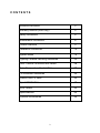
CONTENTS
General Information
4
Warranty Returns (USA Only)
5
Safety Guidelines
6
Maintenance Guidelines
8
Fixture Overview
9
Installation Guidelines
10
System Menu
15
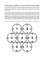
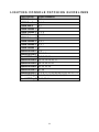
Lighting Console Patching Guidelines
23
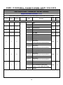
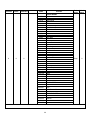
DMX Channel Functions and Values
28
Color Temperature Control Table
39
FX Generator Guidelines
40
RGBW Pixel FX Table
42
SparkLED FX Table
47
Error Codes
52
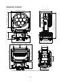
Specifications
53
Optional Accessories
55

4
GENERAL INFORMATION
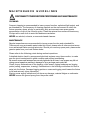
INTRODUCTION
Please read and understand the instructions in this manual carefully and thoroughly before
attempting to operate this device. These instructions contain important safety and use
information.
IP65 RATED
An IP rated lighting fixture is one, which is commonly installed in outdoor environments and
has been designed with an enclosure that effectively protects the ingress (entry) of external
foreign objects such as dust and water. The International Protection (IP) rating system is
commonly expressed as "IP" (Ingress Protection) followed by two numbers (i.e. IP65) where
the numbers define the degree of protection. The first digit (Foreign Bodies Protection)
indicates the extent of protection against particles entering the fixture and the second digit
(Water Protection) indicates the extent of protection against water entering the fixture. An
IP65 rated lighting fixture is one, which has been designed and tested to protect against the
ingress of dust (6) and low-pressure water jets from any direction (5).
UNPACKING
Every device has been thoroughly tested and has been shipped in perfect operating
condition. Carefully check the shipping carton for damage that may have occurred during
shipping. If the carton is damaged, carefully inspect the device for damage, and be sure all
accessories necessary to install and operate the device have arrived intact. In the event
damage has been found or parts are missing, please contact our customer support team for
further instructions. Please do not return this device to your dealer without first contacting
customer support. Please do not discard the shipping carton in the trash. Please recycle
whenever possible.
BOX CONTENTS
Omega Brackets (x2)
IP65 Rated 5pin DMX Cable
IP65 Rated RJ45 DATA Cable (Fixture to Fixture Interconnect Use Only!)
Power Cable
CUSTOMER SUPPORT
Contact ELATION Service for any product related service and support needs.
Also visit forums.elationlighting.com with questions, comments or suggestions.
ELATION SERVICE USA - Monday - Friday 8:00am to 4:30pm PST
323-582-3322 | Fax 323-832-9142 | [email protected]
ELATION SERVICE EUROPE - Monday - Friday 08:30 to 17:00 CET
+31 45 546 85 63 | Fax +31 45 546 85 96 | [email protected]
REPLACEMENT PARTS please visit parts.elationlighting.com

5
WARRANTY RETURNS (USA ONLY)
To obta in warrant y service, a R etur n Materials Authoriz ation (RMA ) number must first be
obtained from ELATION. It is the Customer’s responsibility to provide product proof of purchase
and serial number by acceptable evidence such as an invoice copy or an approved ELATION
Extended Warranty Certificate (“EWC”) and any relevant maintenance records at the time
warranty service is sought. Failure to provide acceptable evidence of product proof of purchase
or EWC and any relevant maintenance records may be cause for denial of warranty service.
Products returned for warranty service must be sent without any accessories (i.e., power, data,
and safety cables, brackets, clamps, rigging hardware, frost filters, gel frames, barn doors, lens,
hoses, nozzles, rack mounting hardware, etc.), must be boxed using the original and/or suitable
packaging materials (double-box and foam) that provides ample product protection for ground
and/or air freight transit, and must be shipped freight pre-paid and insured to ELATION in Los
Angeles, CA or an ELATION Authorized Service Center. The RMA number must be clearly
written on the outside of the return box, and a brief description of the problem and the RMA
number must be documented and included in the box.
Products returned for warranty service without an RMA number clearly marked on the outside
of the package will be refused and returned to the shipper at the Customer’s expense. Products
returned for warranty service, which are received damaged due to inadequate and/or improper
packaging and/or due to damage caused by shipping carrier, may incur additional repair
charges before warranty service begins and/or may void this warranty. If any product
accessories (included and/or optional) are shipped with the product, ELATION and/or the
ELATION Authorized Service Center shall have no liability what so ever for the loss and/or
damage to any such accessories, nor the safe return thereof. If the requested warranty repairs
or service (including parts replacement) are within the terms of this warranty, ELATION will pay
return ground transportation shipping charges to a single designated point within the United
States.

6
SAFETY GUIDELINES
This fixture is a sophisticated piece of electronic equipment. To guarantee a smooth
operation, it is important to follow all instructions and guidelines in this manual. Elation
Professional is not responsible for injury and/or damages resulting from the misuse of this
fixture due to the disregard of the information printed in this manual. Only qualified and/or
certified personnel should perform installation of this fixture and only the original rigging
parts (omega brackets) included with this fixture should be used for installation. Any
modifications to the fixture and/or the included mounting hardware will void the original
manufactures warranty and increase the risk of damage and/or personal injury.
M
PROTECTION CLASS 1 - FIXTURE MUST BE PROPERLY GROUNDED
THERE ARE NO USER SERVICEABLE PARTS INSIDE THIS UNIT.
DO NOT ATTEMPT ANY REPAIRS YOURSELF; DOING SO WILL VOID
YOUR MANUFACTURES WARRANTY. DAMAGES RESULTING FROM
MODIFICATIONS TO THIS FIXTURE AND/OR THE DISREGARD OF
SAFETY INSTRUCTIONS AND GUIDELINES IN THIS MANUAL VOID
THE MANUFACTURES WARRANTY AND ARE NOT SUBJECT TO ANY
WARRANTY CLAIMS AND/OR REPAIRS.
DO NOT PLUG FIXTURE INTO A DIMMER PACK!
NEVER OPEN THIS FIXTURE WHILE IN USE!
UNPLUG POWER BEFORE SERVICING FIXTURE!
NEVER TOUCH FIXTURE DURING OPERATION, AS IT MAY BE HOT!
KEEP FLAMMABLE MATERIALS AWAY FROM FIXTURE!
NEVER LOOK DIRECTLY INTO THE LIGHT SOURCE!
RETINA INJURY RISK - MAY INDUCE BLINDNESS!
SENSITIVE PERSONS MAY SUFFER AN EPILEPTIC SHOCK!
ENSURE ALL CONNECTIONS AND END CAPS ARE PROPERLY
SEALED WITH A DIELECTRIC GREASE (AVAILABLE AT MOST
ELECTRICAL SUPPLIERS) TO PREVENT WATER CORROSION AND/OR
ELECTRICAL SHORT CIRCUIT.
MINIMUM DISTANCE TO OBJECTS/SURFACES
MUST BE 3.3 FEET (1 METER)
MAXIMUM TEMP OF EXTERNAL SURFACE 185° F (85°C)
MINIMUM DISTANCE OF INFLAMMABLE MATERIALS
FROM THE SURFACE 1.6 FEET (0.5 METER)

7
SAFETY GUIDELINES
DO NOT TOUCH the fixture housing during operation. Turn OFF the power and allow
approximately 15 minutes for the fixture to cool down before serving.
DO NOT shake fixture, avoid brute force when installing and/or operating fixture.
DO NOT operate fixture if the power cord is frayed, crimped, damaged and/or if any of the
power cord connectors are damaged and do not insert into the fixture securely with ease.
NEVER force a power cord connector into the fixture. If the power cord or any of its
connectors are damaged, replace it immediately with a new one of similar power rating.
DO NOT block any air ventilation slots.
All fan and air inlets must remain clean and never blocked.
Allow approx. 6” (15cm) between fixture and other devices or a wall for proper cooling.
Always disconnect fixture from main power source before performing any type of service
and/or cleaning procedure. Only handle the power cord by the plug end, never pull out the
plug by tugging the wire portion of the cord.
During the initial operation of this fixture, a light smoke or smell may emit from the interior of
the fixture. This is a normal process and is caused by excess paint in the interior of the casing
burning off from the heat associated with the lamp and will decrease gradually over time.
Consistent operational breaks will ensure fixture will function properly for many years.
ONLY use the original packaging and materials to transport the fixture in for service.

8
MAINTENANCE GUIDELINES
DISCONNECT POWER BEFORE PERFORMING ANY MAINTENANCE!
CLEANING
Frequent cleaning is recommended to insure proper function, optimized light output, and
an extended life. The frequency of cleaning depends on the environment in which the
fixture operates: damp, smoky or particularly dirty environments can cause greater
accumulation of dirt on the fixture’s optics. Clean the external lens surface at least every
20 days with a soft cloth to avoid dirt/debris accumulation.
NEVER use alcohol, solvents, or ammonia-based cleaners.
MAINTENANCE
Regular inspections are recommended to insure proper function and extended life.
There are no user serviceable parts inside this fixture, please refer all other service issues
to an authorized Elation service technician. Should you need any spare parts, please order
genuine parts from your local Elation dealer.
Please refer to the following points during routine inspections:
A detailed electric check by an approved electrical engineer every three months, to make
sure the circuit contacts are in good condition and prevent overheating.
Be sure all screws and fasteners are securely tightened at all times. Lose screws may fall out
during normal operation resulting in damage or injury as larger parts could fall.
Check for any deformations on the housing, color lenses, rigging hardware and rigging
points (ceiling, suspension, trussing). Deformations in the housing could allow for dust to
enter into the fixture. Damaged rigging points or unsecured rigging could cause the fixture
to fall and seriously injure a person(s).
Electric power supply cables must not show any damage, material fatigue or sediments.
NEVER remove the ground prong from the power cable.

9
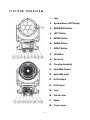
FIXTURE OVERVIEW
1. Lens
2. System Menu LCD Display
3. MODE/ESC Button
4. LEFT Button
5. ENTER Button
6. DOWN Button
7. RIGHT Button
8. UP Button
9. Pan Lock
10. Carrying Handle(s)
11. 5pin DMX Output
12. 5pin DMX Input
13. RJ45 Output
14. RJ45 Input
15. Fuse
16. Service Port
17. Value
18. Power Input

10
INSTALLATION GUIDELINES
FLAMMABLE MATERIAL WARNING
Keep fixture minimum 5.0 feet (1.5m) away from flammable materials and/or pyrotechnics.
ELECTRICAL CONNECTIONS
A qualified electrician should be used for all electrical connections and/or installations.
USE CAUTION WHEN POWER LINKING OTHER MODEL FIXTURES AS THE
POWER CONSUMPTION OF OTHER MODEL FIXTURES MAY EXCEED THE MAX
POWER OUTPUT ON THIS FIXTURE. CHECK SILK SCREEN FOR AMX AMPS.
MINIMUM DISTANCE TO OBJECTS/SURFACES
MUST BE 3.3 FEET (1 METER)
MINIMUM DISTANCE OF INFLAMMABLE MATERIALS
FROM THE SURFACE 1.6 FEET (0.5 METER)
MAXIMUM TEMPERATURE OF EXTERNAL SURFACE 185° F (85°C)
DO NOT INSTALL THE FIXTURE IF YOU ARE NOT QUALIFIED TO DO SO!
Fixture MUST be installed following all local, national, and country commercial electrical and
construction codes and regulations.
Before rigging/mounting a single fixture or multiple fixtures to any metal truss/structure or
placing the fixture(s) on any surface, a professional equipment installer MUST be consulted
to determine if the metal truss/structure or surface is properly certified to safely hold the
combined weight of the fixture(s), clamps, cables, and accessories.
Overhead rigging requires extensive experience, including amongst others calculating
working load limits, installation material being used, and periodic safety inspection of all
installation material and the fixture. If you lack these qualifications, do not attempt the
installation yourself. Improper installation can result in bodily injury.
Fixture ambient operating temperature range is 14° to 113°F. (-10° to 45°C)
Do not use the fixture under or above this temperature.
Fixture(s) should be installed in areas outside walking paths, seating areas, or away from
areas were unauthorized personnel might reach the fixture by hand.
NEVER stand directly below the fixture(s) when rigging, removing or servicing.
Overhead fixture installation must always be secured with a secondary safety attachment,
such as an appropriately rated safety cable.
Allow approximately 15 minutes for the fixture to cool down before serving.

11
INSTALLATION GUIDELINES
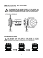
OMEGA BRACKETS INSTALLATION
Insert the Omega Brackets into the matching holes on the bottom of the fixture. Secure the
Omega Brackets to the fixture by turning each quick-lock fastener ¼ turn clockwise; making
sure the fastener is completely locked. Omega Brackets can be installed into the fixture base
as illustrated below.
CLAMP INSTALLATION
When mounting fixture to truss, be sure to secure an appropriately rated professional grade
rigging clamp to the included Omega Brackets using an M10 screw fitted through the
center hole of the Omega Brackets. The fixture provides a built-in rigging points for a
SAFETY CABLE. Be sure to only use one of the designated rigging points for the safety
cable and never secure a safety cable to a carrying handle.
RIGGING
Overhead rigging requires extensive experience, including amongst others calculating
working load limits, installation material being used, and periodic safety inspection of all
installation material and the fixture. If you lack these qualifications, do not attempt the
installation yourself. Improper installation can result in bodily injury.
ALWAYS ATTACH AN APPROPRIATELY RATED SAFETY CABLE (NOT INCLUDED)
THAT MEETS ALL LOCAL, NATIONAL, AND COUNTRY CODES AND REGULATIONS
WHENEVER INSTALLING FIXTURE IN A SUSPENDED ENVIRONMENT!
ART-NET | sACN CONNECTION
When connecting fixture to a network switch to control multiple devices, a Gigabit
Ethernet Switch that supports IGMP (Internet Group Management Protocol) is
required. Using a Gigabit Ethernet Switch that does not support IGMP can cause erratic
behavior of all connected devices to the switch. Click link below for more information
about IGMP. https://en.wikipedia.org/wiki/Internet_Group_Management_Protocol

12
INSTALLATION GUIDELINES
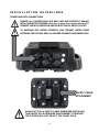
POWER AND DATA CABLES
TO MAINTAIN THE IP65 RATING INTEGRITY OF THE FIXTURE, ALL
CABLES MUST BE RUN TOWARDS THE GROUND TO PREVENT WATER
ACCUMULATION AROUND THE CONNECTIONS. (see illustration below)
SYSTEM MENU LCD DISPLAY
CABLES CABLES
INCLUDED RJ45 DATA CABLE
THE INCLUDED RJ45 DATA CABLE IS FOR FIXTURE TO FIXTURE
INTERCONNECT ONLY! THE RJ45 CABLE CONNECTORS MAY NOT BE
COMPATIBLE WITH OTHER RJ45/ETHERCON TYPE CONNECTORS.

13
INSTALLATION GUIDELINES
POWER AND DATA CONNECTIONS
ENSURE ALL CONNECTIONS AND END CAPS ARE PROPERLY SEALED
WITH A DIELECTRIC GREASE (AVAILABLE AT MOST ELECTRICAL SUPPLIERS) TO
PREVENT WATER CORROSION AND/OR ELECTRICAL SHORT CIRCUIT.
TO MAINTAIN IP65 RATING INTEGRITY AND PREVENT WATER FROM
ENTERING THE FIXTURE, SEAL ALL UNUSED CONNECTION RUBBER CAPS.
ALWAYS ATTACH A SAFETY CABLE WHENEVER INSTALLING
THIS DEVICE IN A SUSPENDED ENVIRONMENT TO ENSURE
THE FIXTURE WILL NOT DROP IF THE CLAMP FAILS.
SAFETY CABLE
ATTACHMENT

14
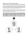
I NSTALLATION GUIDELINES
POTENTIAL INTERNAL FIXTURE DAMAGE FROM EXTERNAL SOURCES OF LIGHT BEAMS
External sources of light beams from direct sunlight, lighting moving head fixtures, and
lasers, which are focused directly towards the exterior housing and/or penetrate the front
lens opening of ELATION lighting fixtures, can cause severe internal damage including
burning to optics, dichroic color filters, glass and metal gobos, prisms, animation wheels,
frost filters, iris, shutters, motors, belts, wiring, discharge lamps, and LEDs.
This issue is not specific only to ELATION lighting fixtures, it is a common issue with lighting
fixtures from all manufacturers. Although there is no true way to fully prevent this issue from
happening, the guidelines below can prevent any potential damage from occurring if
followed. Contact ELATION Service for more details.
DO NOT EXPOSE THE FIXTURE AND/OR FRONT LENS OPENING TO
LIGHT BEAMS FROM DIRECT SUNLIGHT, OTHER LIGHTING MOVING
HEAD FIXTURES, AND LASERS WHILE UNPACKING, INSTALLATION, USE,
AND EXTENDED IDLE TIMES OUTDOORS. DO NOT FOCUS A LIGHT
BEAM FROM ONE LIGHTING FIXTURE DIRECTLY TOWARDS ANOTHER.

15
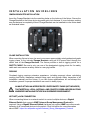
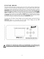
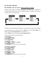
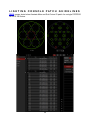
SYSTEM MENU
The fixture includes an easy to navigate system menu. The control panel (see image below)
located on the front of the fixture, provides access to the main system menu and is where
all necessary system adjustments are made to the fixture. During normal operation, pressing
MODE/ESC button once will access the fixture’s main menu. Once in the main menu you
can navigate through the different functions and access the sub-menus with the UP, DOWN,
RIGHT, and LEFT buttons. Once you reach a field that requires adjusting, press the ENTER
button to activate that field and use the UP and DOWN buttons to adjust the field. Pressing
the ENTER button once more will confirm your setting. You may exit the main menu at any
time without making any adjustments by pressing the MODE/ESC button.
To access the LCD Menu Control Display via the internal battery, press and hold the
MODE/ESC button for 10 seconds. The LCD Menu Control Display will shut OFF
automatically about 1 minute from the last button press.
ALTHOUGH E-FLY SETTINGS MAY APPEAR IN THE SYSTEM MENU, THIS FEATURE IS NOT
ACTIVATED. E-FLY WIRELESS DMX IS AN OPTIONAL FEATURE WHICH MUST BE ACTIVATED IN
THE SERVICE MENU. PLEASE CONTACT ELATION SERVICE FOR FURTHER DETAILS.

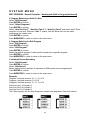
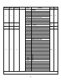
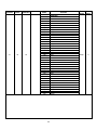
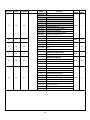
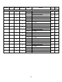
16
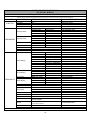
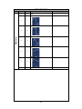
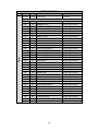
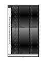
ELATION PROTEUS RAYZOR 760™
S Y S T E M M E N U
Supports Software Versions: ≥ 1.2.1
Features subject to change without notice.
*Rotation direction (Clockwise/Counterclockwise) and control of effects depends on head orientation and Pan/Tilt settings.
MAIN MENU
SUB MENU
OPTIONS / VALUES (Default Settings in BOLD)
DESCRIPTION
FUNCTION
Set Dmx Address
A001~AXXX
DMX Address Setting
Dmx Value
ALL……
DMX Value Display
Slave Mode
Slave1, Slave2, Slave3
Slave Setting
Auto Program
Master / Alone
Auto Program
INFORMATION
Time Information
Current Time
XXXX (Hours)
Fixture Run Time From Power ON
Total R un Ti me
XXXX (Hours)
Fixture Total Run Time
Last Run Time
XXXX (Hours)
Fixture Last Run Time
LastRun Password
Password=038
(PSWD Required)
Clear Last Run
ON / OFF
Clear Fixture Last Run Time
Temp e rature Info
LED Temperature
XXX C° / F °
Temp e rature in LEDs
Head Temperature
XXX C° / F °
Temp e rature in Fi xture Hea d
Base Temperature
XXX C° / F °
Temp e rature in Fi xture Bas e
Humidity Info
Head Humidity
XX%
Humidity in Head
Base Humidity
XX%
Humidity In Base
Ethernet IP
000.000.000.000
000.000.000.000
Displays Fixture Ethernet Address
Fan Info
HeadFan1-6, BaseFan1 / 2 (Standby, Fault)
RPM Speeds of Head/Base Fans
Software Version
1U01: - 7U01:
≥V1.2.1
Software Version
Error Info
Error Record 1 ~ Error Record 10
Fixture Last 10 Error Codes
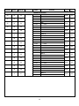
PERSONALITY
Status Settings
Address via DMX
ON/OFF
Address Via DMX
No DMX Status
Close / Hold / Auto
Fixture State When NO DMX Signal
Pan Reverse
ON/OFF
Pan Reverse Movement
Tilt Reverse
ON/OFF
Tilt Reverse Movement
Pan Degree
360/540
Pan Degree Select
Tilt Degree
360/270
Tilt Degree Select
Pan Tilt Path
ShortestPath / ContinuePath
Pan Tilt Path Mode
Feedback
ON/OFF
Movement Feedback
LED Degree Change
0 / 180
LED Degree Change
Hibernation
OFF, 01M~99M, 15M
Stand By Mode
Service Setting
Password
Password=050
Service Password
RDM UID
22A6xxxxxxxx
RDM PID Code (PSWD Required)
Clear Err. Info
ON/OFF
Clear Error Info (PSWD Required)
USB Update
YES/NO
Service Port - Software Updates
Fans Control
Auto, High, Silent
Select Fan Speeds
Display Setting
Shutoff Time
02~60m 05m
Display Shut Off Time
Display Reverse
ON/OFF
Display Reverse 180º
Key Lock
ON/OFF
Key Lock
Temp e rature C/F
Celsius/Fahrenheit
Temp e rature Swi t ch Be tween C˚/ F˚
Initial Status
Control = XXX
Initial Effect Position
Select Signal
DMX Only
DMX In/Out
Art-Net
Select Art-Net
sACN
Activate sACN
Ethernet IP
XXX . XXX . XXX . XXX
Ethernet IP (PSWD Required)
Ether Mask IP
XXX . XXX . XXX . XXX
Ethernet Mask IP (PSWD Required)
Set Universe
000 - 32767
Set ArtNet Universe
Dimmer Mode
Standard, Stage, TV, Architectural,
Theatre, Stage2
Set Dimmer Mode
Refresh
1200, 900-1500, 2500, 4000, 5000, 6,000, 10000,
15000, 20000, 25000 (Hz)
Set LED Refresh Rate
Dimmer Curve
Linear, Square, Inverse Square, S-Curve
Set Dimmer Curve Mode
Reset Default
ON/OFF
Password=011
Restore Factory Settings (PSWD Required)

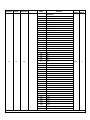
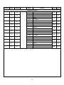
17
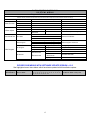
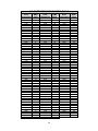
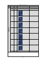
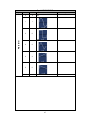
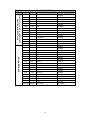
ELATION PROTEUS RAYZOR 760™
S Y S T E M M E N U
Supports Software Versions: ≥ 1.2.1
Features subject to change without notice.
*Rotation direction (Clockwise/Counterclockwise) and control of effects depends on head orientation and Pan/Tilt settings.
MAIN MENU
SUB MENU
OPTIONS / VALUES (Default Settings in BOLD)
DESCRIPTION
Reset Function
Reset All
Reset All Motors
Reset Pan&Tilt
Reset Pan/Tilt
Reset Others
Reset Other Motors
Effect Adjust
Test Channe l
PAN ……
Test fu nction
Manual Control
PAN =XXX, ......
Fine Adjustments
Calibration
Calibration
Password
Password 050 (PSWD Required)
User Mode Set
User Mode
Standard
DMX Channel Modes
Pixels
Extended
Edit Program
Select Program
Auto Pro Part1 = Program 1~10 (Program 1)
Select Programs To Be Run
Auto Pro Part2 = Program 1~10 (Program 2)
Auto Pro Part3 = Program 1~10 (Program 3)
Edit Program
Program 1
Program Test
Testi ng Pro gram
:
Step 01=SCxxx
Program In Loop
Program 10
Step 64=SCxxx
Save and Exit
Edit Scenes
Edit Scene 001
~
Edit Scene 250
Pan,Tilt,……
Save and Automatically Return
--Fade Time--
--Scene Time--
Manual Scenes Edit
Input By Outside
Stores Scenes via Ext DMX Console
Rec. Controller
XX~XX
Automatic Scenes Recorder
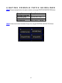
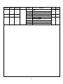
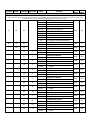
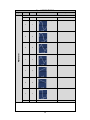
REVISED SUB MENUS WITH SOFTWARE UPDATE VERSION ≥1.2.2
See highlighted menu items below which have been updated with this software update.
PERSONALIY
Dimmer Mode
Standard, Stage, TV, Architectural, Theatre, Stage2,
0.0, 0.1, 0.2, 0.3, 0.4, 0.5, 0.6, 0.7, 0.8, 0.9, 1.0, 1.5, 2.0, 2.5,
3.0, 4.0, 5.0, 6.0, 7.0, 8.0, 9.0, 10.0
Set Dimmer Mode / Delay Time

18
SYSTEM MENU
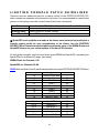
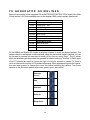
PERSONALITY - Status Settings - Address Via DMX
When ON, define the desired DMX address via an external controller.
NOTE: This process assumes the fixture DMX address is set to 001. If fixture DMX address is not at 001,
you must adjust the channel numbers accordingly in order for this feature to work.
For example: if your fixture address is 010, then Channel 1 becomes Channel 10, Channel 2 becomes
Channel 11, and Channel 3 becomes Channel 12.
1. Connect the fixture to the external controller and power ON.
2. Set the DMX value of Channel 1 on the controller to (7).
3. Set the DMX value of Channel 2 on the controller to (7) or (8).
When set to (7), the DMX address can be set between (1) and (255).
When set to (8), the DMX address can be set between (256) and (511).
4. Using Channel 3 on the controller set the desired DMX address of the fixture.
Example 1: If the desired DMX address is 57, set Channel 1 to a value of (7), set Channel
2 to a value of (7), and then set Channel 3 to a value of (57).
Example 2: If the desired DMX address is 420, set Channel 1 to a value of (7), set
Channel 2 to a value of (8), and then set Channel 3 to a value of (164). (256+164=420)
5. After setting Channel 3 to the desired DMX address value, wait for approximately 20
seconds (some fixtures may require a longer time) for the fixture to complete the address
reset function.
PERSONALITY – Service Setting - Password (050)
The Service Password MUST be entered in order to access the service menus.

19
SYSTEM MENU
PERSONALITY – Service Setting – USB Update
To update the fixture software via the UPDATE/SERVICE PORT, follow steps below.
ONLY QUALIFIED TECHNICIANS SHOULD PERFORM THIS FUNCTION!
NOTE ALL MENU SETTINGS BEFORE UPDATING SOFTWARE!
FIXTURE SOFTWARE CAN NOT BE DOWNGRADED!
DOWNLOAD FIXTURE SOFTWARE TO PC ONLY! (NO MAC SUPPORT)
PLEASE CONTACT ELATION SERVICE FOR FURTHER INFORMATION.
1. Copy fixture software update file from a PC computer to a compatible USB flash drive.
Make sure only the fixture software update file is stored on the USB flash drive.
2. Disconnect DMX, Art-Net, and E-FLY connections and power the fixture ON.
3. Insert USB flash drive into the UPDATE/SERVICE PORT on the rear connection panel.
4. Navigate to the Personality main menu Service Setting / USB Update sub menu.
5. Select the software file name on the menu display and press ENTER.
6. Select YES to begin update process and Updating…% will show on the menu display.
7. After file is uploaded, the fixture will check the software which will take some time.
The fixture will perform a reset process when the software update process is complete.
8. Remove the USB flash drive and make necessary system menu setting adjustments.
PERSONALITY - Display Setting – Key Lock
When ON, Control Panel buttons lock automatically after exiting main menu for 15
seconds. To unlock, keep MODE/ESC button pressed for 3 seconds.
PERSONALITY - Reset Default (011)
ONLY QUALIFIED TECHNICIANS SHOULD PERFORM THIS FUNCTION!
NOTE: SAVED WHITE BALANCE IS ERASED AFTER A RESET IS PERFORMED!
This function restores all fixture settings to the factory default settings. The password is
011 and must be entered each time a reset is performed.

20
SYSTEM MENU
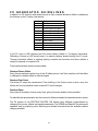
EFFECT ADJUST – Test Channel
Auto test each individual channel function independently from the DMX control board.
EFFECT ADJUST – Manual Control
Select and manually test and fine adjust each individual channel function
Independently from DMX control board. This function will center PAN and TILT motors and
set dimmer to 100%. PAN and TILT functions will still operate if the fixture needs to be
positioned to a flat clear surface. With the individual functions, you can focus the light on a
flat surface (wall) and perform fine adjustments.
EFFECT ADJUST – Calibration
ONLY QUALIFIED TECHNICIANS SHOULD PERFORM THIS FUNCTION.
This function allows small adjustments to be made to the Pan, Tilt, and Zoom movements
to compensate for ware or in the event a sensor has been knocked slightly out of place.
Because improper use of this function can result in undesired operation this function has
been password protected. The password is 050 and must be entered each time the
calibration menu function is entered. Because calibration is an extremely delicate procedure,
instructions on performing this action are left out of this manual. For a first-time calibrator,
please contact our customer support team for step-by-step instructions.
EDIT PROGRAM – Rec. Controller
The fixture features an integrated DMX-recorder by which you can transmit the programmed
scenes from your DMX-controller to the moving head. Adjust the desired scene numbers via
the encoder (from – to). When you call up the scenes at your controller, they will
automatically be transmitted to the moving head.
La pagina sta caricando ...
La pagina sta caricando ...
La pagina sta caricando ...
La pagina sta caricando ...
La pagina sta caricando ...
La pagina sta caricando ...
La pagina sta caricando ...
La pagina sta caricando ...
La pagina sta caricando ...
La pagina sta caricando ...
La pagina sta caricando ...
La pagina sta caricando ...
La pagina sta caricando ...
La pagina sta caricando ...
La pagina sta caricando ...
La pagina sta caricando ...
La pagina sta caricando ...
La pagina sta caricando ...
La pagina sta caricando ...
La pagina sta caricando ...
La pagina sta caricando ...
La pagina sta caricando ...
La pagina sta caricando ...
La pagina sta caricando ...
La pagina sta caricando ...
La pagina sta caricando ...
La pagina sta caricando ...
La pagina sta caricando ...
La pagina sta caricando ...
La pagina sta caricando ...
La pagina sta caricando ...
La pagina sta caricando ...
La pagina sta caricando ...
La pagina sta caricando ...
La pagina sta caricando ...
La pagina sta caricando ...
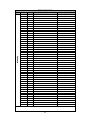
-
 1
1
-
 2
2
-
 3
3
-
 4
4
-
 5
5
-
 6
6
-
 7
7
-
 8
8
-
 9
9
-
 10
10
-
 11
11
-
 12
12
-
 13
13
-
 14
14
-
 15
15
-
 16
16
-
 17
17
-
 18
18
-
 19
19
-
 20
20
-
 21
21
-
 22
22
-
 23
23
-
 24
24
-
 25
25
-
 26
26
-
 27
27
-
 28
28
-
 29
29
-
 30
30
-
 31
31
-
 32
32
-
 33
33
-
 34
34
-
 35
35
-
 36
36
-
 37
37
-
 38
38
-
 39
39
-
 40
40
-
 41
41
-
 42
42
-
 43
43
-
 44
44
-
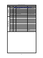 45
45
-
 46
46
-
 47
47
-
 48
48
-
 49
49
-
 50
50
-
 51
51
-
 52
52
-
 53
53
-
 54
54
-
 55
55
-
 56
56


Elation PROTEUS RAYZOR 760 WMG Manuale utente
- Categoria
- Stroboscopi
- Tipo
- Manuale utente
- Questo manuale è adatto anche per
in altre lingue
Documenti correlati
Altri documenti
-
Cameo EVOS® W7 Manuale utente
-
-
Soundstream MTR-25-10W-RGBW Manuale utente
-
-
-
SGM Idea Par LED Zoom RGB Manuale utente
-
PROEL PLBR256MH2 - REV 07-2006 Manuale utente
-
CHAUVET DJ DMX-AN Guida di riferimento
-
ColorKey CKU-7010 Manuale utente
-
 LSC AXIOM Manuale utente
