Hangar 9 HAN2345 Manuale del proprietario
- Categoria
- Giocattoli telecomandati
- Tipo
- Manuale del proprietario
Questo manuale è adatto anche per

Ultra Stick
™
10cc
Instruction Manual
Bedienungsanleitung
Manuel d’utilisation
Manuale di Istruzioni

2
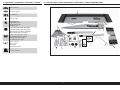
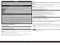
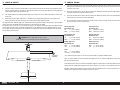
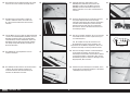
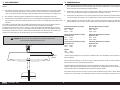
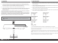
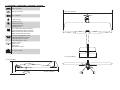
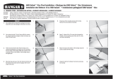
SPECIFICATIONS • SPEZIFIKATIONEN • SPÉCIFICATIONS • SPECIFICHE LARGE PARTS LAYOUT • BAUTEILE (OHNE KLEINTEILE) • GRANDES PIÈCES • SCHEMA DEI COMPONENTI GRANDI
60.0 in (1524 mm)
810 sq in (52.3 dm2)
57 in (1448 mm)
7.0 lbs (3.18 kg)
2-Stroke Gas: 10cc
2-Takt Benziner: 10cc
2 temps Essence: 10cc
2-Tempi Gas: 10cc
Electric Power Power: Power 52 Brushless
Elektro Antrieb Power: Power 52 Brushless
Moteur électrique (EP): Power 52 Brushless
Motore elettrico: Power 52 Brushless
4-channel (or greater) with 5 servos
4-Kanal (oder größer) mit 5-Servos
4 voies (ou plus) avec 5 servos
a 4 canali (o più) con 5 servo
Spinner: 2.25-inch
Spinner: 57mm
Cône: 57mm
Ogiva dell’elica: 57mm
4
3
/
4
inches (122mm)
3
2
7
9
10
11
4
5
6
1
12
16
17
15
14
13
8

3
Ultra Stick
™
10cc
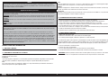
Part # English Deutsch Français Italiano
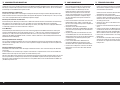
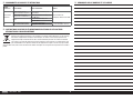
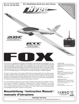
REPLACEMENT PARTS • ERSATZTEILE • PIÈCES DE RECHANGE • PEZZI DI RICAMBIO
1 HAN234501 Fuselage Rumpf Fuselage Fusoliera
2 HAN234502 Wing with Ailerons and Flaps Flügel mit Querrudern und Klappen Aile avec ailerons et volets Ala con alettoni e fl ap
3 HAN234503 Fin and Rudder Finne u. Seitenruder Dérive et sa gouverne Direzionale e timone
4 HAN234504 Stabilizer and Elevator Höhenruderset Set Plan horizontal et Gouverne de profondeur Set stabilizzatore ed elevatore
5 HAN234506 Landing Gear Set Fahrwerk Set Train d’atterrissage Set del carrello di atterraggio
6 HAN234507 Wheel Pants Radverkleidung Carénage de roue Copriruote
7 HAN234508 Aileron and Flap, Right-Hand Querruder und Klappe, rechte Seite Aileron et volet, côté droit Alettone e fl ap, destro
8 HAN234509 Aileron and Flap, Left-Hand Querruder und Klappe, linke Seite Aileron et volet, côté gauche Alettone e fl ap, sinistro
9 HAN234510 Aileron Set (Not Included) Querrudersatz (Nicht enthalten) Paire d’ailerons (Non fourni) Set alettoni (Non inclusa)
10 HAN234511 Hardware Set Kleinteile Set Sachet de visserie Set dei pezzi
11 HAN234513 Fuselage Hatch Rumpfklappe Capot du fuselage Portello della fusoliera
12 HAN234514 Wheels Räder Roues Ruote
13 HAN234515 EP Tray EP-Halterung Support EP Supporto motore elettrico
14 HAN234517 Tail Wheel Assembly Spornrad m. Zbh. Assemblage de roulette de queue Gruppo del ruotino di coda
15 HAN234518 Fuel tank 15oz Kraftstofftank Réservoir de carburant Serbatoio carburante
16 HAN234519 Engine Mount Set Motor-Montagesatz Jeu de renfort moteur Set di montaggio motore
17 HAN234520 Spinner: 2.25-inch Spinner: 57mm Cône: 57mm Ogiva dell’elica: 57mm
SMALL PARTS (NOT SHOWN)•KLEINTEILE (NICHT ABGEBILDET)•PETITES PIÈCES (NON REPRÉSENTÉES)•PARTI DI PICCOLE DIMENSIONI (NON MOSTRATE)
HAN234512 Decal Set Dekorbogen Planche de décoration Set di decalcomanie
HAN234516 Pushrod Set Gestänge / Anlenkungen Set Jeu de tringleries Set dell’asta di spinta
ELECTRIC POWER • ELEKTROANTRIEB • MOTEUR ELECTRIQUE (EP) • MOTORE ELETTRICO
APC14085E Electric Propeller, 14 x 8.5E Elektro Propeller, 14 x 8,5E Hélice électrique, 14 x 8,5E Elica elettrica sottile, 14 x 8,5E
EFLA1060B 60-Amp Pro SB Brushless ESC (V2) 60-Amp Pro SB Brushless ESC (V2) Variateur ESC sans balais avec circuit SB pro 60 A (V2) 60-Amp Pro SB Brushless ESC (V2)
EFLAEC509 or EC5 Device To EC3 Battery 1.5-inch, 12 AWG EC5-Gerät an EC3-Akku 76mm (1,5 Zoll), 12AWG Dispositif EC5 vers batterie EC3, 1,5po, 12AWG
Adattatore dispositivo EC5 a batteria EC3 3,8 cm
(1,5’’), 12 AWG
EFLAEC501 EC5 Device Connector (2) EC5 Gerät-Steckverbinder (2) Connecteur du dispositif EC5 (2) Connettore dispositivo EC5 (2)
EFLB50005S30 5000mAh 5S 18.5V 30C LiPo,12AWG EC3 5000mA 5S 18,5 V 30C LiPo-Akku,12 AWG EC3
Batterie Li-Po 5S 18,5V 5000mA 30C, 12AWG prise
EC3
Batteria LiPo 30C 18,5 V 5S 5000 mAh, 12AWG
EC3
EFLM4052A Power 52 BL Outrunner Mtr, 590Kv Bürstenloser Außenläufer-Motor Leistung 52, 590Kv
Moteur à cage tournante sans balais Power 52 de
590Kv
Motore brushless a cassa rotante Power 52,
590Kv
SPMSA6110 x6 A6110 HV Standard Servo A6110 HV Standard Servo Servo standard A6110 HV Servo standard A6110 HV

4
Part # English Deutsch Français Italiano
2-STROKE GAS • 2-TAKT BENZINER • 2 TEMPS ESSENCE • 2-TEMPI A BENZINA
APC12060 Sport Propeller, 12 x 6 Sportpropeller, 12 x 6 Hélice sport, 12 x 6 Elica sport, 12 x 6
EVOA112 Evolution 3 Wire Ignition/RX Switch Evolution Zündschalter Interrupteur Evolution 3 fi ls Allumage/RX
Evolution, interruttore a 3 fi li accensione/
ricevitore
EVOE10GX2 10GX Gas Engine w/ Pumped Carb Evolution 10-cc Evolution 10-cc Evolution 10-cc
SPM9530 Spektrum
™
3-Wire Switch Harness Spektrum dreiadriges Schalterkabel Câblage d’interrupteur 3 fi ls Spektrum Interruttore di accensione a 3 fi li Spektrum
SPMB2000LPRX 2000mAh 2S 7.4V LiPo Rx Battery LiPo-Empfängerakku (7,4 V / 2000 mAh) Batterie Li-Po de récepteur 7,4 V 2000 mAh Batteria per ricevitore da 7,4 V Li-Po, 2000 mAh
SPMB900LFRX 900mAh 2S 6.6V Li-Fe Rx Battery 900 mA 2S 6,6 V LiFe Empfänger-Akku Batterie récepteur Li-Fe 2S 6,6V 900mA Batteria LiFe per ricevente 2S 6,6 V 900 mAh
SPMSA6110 x7 A6110 HV Standard Servo A6110 HV Standard Servo Servo standard A6110 HV Servo standard A6110 HV
EVOA102 Medium Gas-FKM Fuel Tubing (1 meter) Mittlere Gas-FKM Kraftstoffl eitung (1 Meter) Tuyau de carburant en FKM moyen (1 mètre) Tubo per combustibile FKM medio (1 metro)
REQUIRED RADIO EQUIPMENT • ERFORDERLICHE RC AUSRÜSTUNG • ÉQUIPEMENT RADIO REQUIS • APPARECCHIATURE RADIO NECESSARIE
SPMA3000 x2 Heavy-Duty Servo Extension 3-inch Servokabelverlängerung 75 mm (3 inch) Rallonge de servo, 75 mm Estensione servo 3 pollici
SPMA3001 x4 Heavy-Duty Servo Extension 6-inch Servokabelverlängerung 150 mm (6 inch) Rallonge de servo, 150 mm Estensione servo 6 pollici
SPMA3002 x2 Heavy-Duty Servo Extension 9-inch Servokabelverlängerung 230 mm (9 inch) Rallonge de servo, 230 mm Estensione servo 9 pollici
SPMAR7350 AR7350 7 Channel AS3X Receiver AR7350 7 Kanal AS3X RX mit integrierter Telemetrie
Récepteur Spektrum AR7350 7 voies AS3X avec
télémétrie intégrée
Ricevente AR7350 AS3X 7 canali con telemetria
integrata
OPTIONAL ITEMS • OPTIONALE TEILE • ÉLÉMENTS OPTIONNELS • ARTICOLI OPZIONALI
DYNC2010CA Prophet Sport Plus 50W AC/DC Charger
Prophet Sport Plus 50W Wechsel-/Gleichstrom-
Ladegerät
Chargeur CA/CC 50W Prophet Sport Plus Caricabatterie Prophet Sport Plus 50W AC
SPMA3054 Servo Connector Clips (25) Servosteckerklemmen (25) Attaches de connexion du servo (25) Morsetti servocomando (25)
SPMAR9350 AR9350 9-Channel AS3X Receiver AR9350 AS3X-Empfänger mit 9 Kanälen Récepteur AS3X 9canaux AR9350 Ricevitore AS3X a 9 canali AR9350
OPTIONAL FLOATS•OPTIONALE SCHWIMMER•FLOTTEURS OPTIONNELS•GALLEGGIANTI OPZIONALI
EFLA5600 Carbon-Z Float Set Carbon-ZSchwimmersatz Ensemble de fl otteurs Carbon-Z Set galleggianti Carbon-Z
EFLA5605
Wire Mounting Set for CZ Cessna 150:
Carbon-Z Floats
Kabelbefestigungssatz CZ für Cessna 150:
Carbon-ZSchwimmer
Ensemble pour montage de câbles pour CZ Cessna
150: fl otteurs Carbon-Z
Set montaggio fi li per CZ Cessna 150:
Galleggianti Carbon-Z
SPMA3001 Heavy-Duty Servo Extension 6-inch Servokabelverlängerung 150 mm (6 inch) Rallonge de servo, 151 mm Estensione servo 6 pollici
SPMA3058 Standard Y-Harness, 6-inch Standard Y-Kabelbaum, 152mm (6 Zoll) Rallonge Y standard, 15cm Cavo a Y standard, 6''
DUB158 Landing Gear Straps Halteriemen des Fahrwerks Sangles du train d’atterrissage Piastrine carrello d’atterraggio
REQUIRED ADHESIVES • ERFORDERLICHE KLEBSTOFFE • TYPES DE COLLES • ADESIVI NECESSARI
DLMAD44 Roket Rapid CA 5-10 sec: 20g Roket Rapid CA 5-10 s: 20g Colle cyano Roket Rapid 5-10 sec: 20g Colla cianoacrilica Roket Rapid 5-10 sec: 20 g
DLMAD45 Roket Max CA 10-20 sec: 20g Roket Max CA 10-20 s: 20g Colle cyano Roket Max 10-20 sec: 20g Colla cianoacrilica Roket Max 10-20 sec: 20 g
PAAPT715 CA Accelerator Sekundenkleber (CA) Aktivator Accélérateur de colle CA Accelerante colla CA
PAAPT35 15-Minute Epoxy 15 Minuten Epoxy Époxy 15 minutes Colla epoxy 15 minuti
PAAPT42 Threadlock Schraubensicherungslack Frein-fi let Frenafi letti
DLMAD12 R/C Modeller Canopy Glue: 4 oz R/C Modeller Kanzelkleber: 113,4g (4 oz) Colle à verrière R/C Modeller: 113g Colla per capottine R/C Modeller: 4 oz

5
Ultra Stick
™
10cc
Part # English Deutsch Français Italiano
REQUIRED TOOLS • BENÖTIGTES WERKZEUG • OUTILS REQUIS • ATTREZZI NECESSARI
Box wrench: 1/2-inch Ringschlüssel: 1/2-inch Clé hexagonale: 1/2-inch Chiave esagonale: 1/2-inch
Drill Bohrer Mini-perceuse Trapano
Drill bit: 1/16-inch, 5/64-inch, 1/8-inch
5/32-inch, 3/16-inch
Bohrer: 1,5mm, 2mm, 3mm, 4mm, 4,5mm Forêt : 1,5mm, 2mm, 3mm, 4mm, 4,5mm
Punte per trapano: 1,5mm, 2mm, 3mm, 4mm,
4,5mm
Felt-tipped pen Faserstift Feutre fi n effaçable Pennarello
Epoxy brush Pinsel Pinceau Epoxy Spazzole epoxy
Flat fi le Flachfeile Lime plate Lima piatta
Hemostats Klemme Pince Hemostat Pinzetta
Hex wrench: 3/32-inch, 1.5mm, 2mm, 2.5mm,
3mm, 4mm
Inbusschlüssel: 3/32-inch, 1,5mm, 2mm, 2,5mm,
3mm, 4mm
Tournevis hexagonal: 3/32-inch, 1,5mm, 2mm, 2,5mm,
3mm, 4mm
Chiave esag.: 3/32-inch, 1,5mm, 2mm, 2,5mm,
3mm, 4mm
Hobby knife with #11 blade Hobbymesser mit # 11 Klinge Couteau : Lame numéro 11 Taglierino: #11 lama
Isoplrpyl alcohol Isopropyl Alkohol Alcool isopropylique Alcol isopropilico
Low-tack tape Kreppband Adhésif de masquage Nastro a bassa aderenza
Needle nose pliers Spitzzange Pince fi ne Pinze a becco stretto
Nut driver: 1/4-inch, 4mm, 5.5mm Steckschlüssel. 1/4-inch, 11/32-inch Clés à douilles : 1/4-inch, 11/32 pouce Chiave per dadi: 1/4-inch, 11/32-inch
Paper towels Papiertücher Papier absorbant Asciugamani di carta
Pencil Stift Crayon à papier Matita
Phillips screwdriver: #1 Phillips Schraubendreher: #1 Tournevis cruciforme: #1 Cacciavite a croce: #1
Pin vise Handbohrer Porte forets Trapano manuale
Pliers Zange Pince Pinze
Ruler Lineal Réglet Righello
Sandpaper Schleifpapier Papier de verre Carta vetrata
Scissors Schere Ciseaux Forbici
Side cutters Seitenschneider Pince coupante Lama laterale
Square Geodreieck Équerre Squadra
Tap and drill set, English Gewindeschneider und Bohrerset Taraud et foret Set punte e maschi, Inglese
Tap Handle Halter für Gewindeschneider Épingles Impugnatura per maschiare
T-pins T- Nadeln Epingles Spilli a T
Toothpicks Zahnstocher Cure dents Stuzzicadenti

6
NOTICE
All instructions, warranties and other collateral documents are subject to change at the sole discretion of Horizon
Hobby, LLC. For up-to-date product literature, visit horizonhobby.com and click on the support tab for this product.
The following terms are used throughout the product literature to indicate various levels of potential harm when
operating this product:
Meaning of Special Language
WARNING: Procedures, which if not properly followed, create the probability of property damage, collateral damage,
and serious injury OR create a high probability of superfi cial injury.
CAUTION: Procedures, which if not properly followed, create the probability of physical property damage AND a
possibility of serious injury.
NOTICE: Procedures, which if not properly followed, create a possibility of physical property damage AND a little or
no possibility of injury.
WARNING: Read the ENTIRE instruction manual to become familiar with the features of the product before operating.
Failure to operate the product correctly can result in damage to the product, personal property and cause serious
injury.
This is a sophisticated hobby product. It must be operated with caution and common sense and requires some basic
mechanical ability. Failure to operate this Product in a safe and responsible manner could result in injury or damage
to the product or other property. This product is not intended for use by children without direct adult supervision. Do
not attempt disassembly, use with incompatible components or augment product in any way without the approval
of Horizon Hobby, LLC. This manual contains instructions for safety, operation and maintenance. It is essential to
read and follow all the instructions and warnings in the manual, prior to assembly, setup or use, in order to operate
correctly and avoid damage or serious injury.
AGE RECOMMENDATION: NOT FOR CHILDREN UNDER 14 YEARS. THIS IS NOT A TOY.
USING THE MANUAL
This manual is divided into sections to help make assembly easier to understand.
SAFETY WARNINGS AND PRECAUTIONS
Read and follow all instructions and safety precautions before use. Improper use can result in fi re, serious injury and
damage to property.
Components
Use only with compatible components. Should any compatibility questions exist, please refer to the product
instructions, component instructions or contact the appropriate Horizon Hobby offi ce.
Flight
Fly only in open areas to ensure safety. It is recommended fl ying be done at radio control fl ying fi elds. Consult local
ordinances before choosing a fl ying location.
Propeller
Keep loose items that can become entangled in the propeller away from the prop. This includes loose clothing or other
objects such as pencils and screwdrivers. Keep your hands away from the propeller as injury can occur.
Batteries
Always follow the manufacturer’s instructions when using and disposing of any batteries. Mishandling of Li-Po
batteries can result in fi re causing serious injury and damage.
Small Parts
This kit includes small parts and should not be left unattended near children as choking and serious injury could result.
SAFE OPERATING RECOMMENDATIONS
• Inspect your model before every fl ight to ensure it is airworthy.
• Be aware of any other radio frequency user who may present an interference problem.
• Always be courteous and respectful of other users in your selected fl ight area.
• Choose an area clear of obstacles and large enough to safely accomodate your fl ying activity.
• Make sure this area is clear of friends and spectators prior to launching your aircraft.
• Be aware of other activities in the vicinity of your fl ight path that could cause potential confl ict.
• Carefully plan your fl ight path prior to launch.
• Abide by any and all established AMA National Model Aircraft Safety Code.
BEFORE STARTING ASSEMBLY
• Remove parts from bag.
• Inspect fuselage, wing panels, rudder and stabilizer for damage.
• If you fi nd damaged or missing parts, contact your place of purchase.
If you fi nd any wrinkles in the covering, use a heat gun (HAN100) and covering glove (HAN150) or covering iron
(HAN101) with a sealing iron sock (HAN141) to remove them. Use caution while working around areas where the colors
overlap to prevent separating the colors.
• Charge transmitter and receiver batteries.
• Center trims and sticks on your transmitter.
• For a computer radio, create a model memory for this particular model.
• Bind your transmitter and receiver, using your radio system’s instructions.
IMPORTANT: Rebind the radio system once all control throws are set. This will keep the servos from moving to
their endpoints until the transmitter and receiver connect. It will also guarantee the servo reversal settings are
saved in the radio system.

7
Ultra Stick
™
10cc
Propeller
Halten Sie lose Gegenstände die sich im Propeller verfangen können weg vom Propeller. Dieses gilt auch für Kleidung
oder andere Objekte wie zum Beispiel Stifte oder Schraubendreher.
Halten Sie ihre Hände weg vom Propeller, es besteht akute Verletzungsgefahr.
Akkus
Folgen Sie immer den Herstelleranweisungen bei dem Gebrauch oder Entsorgung von Akkus. Falsche Behandlung von
LiPo Akkus kann zu Feuer mit Körperverletzungen und Sachbeschädigung führen.
Kleinteile
Dieser Baukasten beinhaltet Kleinteile und darf nicht unbeobachtet in der Nähe von Kindern gelassen werden, da die
Teile verschluckt werden könnten mit ernsthaften Verletzung zur Folge.
EMPFEHLUNGEN ZUM SICHEREN BETRIEB
• Überprüfen Sie zur Flugtauglichkeit ihr Modell vor jedem Flug.
• Beachten Sie andere Piloten deren Sendefrequenzen ihre Frequenz stören könnte.
• Begegnen Sie anderen Piloten in ihrem Fluggebiet immer höfl ich und respektvoll.
• Wählen Sie ein Fluggebiet, dass frei von Hindernissen und groß genug ist.
• Stellen Sie vor dem Start sicher, dass die Fläche frei von Freunden und Zuschauern ist.
• Beobachten Sie den Luftraum und andere Flugzeuge/Objekte die ihren Flugweg kreuzen und zu einem Konfl ikt
führen könnten.
• Planen Sie sorgfältig ihren Flugweg vor dem Start.
VOR DEM ZUSAMMENBAU
• Entnehmen Sie zur Überprüfung jedes Teil der Verpackung.
• Überprüfen Sie den Rumpf, Tragfl ächen, Seiten- und Höhenruder auf Beschädigung.
• Sollten Sie beschädigte oder fehlende Teile feststellen, kontaktieren Sie bitte den Verkäufer.
Zum Entfernen von Falten in der Bespannung verwenden Sie den Heißluftfön (HAN100) und Bespannhandschuh
(HAN150) oder das Folienbügeleisen (HAN141). Bitte achten Sie bei überlappenden Farben, dass Sie diese sich bei
dem Bearbeitung nicht trennen.
• Laden des Senders und Empfängers.
• Zentrieren der Trimmungen und Sticks auf dem Sender.
• Sollten Sie einen Computersender verwenden, resetten Sie einen Speicherplatz und benennen ihn nach dem Modell.
• Sender und Empfänger jetzt nach den Bindeanweisung des Herstellers zu binden.
WICHTIG: Wir empfehlen dringend nachdem alle Einstellungen vorgenommen worden sind, das Modell neu zu binden.
Dieses verhindert, dass die Servos in die Endanschläge laufen bevor sich Sender und Empfänger verbunden haben. Es
garantiert auch, dass die Servoreverseeinstellungen in der RC Anlage gesichert sind.
HINWEIS
Alle Anweisungen, Garantien und anderen zugehörigen Dokumente können im eigenen Ermessen von Horizon Hobby,
LLC. jederzeit geändert werden Die aktuelle Produktliteratur fi nden Sie auf horizonhobby.com unter der Registerkarte
„Support“ für das betreffende Produkt.
Spezielle Bedeutungen
Die folgenden Begriffe werden in der gesamten Produktliteratur verwendet, um auf unterschiedlich hohe
Gefahrenrisiken beim Betrieb dieses Produkts hinzuweisen:
WARNUNG: Wenn diese Verfahren nicht korrekt befolgt werden, ergeben sich wahrscheinlich Sachschäden,
Kollateralschäden und schwere Verletzungen ODER mit hoher Wahrscheinlichkeit oberfl ächliche Verletzungen.
ACHTUNG: Wenn diese Verfahren nicht korrekt befolgt werden, ergeben sich wahrscheinlich Sachschäden UND die
Gefahr von schweren Verletzungen.
HINWEIS: Wenn diese Verfahren nicht korrekt befolgt werden, können sich möglicherweise Sachschäden UND geringe
oder keine Gefahr von Verletzungen ergeben.
WARNUNG: Lesen Sie die GESAMTE Bedienungsanleitung, um sich vor dem Betrieb mit den Produktfunktionen
vertraut zu machen. Wird das Produkt nicht korrekt betrieben, kann dies zu Schäden am Produkt oder persönlichem
Eigentum führen oder schwere Verletzungen verursachen.
Dies ist ein hochentwickeltes Hobby-Produkt. Es muss mit Vorsicht und gesundem Menschenverstand betrieben
werden und benötigt gewisse mechanische Grundfähigkeiten. Wird dieses Produkt nicht auf eine sichere und
verantwortungsvolle Weise betrieben, kann dies zu Verletzungen oder Schäden am Produkt oder anderen Sachwerten
führen. Dieses Produkt eignet sich nicht für die Verwendung durch Kinder ohne direkte Überwachung eines
Erwachsenen. Verwenden Sie das Produkt nicht mit inkompatiblen Komponenten oder verändern es in jedweder Art
ausserhalb der von Horizon Hobby, LLC vorgegebenen Anweisungen. Diese Bedienungsanleitung enthält Anweisungen
für Sicherheit, Betrieb und Wartung. Es ist unbedingt notwendig, vor Zusammenbau, Einrichtung oder Verwendung
alle Anweisungen und Warnhinweise im Handbuch zu lesen und zu befolgen, damit es bestimmungsgemäß betrieben
werden kann und Schäden oder schwere Verletzungen vermieden werden.
NICHT GEEIGNET FÜR KINDER UNTER 14 JAHREN. DIES IST KEIN SPIELZEUG.
ÜBER DIESE ANLEITUNG
Diese Anleitung ist zur Vereinfachung des Zusammenbaues in Sektionen unterteilt.
WARNUNGEN UND SICHERHEITS-VORKEHRUNGEN
Bitte lesen und befolgen Sie alle Anweisungen und Sicherheitsvorkehrungen vor dem Gebrauch. Falscher, nicht
sachgemäßer Gebrauch kann Feuer, ernsthafte Verletzungen und Sachbeschädigungen zur Folge haben.
Komponenten
Verwenden Sie mit dem Produkt nur kompatible Komponenten. Sollten Fragen zur Kompatibilität auftreten, lesen Sie
bitte die Produkt- oder Bedienungsanweisung oder kontaktieren den Service von Horizon Hobby.
Fliegen
Fliegen Sie um Sicherheit garantieren zu können, nur in weiten offenen Gegenden. Wir empfehlen hier den Betrieb auf
zugelassenen Modellfl ugplätzen. Bitte beachten Sie lokale Vorschriften und Gesetze, bevor Sie einen Platz zum Fliegen
wählen.

8
L’hélice
Gardez éloignés tous les éléments qui pourraient être attrapés par l’hélice. Cela inclut les vêtements larges ou les
objets comme des outils par exemple. Gardez toujours vos mains à distance pour éviter tout cas de blessures.
Les batteries
Suivez toujours les instructions du fabricant de vos batteries. Une mauvaise manipulation d’une batterie Li-Po peut
entraîner un incendie causant de graves dégâts matériels et des blessures corporelles.
Petites pièces
Ce kit contient des petites pièces qui ne doivent pas être laissées à la portée des enfants, ces pièces sont dangereuses
pour eux et peuvent entraîner de graves blessures.
CONSIGNES DE SÉCURITÉ CONCERNANT L’UTILISATION
• Inspectez votre modèle avant chaque vol.
• Surveillez les fréquences utilisées à proximité.
• Soyez toujours courtois et respectueux des autres utilisateurs de la zone de vol.
• Choisissez une zone dégagée de tout obstacle et suffi samment grande pour voler en toute sécurité.
• Contrôlez que la zone est libre de spectateurs avant de lancer votre modèle.
• Soyez conscient des autres activités aux alentours de votre vol, risque de confl it potentiel.
• Planifi ez votre vol avant de le commencer.
AVANT DE COMMENCER L’ASSEMBLAGE
• Retirez toutes les pièces des sachets pour les inspecter.
• Inspectez soigneusement le fuselage, les ailes et les empennages.
• Si un élément est endommagé, contactez votre revendeur.
Si l’entoilage présente quelque plis, vous pouvez les lisser en utilisant le pistolet à air chaud (HAN100) et le gant
(HAN150) ou le fer à entoiler (HAN101) avec la chaussette de protection (HAN141). Agissez soigneusement dans les
zones où plusieurs couleurs d’entoilage sont superposées afi n d’éviter de les séparer.
• ll est recommandé de préparer tous les éléments du système de la radio.
• Cela inclut la charge des batteries comme la mise au neutre des trims et des manches de votre émetteur.
• Si vous utilisez une radio programmable, sélectionnez une mémoire libre afi n d’y enregistrer les paramètres de ce
modèle.
• Nous vous recommandons d’affecter maintenant le récepteur à l’émetteur en suivant les instructions fournies avec
votre radio.
IMPORTANT: Il est hautement recommandé de ré-affecter le système une fois que les courses seront réglées. Cela
empêchera les servos d’aller en butée lors de la connexion du système. Cela garantit également que la direction des
servos est enregistrée dans l’émetteur.
REMARQUE
La totalité des instructions, garanties et autres documents est sujette à modifi cation à la seule discrétion d’Horizon
Hobby, LLC. Pour obtenir la documentation àjour, rendez-vous sur le site horizonhobby.com et cliquez sur l’onglet de
support de ce produit.
Signifi cation de certains termes spécifi ques
Les termes suivants sont utilisés dans l’ensemble du manuel pour indiquer différents niveaux de danger lors de
l’utilisation de ce produit:
AVERTISSEMENT: Procédures qui, si elles ne sont pas suivies correctement, peuvent entraîner des dégâts matériels
et des blessures graves OU engendrer une probabilité élevée de blessure superfi cielle.
ATTENTION: Procédures qui, si elles ne sont pas suivies correctement, peuvent entraîner des dégâts matériels ET des
blessures graves.
REMARQUE: Procédures qui, si elles ne sont pas suivies correctement, peuvent entraîner des dégâts matériels ET
éventuellement un faible risque de blessures.
AVERTISSEMENT: Lisez la TOTALITÉ du manuel d’utilisation afi n de vous familiariser avec les caractéristiques du
produit avant de le faire fonctionner. Une utilisation incorrecte du produit peut entraîner sa détérioration, ainsi que des
risques de dégâts matériels, voire de blessures graves.
Ceci est un produit de loisirs sophistiqué. Il doit être manipulé avec prudence et bon sens et requiert des aptitudes
de base en mécanique. Toute utilisation irresponsable de ce produit ne respectant pas les principes de sécurité peut
provoquer des blessures, entraîner des dégâts matériels et endommager le produit. Ce produit n’est pas destiné à
être utilisé par des enfants sans la surveillance directe d’un adulte. N’essayez pas de modifi er ou d’utiliser ce produit
avec des composants incompatibles hors des instructions fournies par Horizon Hobby, LLC. Ce manuel comporte des
instructions relatives à la sécurité, au fonctionnement et à l’entretien. Il est capital de lire et de respecter la totalité
des instructions et avertissements du manuel avant l’assemblage, le réglage et l’utilisation, ceci afi n de manipuler
correctement l’appareil et d’éviter tout dégât matériel ou toute blessure grave.
14 ANS ET PLUS. CECI N’EST PAS UN JOUET.
UTILISATION DU MANUEL
Ce manuel est divisé en sections pour vous aider à comprendre plus facilement l’assemblage.
AVERTISSEMENTS RELATIFS À LA SÉCURITÉ
Lisez et suivez toutes les instructions relatives à la sécurité avant utilisation. Une utilisation inappropriée peut entraîner
un incendie, de graves blessures et des dégâts matériels.
Composants
Utilisez uniquement des composants compatibles. Si vous avez des questions concernant la compatibilité, référez-vous
à ce manuel ou contactez le service technique Horizon Hobby.
Le vol
Volez uniquement dans des zones dégagées pour un maximum de sécurité. Il est recommandé d’utiliser les pistes des
clubs d’aéromodélisme. Consultez votre mairie pour connaître les sites autorisés.

9
Ultra Stick
™
10cc
AVVISO
Tutte le istruzioni, le garanzie e gli altri documenti pertinenti sono soggetti a cambiamenti a totale discrezione di
Horizon Hobby, LLC. Per una documentazione aggiornata sul prodotto, visitare il sito www.horizonhobby.com e fare
clic sulla sezione Support per questo prodotto.
Signifi cato dei termini particolari
In tutta la documentazione relativa al prodotto sono utilizzati iseguenti termini per indicare vari livelli di potenziale
pericolo durante il funzionamento:
AVVERTENZA: Procedure che, se non debitamente seguite, espongono alla possibilità di danni alla proprietà fi sica
opossono omportare un’elevata possibilità di provocare ferite superfi ciali. Ulteriori precauzioni per la sicurezza e
avvertenze.
ATTENZIONE: Procedure che, se non sono seguite correttamente, possono creare danni materiali E possibili gravi
lesioni.
AVVISO: Procedure che, se non sono seguite correttamente, possono creare danni materiali E nessuna oscarsa
possibilità di lesioni.
AVVERTENZA: Leggere TUTTO il manuale di istruzioni e prendere familiarità con le caratteristiche del prodotto, prima
di farlo funzionare. Un utilizzo scorretto del prodotto può causare danni al prodotto stesso, alle persone oalle cose,
provocando gravi lesioni.
Questo è un prodotto di hobbistica sofi sticato e NON un giocattolo. È necessario farlo funzionare con cautela e
responsabilità e avere conoscenze basilari di meccanica. Se questo prodotto non è utilizzato in maniera sicura e
responsabile potrebbero verifi carsi lesioni odanni al prodotto stesso oad altre proprietà. Non è un prodotto adatto
aessere utilizzato dai bambini senza la diretta supervisione di un adulto. Non usare componenti non compatibili
o alterare il prodotto in nessuna maniera al di fuori delle istruzioni fornite da Horizon Hobby, LLC. Questo manuale
contiene le istruzioni per un funzionamento e una manutenzione sicuri. È fondamentale leggere e seguire tutte le
istruzioni e le avvertenze del manuale prima di montare, confi gurare ofar funzionare il Prodotto, al fi ne di utilizzarlo
correttamente e di evitare danni olesioni gravi.
MINIMO 14 ANNI. NON È UN GIOCATTOLO.
COME USARE IL MANUALE
Questo manuale è diviso in sezioni per rendere più facile la comprensione del montaggio.
AVVERTIMENTI E PRECAUZIONI PER LA SICUREZZA
Prima dell’uso leggere attentamente tutte le istruzioni e le precauzioni per la sicurezza. In caso contrario si potrebbero
procurare incendi, danni o ferite.
Componenti
Usare solo componenti compatibili. Se ci fossero dubbi riguardo alla compatibilità, è opportuno far riferimento alle
istruzioni relative al prodotto o ai componenti oppure rivolgersi al reparto Horizon Hobby di competenza.
Volo
Per sicurezza volare solo in aree molto ampie. Meglio se in campi volo autorizzati per modellismo. Consultare le
ordinanze locali prima di scegliere luogo dove volare.
Elica
Tenere gli oggetti liberi (vestiti, penne, cacciaviti, ecc.) lontano dall’elica, prima che vi restino impigliati. Bisogna fare
attenzione anche con le mani perché c’è il rischio di ferirsi anche gravemente.
Batterie
Quando si maneggiano o si utilizzano le batterie, bisogna attenersi alle istruzioni del costruttore; il rischio è di procurare
incendi, specialmente con le batterie LiPo, con danni e ferite serie.
Piccole parti
Questo kit comprende delle parti di piccole dimensioni e non lo si può lasciare incustodito se c’è la presenza di bambini
che li possono inghiottire e rimanere soffocati o intossicati.
RACCOMANDAZIONI PER OPERARE IN SICUREZZA
• Controllare attentamente il modello prima di ogni volo per accertarsi che sia idoneo.
• Essere consapevoli che un altro utente della frequenza in uso, potrebbe procurare delle interferenze.
• Essere sempre cortesi e rispettosi nei confronti degli altri utilizzatori dell’area in cui ci si trova.
• Scegliere un’area libera da ostacoli e abbastanza ampia da permettere lo svolgimento del volo in sicurezza.
• Prima del volo verifi care che l’area sia libera da amici e spettatori.
• Stare attenti alle altre attività che si svolgono in vicinanza della vostra traiettoria di volo, per evitare possibili confl itti.
• Pianifi care attentamente il volo prima di lanciare il modello.
• Rispettare sempre scrupolosamente le regole stabilite dall’associazione locale.
PRIMA DI INIZIARE IL MONTAGGIO
• Togliere tutti i pezzi dalla scatola.
• Verifi care che la fusoliera, l’ala e i piani di coda non siano danneggiati.
• Se si trovano parti danneggiate, contattare il negozio da cui è stato acquistato.
Se si trovano delle pieghe nella ricopertura, si possono togliere usando una pistola ad aria calda (HAN100) e guanto per
ricopertura (HAN150), oppure un ferro per ricopertura (HAN101) con la sua calza di protezione (HAN141). Usare cautela
quando si lavora in aree del rivestimento dove ci sono dei colori sovrapposti, per evitare la loro separazione.
• Caricare il trasmettitore e la batteria di volo.
• Centrare stick e trim sul trasmettitore.
• Con una radio computerizzata creare una nuova memoria per questo modello.
• Facendo riferimento alle istruzioni del radiocomando, connettere (bind) trasmettitore e ricevitore.
IMPORTANTE: Ripetere la procedura di connessione una volta regolate le corse, per evitare che i servi vadano a fi ne
corsa. Garantirà anche che le impostazioni di inversione del servo vengano salvate nel sistema radio.

10
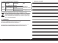
BUILDING PRECAUTIONS
During assembly, we recommend resting the parts on a
soft surface such as a soft towel to help prevent denting
the sheeting.
REMOVING WRINKLES
The covering of your model may develop wrinkles during
shipping and will require the use of a heat gun (HAN100)
and covering glove (HAN150) or covering iron (HAN101)
with a sealing iron sock (HAN141) to remove them. Use
caution while working around areas where the colors
overlap to prevent separating the colors. Avoid using
too much heat, which could separate the colors. Placing
a cool damp cloth on adjacent colors will also help in
preventing the separation of the colors while removing
wrinkles.
FLUORESCENT COVERING PRECAUTION
The fl uorescent covering used on your model can
fade with exposure to direct sunlight over time. We
recommend keeping your model out of direct sunlight for
prolonged periods if possible.
TRANSPORTATION AND STORAGE
When transporting and storing your model, you will
need a minimum of 80 inches (2m) in length, and 18
inches (46cm) in height to accommodate the size of the
fuselage. We also recommend the use of a wing bag
and stabilizer bags to help protect these surfaces during
transport and storage. The control horns and linkages can
also cause damage to nearby surfaces even when placed
in storage bags. Always place surfaces so the tops are
together to prevent damage from the control horns and
linkages.
HINWEISE ZUM BAU
Während des Zusammenbaus empfehlen wird, dass die
Teile auf einer weichen Oberfl äche, wie einem Handtuch,
abgelegt werden, um ein Eindrücken der Bleche zu
verhindern.
ENTFERNEN VON FALTEN
Während des Transportes können bei der Bespannung
Falten aufgetreten sein. Sie können diese mit dem
Heißluftfön (HAN100) und Bespannhandschuh (HAN150)
oder dem Bügeleisenbezug (HAN141) entfernen. Bitte
achten Sie bei überlappenden Farben diese nicht durch
zuviel Hitze zu lösen. Ein kühlendes Stück Stoff kann hier
neben den Falten aufgelegt helfen, dass die Farben sich
nicht trennen.
VORSICHTSMASSNAHMEN BEI DER
FLUORESZIERENDEN ABDECKUNG
Die auf dem Modell verwendete fl uoreszierende
Abdeckung kann bei direkter Sonneneinstrahlung im
Laufe der Zeit verblassen. Wir empfehlen, das Modell
über längere Zeiträume möglichst keinem direkten
Sonnenlicht auszusetzen.
TRANSPORT UND LAGERUNG
Bei dem Transport des Modells benötigen Sie mindestens
2 Meter Länge und 46cm Höhe für den Rumpf. Wir
empfehlen ebenfalls Flächen- und Leitwerkstaschen um
Transportschäden zu vermeiden. Durch die Ruderhörner
können ebenfalls Flächen beschädigt werden, so dass
diese nur mit den Oberseiten zueinander gelagert werden
sollten.
MONTAGE DER OPTIONALEN
SCHWIMMER
Bei der Montage der empfohlenen Schwimmer auf
dem Ultra Stick 10cc sicherstellen, die unter Optionale
Schwimmer aufgeführten Teile zu verwenden.
EMPFOHLENE SERVOS UND
GESCHWINDIGKEITSREGLER
Bei der Verwendung der empfohlenen Servos und
Geschwindigkeitsregler funktionieren die Servos
möglicherweise etwas langsamer als erwartet. Dies
wurde vollständig getestet und das Modell wird mit dieser
Kombination perfekt funktionieren. Zum Erreichen einer
optimalen Leistung der Servos kann das im Empfänger
eingesteckte rote Kabel vom Geschwindigkeitsregler
entfernt und ein separater Empfänger-Akku verwendet
werden, laut der Empfehlung der aufgeführten Teile für
den 2-Takt-Benziner.
KOMBINATIONEN AUS MOTOR, AKKU
UND PROPELLER
Wir haben eine Vielzahl von Kombinationen aus Motor,
Akku und Propeller getestet. Das Nachfolgende ist das
Ergebnis dieser Tests.
• Bei der Verwendung von Power 52 Motor, 5S 5000mA
Akku und 14 x 8,5E APC Propeller empfehlen
wir mindestens die Verwendung eines 60A
Geschwindigkeitsreglers (ELFA1060B).
• Bei der Verwendung von Power 52 Motor, 6S
5000mA Akku und 14 x 6E APC Propeller empfehlen
wir mindestens die Verwendung eines 80A
Geschwindigkeitsreglers (EFLA1080B).
• Bei der Verwendung von Power 52 Motor, 5S
5000mA Akku und 15 x 8E APC Propeller empfehlen
wir mindestens die Verwendung eines 60A
Geschwindigkeitsreglers (EFLA1060B).
OPTIONAL FLOAT INSTALLATION
When installing the recommended fl oats on your Ultra
Stick 10cc, make sure to use the parts listed under the
Optional Floats parts.
RECOMMENDED SERVOS AND ESC
When using the recommended servos and ESC, the
servos may appear to operate slightly slower than
expected. This has been fully tested, and your model will
operate perfectly with this combination. To achieve the
optimum performance from the servos, you can remove
the red wire from the ESC that plugs into the receiver, and
use a separate receiver battery as recommended in the
2-stroke gas parts listing.
MOTOR, BATTERY AND PROPELLER
COMBINATIONS
We have tested a variety of motor, battery and propeller
combinations. The following are the results of this testing.
• When using a Power 52 motor, 5S 5000mAh battery
and 14 x 8.5E APC propeller, we recommend using a
minimum of a 60A ESC (ELFA1060B).
• When using a Power 52 motor, 6S 5000mAh battery
and 14 x 6E APC propeller, we recommend using a
minimum of a 80A ESC (EFLA1080B).
• When using a Power 52 motor, 5S 5000mAh battery
and 15 x 8E APC propeller, we recommend using a
minimum of a 60A ESC (EFLA1060B).

11
Ultra Stick
™
10cc
PRÉCAUTIONS D’ASSEMBLAGE
Lors de l’assemblage de votre modèle, nous vous
recommandons de poser les pièces sur une surface
douce comme une serviette douce pour éviter d’abîmer
l’entoilage.
ÉLIMINATION DES PLIS
L’entoilage de votre modèle peut développer des plis
lors de l’expédition. Vous pouvez les lisser en utilisant le
pistolet à air chaud (HAN100) et le gant (HAN150) ou le
fer à entoiler (HAN101) avec la chaussette de protection
(HAN141). Soyez vigilant sur les zones où plusieurs
couleurs d’entoilage sont superposées, une température
trop élevée pourrait séparer les couleurs. Placez un
chiffon humide et froid sur les couleurs adjacentes pour
éviter leur séparation lorsque vous enlevez les plis.
PRÉCAUTIONS EN MATIÈRE
D’ENTOILAGE FLUORESCENT
L’entoilage fl uorescent utilisé sur votre modèle peut
décolorer avec le temps en cas d’exposition directe
au soleil. Si possible, nous vous recommandons de
conserver votre modèle à l’abri du soleil pendant les
périodes prolongées.
TRANSPORT ET STOCKAGE
Lorsque vous transportez ou stockez votre modèle, il
vous faudra un espace d’au moins 2m de longueur et
46cm de hauteur pour accueillir le fuselage. Nous vous
recommandons également l’utilisation d’un sac pour ailes
et de sacs pour stabilisateurs pour les protéger lors du
transport ou stockage. Les guignols et tringleries peuvent
également endommager les gouvernes même dans
les sacs de stockage. Placez toujours les gouvernes de
façon à ce que les parties supérieures soient l’une contre
l’autre pour éviter les contacts et dommages causés par
les guignols ou tringleries.
INSTALLATION DES FLOTTEURS
FACULTATIFS
Lors de l’installation des fl otteurs recommandés sur
votre UltraStick10cc, assurez-vous d’utiliser les pièces
répertoriées dans la partie Pièces des fl otteurs facultatifs.
SERVOS ET VARIATEURS ESC
RECOMMANDÉS
Lors de l’utilisation des servos et variateurs ESC
recommandés, les servo peuvent sembler fonctionner
plus lentement que prévu. Tout a été entièrement testé
et votre modèle fonctionnera parfaitement avec cette
combinaison. Pour atteindre les performances optimales
des servos, vous pouvez retirer le fi l rouge du variateur
ESC qui se branche au récepteur, puis utiliser une batterie
de récepteur séparée comme recommandé dans la liste
des pièces à essence deux temps.
COMBINAISONS MOTEUR, BATTERIE ET
HÉLICE
Nous avons testé plusieurs combinaisons de moteur,
batterie et hélice. Vous trouverez ci-dessous les résultats
de ces tests.
• Avec un moteur Power52, une batterie 5S 5000mAh
et une hélice APC 14 x 8,5E, nous recommandons
d’utiliser au minimum un variateur ESC 60A
(ELFA1060B).
• Avec un moteur Power52, une batterie 6S 5000mAh
et une hélice APC 14 x 6E, nous recommandons
d’utiliser au minimum un variateur ESC 80A
(EFLA1080B).
• Avec un moteur Power52, une batterie 5S 5000mAh
et une hélice APC 15 x 8E, nous recommandons
d’utiliser au minimum un variateur ESC 60A
(EFLA1060B).
PRECAUZIONI PER LA COSTRUZIONE
Durante l’assemblaggio noi consigliamo di appoggiare
le varie parti su di una superfi cie morbida come un
asciugamano di spugna per evitare ammaccature al
rivestimento.
TOGLIERE LE GRINZE
rivestimento di questo modello potrebbe sviluppare delle
grinze durante la spedizione e quindi per toglierle, sarà
necessario usare una pistola termica (phon) (HAN100) e
un guanto speciale (HAN150), oppure un ferro apposito
per rivestimenti (HAN101) con la sua calza (HAN141).
Bisogna usare cautela quando si lavora attorno ad
aeree con sovrapposizione di colori per evitare la loro
separazione. Evitare di scaldare troppo per non separare
i colori. Mettere un panno umido fresco sui colori vicini,
aiuta a prevenire la separazione dei colori mentre si
tolgono le grinze.
PRECAUZIONI PER IL RIVESTIMENTO
FLUORESCENTE
Con il tempo, il rivestimento fl uorescente utilizzato sul
modello può sbiadire se esposto direttamente alla luce
solare. Se possibile, si raccomanda di non tenere il
modello alla luce diretta del sole per lunghi periodi.
TRASPORTO E DEPOSITO
Quando si trasporta o si tiene in magazzino questo
modello, sarà necessario uno spazio di 2 metri di
lunghezza e di 46 centimetri in altezza per adattarsi alle
dimensioni della fusoliera. Si consiglia anche di usare
una custodia per proteggere le ali e lo stabilizzatore. Le
squadrette e i rinvii possono pure causare danni alle
superfi ci vicine anche se sono sistemate dentro alle
custodie. Per evitare questo, sistemare le superfi ci in
modo da mettere a contatto le loro parti superiori che non
hanno squadrette o rinvii.
INSTALLAZIONE DEL GALLEGGIANTE
OPZIONALE
Se si installano i galleggianti raccomandati su Ultra Stick
10cc, assicurarsi di utilizzare i componenti elencati nella
tabella relativa ai Galleggianti opzionali.
SERVO E ESC RACCOMANDATI
Utilizzando i servo e l’ESC raccomandati, la velocità di
funzionamento dei servo potrebbe sembrare inferiore
alle aspettative. I componenti sono stati sottoposti a
test approfonditi e il modello funzionerà perfettamente
con tale combinazione. Per ottenere prestazioni ottimali
dai servo, è possibile rimuovere il cavetto rosso che
collega l’ESC al ricevitore e usare una batteria separata
per il ricevitore come quella consigliata nell’elenco dei
componenti relativi al 2-tempi a benzina.
COMBINAZIONI MOTORE, BATTERIA ED
ELICA
Sono stati eseguiti test su diverse combinazioni di
motore, batteria ed elica. I risultati dei test sono i
seguenti.
• Se si utilizza un motore Power 52, batteria 5S
5000mAh ed elica APC 14 x 8,5E, si raccomanda l’uso
minimo di un ESC 60A (ELFA1060B).
• Se si utilizza un motore Power 52, batteria 6S
5000mAh ed elica APC 14 x 6E, si raccomanda l’uso
minimo di un ESC 80A (EFLA1080B).
• Se si utilizza un motore Power 52, batteria 5S
5000mAh ed elica APC 15 x 8E, si raccomanda l’uso
minimo di un ESC 60A (EFLA1060B).

12EN
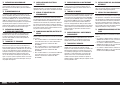
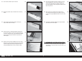
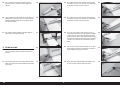
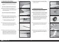
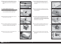
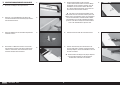
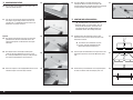
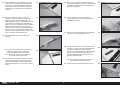
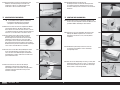
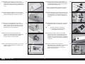
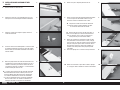
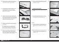
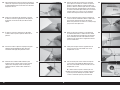
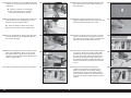
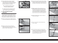
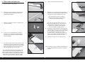
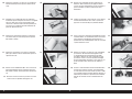
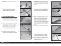
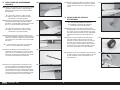
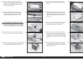
AILERON AND FLAP INSTALLATION
1. Remove the aileron and fl ap from the wing.
1.
2.
3.
4.
5.
2. Use a 5/64-inch (2mm) drill bit to clear the holes of any
debris for the control horn mounting screws.
3. Use a hobby knife to separate the control horn backplate
from the control horn.
4. Insert the three M2 x 25 machine screws into the holes
of the control horn, then into the holes in the aileron.
Make sure the control horn is installed on the bottom of
the aileron.
5. Slide the control horn backplate on the screws. Apply
a small amount of canopy glue on the screws using a
toothpick, then thread the M2 nuts on the screws. Use
a #1 Phillips screwdriver and 4mm nut driver to tighten
the screws.
The holes in the control horn backplate are sized
to allow the screw to pass through them. The nuts
must be used to properly secure the control horns
to the control surface. Failure to secure the control
horns with the included nuts will result in the control
horns not being secure on the control surface.
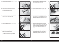
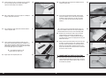
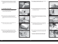
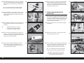
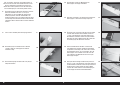
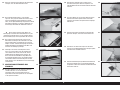
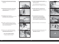
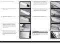
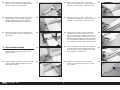
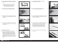
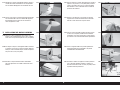
6.
7.
8.
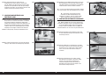
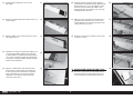
6. Use side cutters to trim the screws.
7. Use a fi le to lightly fi le any sharp points from the screws
after they have been trimmed. Use care not to contact
the control surface with the fi le.
Prepare and install the flap control horns at this time
following the same procedure as the aileron control horns.
Make sure to drill the hole for the hinges.
The hole provides a tunnel for the CA to fully
wick into the hinge. Not drilling this hole may
result in hinges that are not properly glued.
8. Remove the hinges from the aileron and fl ap. Use a pin
vise and 1/16-inch (1.5mm) drill bit to drill a hole in the
center of each hinge slot to allow the CA to wick into the
hinge. Drill holes in both the wing and control surfaces
at this time. The ailerons and fl aps can both be prepared
during this step.
9. Place a T-pin in the center of each hinge.
10. Slide the hinges into position in the aileron with the T-pin
resting against the edge of the control surface.
9.
10.

13 EN
Ultra Stick
™
10cc
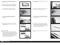
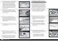
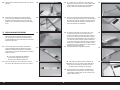
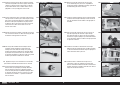
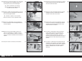
11.
12.
13.
14.
15.
16.
17.
18.
19.
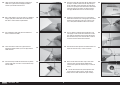
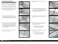
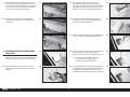
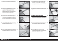
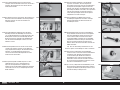
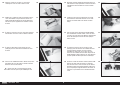
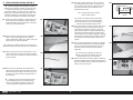
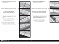
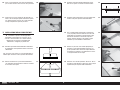
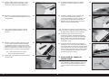
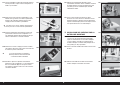
11. Install all three aileron hinges at this time. 16. Check the gap between the fl ap and aileron. Use a thin
ruler (or similar) that is 1/16-inch (1.5mm) thick as a
spacer so the gap between the ailerons and fl aps are
the same. Remove the T-pins and glue the hinges for the
fl aps using thin CA.
12. Repeat the previous steps to install all three of the fl ap
hinges.
17. Once the CA cures, gently pull on the fi xed surface
and control surface to make sure the hinges are glued
securely. If not, apply additional CA to secure each of the
hinges.
13. Fit the aileron and fl ap to the wing by inserting the
hinges into the slots in the wing.
18. Flex the fl ap and aileron through their range of motion a
few times to break in the hinges.
14. Check that there is a slight gap between the wing and
the end of the aileron. Use a thin ruler (or similar) that is
1/16-inch (1.5mm) thick as a spacer so both the ailerons
have the same size gap. Remove the T-pins from the
aileron hinges.
15. Apply thin CA to the top and bottom of each hinge. Once
the CA cures, gently pull on the fi xed surface and control
surface to make sure the hinges are glued securely. If
not, apply additional CA to secure each of the hinges.
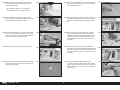
AILERON AND FLAP SERVO INSTALLATION
19. Remove the aileron servo hatch from the wing. Make
sure to keep the string taped to the wing so it doesn’t fall
into the wing.

14EN
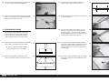
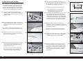
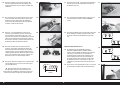
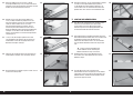
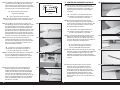
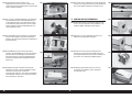
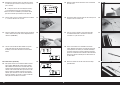
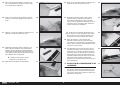
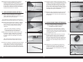
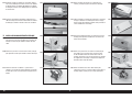
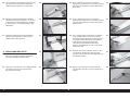
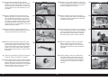
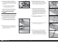
20.
21.
22.
23.
24.
25.
26.
27.
28.
29.
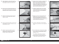
20. Use a hobby knife and #11 blade to remove the covering
in the servo cover to the servo arm.
25. Apply a small amount of thin CA to harden the threads
made in the previous step. Allow the CA to fully cure
before installing the aileron servo cover.
22. Use a toothpick to puncture the covering to locate the
holes for the aileron and fl ap cover screws.
27. Fit the servo between the servo mounting tabs in the
aileron servo tray. The servo arm will be centered in the
slot. Mark the locations for the servo mounting screws
using a pencil, then remove the servo.
21. Check that the servo mount is glued securely to the
servo cover. If the mount is not secure, use a small
amount of medium CA or epoxy to make sure the mount
is securely fastened to the servo cover.
26. Install the grommets and eyelets in the servos. Follow
any instructions included with the servo. Prepare both
fl ap and aileron servos at this time.
23. Use a pin vise and 5/64-inch (2mm) drill bit to drill the
holes in the servo cover mounts.
24. Thread an M3 x 10 self-tapping screw into each of the
holes in the aileron and fl ap servo cover mounting holes.
Remove the screws before proceeding.
Make sure not to apply excessive downward
pressure which could result in damage to the wing.
28. Use a drill and a 5/64-inch (2mm) drill bit to drill the
holes for the servo mounting screws in the locations
marked in the previous step. Use a 2mm hex wrench to
thread a servo mounting screw into each of the holes in
the aileron servo mounting holes. Remove the screws,
then apply a small amount of thin CA to harden the
threads.
29. Center the aileron servos using the radio system. Prepare
both aileron servos at this time. The output of the servo
arms will mirror each other so the ailerons work in
opposite directions. Use side cutters to remove any
unused arm so they don’t interfere with the operation of
the servo.

15 EN
Ultra Stick
™
10cc
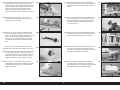
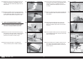
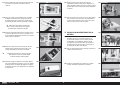
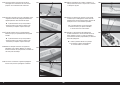
35.
36.
37.
38.
39.
30.
5/8 inch
(16mm)
31.
32.
33.
34.
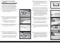
30. Enlarge the hole in the servo arm that is 5/8-inch
(16mm) from the center of the servo. (Drawing is not to
scale).
The servo arm length listed is suited for sport flying.
Longer servo arms, such as those included with DUB671,
can be used for more extreme throws and 3D flight.
31. Secure the servo to the cover using a #1 Phillips
screwdriver and the screws provided with the servo.
32. Secure an 9-inch (230mm) servo extension to the
tip servo using a commercially available retainer
(SPMA3054).
33. When building your model with four wing servos (two
fl ap servos, two aileron servos), make sure to orient the
servos as shown.
Optional Two-Servo Wing
34. An optional set of ailerons can be purchased to build
your model without fl aps. When building the aileron-only
version, swap the aileron and fl ap servo covers in the left
wing panel. Use the inner positions for the aileron servos,
and secure the outer servo covers using the steps
outlined in this section of the manual. This allows the use
of a “Y” harness to operate the ailerons.
35. Tie or tape the string located inside the wing to the end
of the servo lead.
36. Retrieve the servo lead at the wing root. Guide the lead
through the hole in the bottom of the wing.
37. Secure the aileron cover in the wing using four M3 x 10
self-tapping screws. Use a #2 Phillips screwdriver to
tighten the screws.
38. Thread an M3 nut on one end of the 100mm pushrod.
Slide a clevis retainer (silicone tubing) on a metal clevis,
then thread the clevis on the rod. Repeat so there are
clevises on both ends of the pushrod. Make the pushrods
for both ailerons and fl aps at this time.
39. Attach the clevis to the hole of the servo arm enlarged
earlier.

16EN
40.
41.
42.
43.
5/8 inch
(16mm)
44.
45.
46.
47.
48.
49.
40. Connect the clevis to the center hole of the control horn.
With the radio on and aileron servo centered, adjust the
link to center the aileron.
41. Once set, slide the clevis retainer (silicone tubing) over
the forks of the clevises, then tighten the nuts against
the clevises. Use threadlock on the nuts to prevent them
from vibrating loose.
42. Center the fl ap servos using the radio system. Prepare
both fl ap servos at this time. The output of the servo
arms will be identical so the fl aps work in the same
directions. Use side cutters to remove any unused arm so
they don’t interfere with the operation of the servo.
43. Enlarge the hole in the servo arm that is 5/8-inch
(16mm) from the center of the servo. (Drawing is not to
scale).
The servo arm length listed is suited for sport flying.
Longer servo arms, such as those included with DUB671,
can be used for more extreme throws and 3D flight.
44. Install the fl ap servo and assemble the linkage for the
fl ap using the same technique as the aileron linkage. Use
the radio system to set the fl ap to the up position. Adjust
the link so the fl ap is in the up fl ap position.
45. Use the radio system to set the fl ap to the down position.
Use the radio to set the full defl ection position.
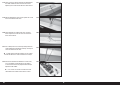
WING INSTALLATION
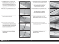
46. Fit the dowels on the leading edge of the wing into the
holes in the fuselage.
47. Place the wing bolt plate on the wing, then thread the
1/4-20 x 1
3
/
4
-inch nylon wing bolts into the blind nuts in
the fuselage to secure the wing.
Optional
48. The wing bolt plate can be glued directly to the wing.
Use a felt-tipped pen to trace the outline of the wing bolt
plate on the top of the wing.
49. Remove the wing bolts and wing bolt plate. Use a hobby
knife with a new #11 blade to remove the covering 3/32-
inch (2mm) inside the lines drawn on the wing.

17 EN
Ultra Stick
™
10cc
54.
55.
56.
57.
58.
50.
51.
50. Use a paper towel and isopropyl alcohol to remove the
lines from the wing made by the felt-tipped pen.
51. Brush a small amount of 5-minute epoxy on the exposed
wood. Place the wing bolt plate in position and allow the
epoxy to fully cure before proceeding.
STABILIZER INSTALLATION
Check the stabilizer mounting surface on the
fuselage to make sure it is flush with the fuselage
sides. If the fuselage sides protrude beyond the
stabilizer mounting surface, then sand them flush.
53. Measure from the tip of the stabilizer to the wing.
Position the stabilizer so both measurements are equal.
54. Check the alignment of the stabilizer to the wing. It
should be equal on both sides of the fuselage.
55. Check all alignments. Mark the outline of the fuselage on
the top of the stabilizer.
56. Use a ruler and carefully cut the covering 1/8 inch (3
mm) inside the line drawn on the stabilizer to remove
the covering from the center of the stabilizer. Remove
the top and bottom covering. Use care not to cut into the
underlying wood, weakening the stabilizer.
57. Use a paper towel and isopropyl alcohol to remove the
lines from the stabilizer. Apply a small amount of thin CA
along the edge of the covering to strengthen the area
under the covering in case the knife has penetrated to
underlying wood.
58. Mix 1/2 ounce (15ml) of 30-minute epoxy. Use an epoxy
brush to apply epoxy to the exposed wood on the top of
the stabilizer.
52. Remove the elevators from the stabilizer. Fit the stabilizer
into the notch in the fuselage. Center the stabilizer.
Make sure to slide the stabilizer forward
so the elevator joiner wire can be installed.
52.
53.

18EN
59.
60.
61.
62.
63.
64.
65.
66.
67.
68.
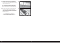
59. Use an epoxy brush to apply epoxy to the stabilizer
mounting surface in the notch in the fuselage for the
stabilizer.
60. Fit the stabilizer back into position. Check the alignment
following steps 1 through 3, then use a paper towel and
isopropyl alcohol to remove any excess epoxy from the
fuselage and stabilizer.
61. Use clamps to hold the stabilizer in position. Allow the
epoxy to fully cure before proceeding.
FIN INSTALLATION
62. Fit the fi n into the slot in the fuselage. Use a ruler to
check the alignment of the fi n to the rear edge of the
fuselage.
63. Use a felt-tipped pen to trace the outline of the fi n on the
top of the fuselage. Also mark the bottom of the fi n along
the fuselage.
64. Use a hobby knife with a #11 blade to carefully remove
the covering 1/8-inch (3mm) inside the lines drawn from
the top of the fuselage at the rear of the fi n.
65. Use a hobby knife with a #11 blade to carefully remove
the covering 1/8-inch (3mm) inside the lines drawn from
the top of the fuselage at the front of the fi n.
66. Use a ruler and carefully cut the covering 1/8 inch (3
mm) below the line drawn on the fi n. Remove the bottom
covering. Use care not to cut into the underlying wood,
weakening the fi n. Apply a small amount of thin CA along
the edge of the covering to strengthen the area under the
covering in case the knife has penetrated to underlying
wood.
67. Mix 1/2 ounce (15ml) of 30-minute epoxy. Use an epoxy
brush to apply the epoxy in the slot for the fi n and to the
exposed wood on the top of the fuselage.
68. Apply epoxy to the exposed wood on the bottom of the
fi n where it comes in contact with the fuselage.

19 EN
Ultra Stick
™
10cc
69.
70.
71.
72.
73.
74.
75.
76.
77.
78.
69. Fit the fi n in position. Check that it is square to the
fuselage.
70. Use tape to hold the fi n in position until the epoxy fully
cures. Check the position of the fi n to make sure it is still
square to the stabilizer while the epoxy is curing.
ELEVATOR INSTALLATION
71. Remove the elevator joiner wire from the elevators.
Lightly sand the elevator joiner wire where it contacts
the elevators. Use a paper towel and isopropyl alcohol to
remove any oil or debris from the joiner.
72. Fit the joiner wire into the elevator halves. The elevator
joiner wire must be fl ush with the leading edge of the
elevator as shown. Check to make sure the elevator
halves are in alignment with each other.
Poorly aligned elevators will cause problems
with trimming your model in flight.
73. Place the elevators on a fl at surface. Make sure both
elevators lay fl at on the surface.
74. If the elevators are not in alignment, use pliers to bend
the joiner wire slightly to bring the halves into alignment.
Continue the assembly of your model once the joiner
wire has been correctly checked and adjusted.
75. Use low-tack tape to secure a 2-inch (50mm) wide piece
of clear plastic or waxed paper around the stabilizer
against the fuselage. This will prevent accidentally gluing
the joiner wire and elevators to the stabilizer.
76. Use a pin vise and 1/16-inch (1.5mm) drill bit to drill a
hole in the center of each hinge slot to allow the CA to
wick into the hinge. Drill holes in both the elevators and
stabilizer surfaces at this time. Place a T-pin in the center
of each hinge along side the slot in the hinge. This will
help center the hinge when it is placed in the elevators.
Slide the hinges into position with the T-pin resting
against the edge of the control surface.
77. Partially install the joiner wire into the elevator.
Fitting the elevator to the stabilizer will require
you to be quick as not to allow the epoxy to cure
that secures the joiner wire. Read through and
practice these steps before mixing any epoxy.
78. Test fi t the elevator to the stabilizer by sliding the hinges
into the slots. The joiner wire will be installed in position
while the hinges are being inserted into the slots.

20EN
84.
85.
86.
87.
88.
79.
80.
81.
82.
83.
79. Check to make sure you can install the hinges and joiner
wire. The leading edge of the elevator will fi t tightly
against the trailing edge of the stabilizer.
80. Mix a small amount of 15-minute epoxy. Use a toothpick
to apply epoxy to the joiner wire.
81. Use a toothpick to apply epoxy to the stabilizer where it
contacts the joiner wire.
82. Fit the elevator back into position. Remove the T-pins
and slide the elevator tightly against the stabilizer. Use a
paper towel and isopropyl alcohol to remove any excess
epoxy before it begins to cure. Use low-tack tape to hold
the elevator tightly against the stabilizer.
The remaining elevator can be
installed while the epoxy cures.
84. Use a toothpick to apply epoxy to the stabilizer where it
contacts the joiner wire.
85. Fit the remaining elevator into position. Slide it tightly
against the stabilizer, then use low-tack tape to hold it
in position until the epoxy fully cures. Once the epoxy
has cured, remove all tape and clear plastic from the
stabilizer.
Do not use CA accelerator when gluing hinges. The
CA must be allowed to soak into each hinge to provide the
greatest bond between the hinges and surrounding wood.
86. Remove the T-pins from the hinges. Flex the elevator
slightly, making sure to keep the gap between the
elevator and stabilizer as narrow as possible. Saturate
each of the hinges using thin CA. Apply CA to the top and
bottom of the hinges.
87. Gently pull on the fi xed and moving surface to make sure
the hinges are glued securely. If not, reapply thin CA to
any hinges that are found loose. Flex the control surface
through its range of motion a few times to break-in the
hinges. This will reduce the initial load on the servo when
the surface is fi rst actuated.
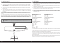
RUDDER AND TAIL WHEEL INSTALLATION
88. Slide the tail wheel bracket on the tail wheel wire. Use a
1.5mm hex wrench to loosen the setscrews in the wheel
collar for the tail wheel. Slide the wheel collar as close to
the tail wheel as possible.
83. Apply epoxy to the exposed joiner wire.
La pagina si sta caricando...
La pagina si sta caricando...
La pagina si sta caricando...
La pagina si sta caricando...
La pagina si sta caricando...
La pagina si sta caricando...
La pagina si sta caricando...
La pagina si sta caricando...
La pagina si sta caricando...
La pagina si sta caricando...
La pagina si sta caricando...
La pagina si sta caricando...
La pagina si sta caricando...
La pagina si sta caricando...
La pagina si sta caricando...
La pagina si sta caricando...
La pagina si sta caricando...
La pagina si sta caricando...
La pagina si sta caricando...
La pagina si sta caricando...
La pagina si sta caricando...
La pagina si sta caricando...
La pagina si sta caricando...
La pagina si sta caricando...
La pagina si sta caricando...
La pagina si sta caricando...
La pagina si sta caricando...
La pagina si sta caricando...
La pagina si sta caricando...
La pagina si sta caricando...
La pagina si sta caricando...
La pagina si sta caricando...
La pagina si sta caricando...
La pagina si sta caricando...
La pagina si sta caricando...
La pagina si sta caricando...
La pagina si sta caricando...
La pagina si sta caricando...
La pagina si sta caricando...
La pagina si sta caricando...
La pagina si sta caricando...
La pagina si sta caricando...
La pagina si sta caricando...
La pagina si sta caricando...
La pagina si sta caricando...
La pagina si sta caricando...
La pagina si sta caricando...
La pagina si sta caricando...
La pagina si sta caricando...
La pagina si sta caricando...
La pagina si sta caricando...
La pagina si sta caricando...
La pagina si sta caricando...
La pagina si sta caricando...
La pagina si sta caricando...
La pagina si sta caricando...
La pagina si sta caricando...
La pagina si sta caricando...
La pagina si sta caricando...
La pagina si sta caricando...
La pagina si sta caricando...
La pagina si sta caricando...
La pagina si sta caricando...
La pagina si sta caricando...
La pagina si sta caricando...
La pagina si sta caricando...
La pagina si sta caricando...
La pagina si sta caricando...
La pagina si sta caricando...
La pagina si sta caricando...
La pagina si sta caricando...
La pagina si sta caricando...
La pagina si sta caricando...
La pagina si sta caricando...
La pagina si sta caricando...
La pagina si sta caricando...
La pagina si sta caricando...
La pagina si sta caricando...
La pagina si sta caricando...
La pagina si sta caricando...
La pagina si sta caricando...
La pagina si sta caricando...
La pagina si sta caricando...
La pagina si sta caricando...
La pagina si sta caricando...
La pagina si sta caricando...
La pagina si sta caricando...
La pagina si sta caricando...
-
 1
1
-
 2
2
-
 3
3
-
 4
4
-
 5
5
-
 6
6
-
 7
7
-
 8
8
-
 9
9
-
 10
10
-
 11
11
-
 12
12
-
 13
13
-
 14
14
-
 15
15
-
 16
16
-
 17
17
-
 18
18
-
 19
19
-
 20
20
-
 21
21
-
 22
22
-
 23
23
-
 24
24
-
 25
25
-
 26
26
-
 27
27
-
 28
28
-
 29
29
-
 30
30
-
 31
31
-
 32
32
-
 33
33
-
 34
34
-
 35
35
-
 36
36
-
 37
37
-
 38
38
-
 39
39
-
 40
40
-
 41
41
-
 42
42
-
 43
43
-
 44
44
-
 45
45
-
 46
46
-
 47
47
-
 48
48
-
 49
49
-
 50
50
-
 51
51
-
 52
52
-
 53
53
-
 54
54
-
 55
55
-
 56
56
-
 57
57
-
 58
58
-
 59
59
-
 60
60
-
 61
61
-
 62
62
-
 63
63
-
 64
64
-
 65
65
-
 66
66
-
 67
67
-
 68
68
-
 69
69
-
 70
70
-
 71
71
-
 72
72
-
 73
73
-
 74
74
-
 75
75
-
 76
76
-
 77
77
-
 78
78
-
 79
79
-
 80
80
-
 81
81
-
 82
82
-
 83
83
-
 84
84
-
 85
85
-
 86
86
-
 87
87
-
 88
88
-
 89
89
-
 90
90
-
 91
91
-
 92
92
-
 93
93
-
 94
94
-
 95
95
-
 96
96
-
 97
97
-
 98
98
-
 99
99
-
 100
100
-
 101
101
-
 102
102
-
 103
103
-
 104
104
-
 105
105
-
 106
106
-
 107
107
-
 108
108


Hangar 9 HAN2345 Manuale del proprietario
- Categoria
- Giocattoli telecomandati
- Tipo
- Manuale del proprietario
- Questo manuale è adatto anche per
in altre lingue
- English: Hangar 9 HAN2345 Owner's manual
- français: Hangar 9 HAN2345 Le manuel du propriétaire
- Deutsch: Hangar 9 HAN2345 Bedienungsanleitung
Documenti correlati
-
 Hangar 9 HAN5280 Manuale del proprietario
-
 Hangar 9 HAN5080 Manuale del proprietario
-
 Hangar 9 HAN6030 Manuale del proprietario
-
 Hangar 9 HAN2370 Manuale del proprietario
-
 Hangar 9 HAN5080 Guida d'installazione
-
 Hangar 9 P-47D-1 Thunderbolt 60 Manuale utente
-
 Hangar 9 HAN5260 Manuale del proprietario
-
 Hangar 9 HAN4770 Manuale del proprietario
-
 Hangar 9 HAN2990 Manuale del proprietario
-
 Hangar 9 HAN4770 Manuale del proprietario


Altri documenti
-
E-flite EFLUA1190 Manuale del proprietario
-
E-flite P-51D Mustang Manuale utente
-
arf EFL2790 Manuale del proprietario
-
E-flite EFL1045016 Manuale utente
-
E-flite J-3 Cub 450 Manuale utente
-
 HYPE 018-1560 Manuale utente
-
-
E-flite EFLA550 Manuale del proprietario
-
Evolution EVOE10GX Manuale utente
-
