Allied Telesis AR400 series Installation And Safety Manual
- Categoria
- Switch di rete
- Tipo
- Installation And Safety Manual

A5 Installation and Safety Guide Cover
AR400 Series Router
AR415S
AR440S
AR441S
AR442S
AR450S
Installation and Safety Guide

2 AR400 Series Router
613-000313 Rev C
AR400 Series Installation and Safety Guide
Document Number 613-000313 Rev C.
Copyright © 2004-2006 Allied Telesis Inc. All rights reserved. No part of this
publication may be reproduced without prior written permission from Allied
Te les i s, I n c .
Allied Telesis, Inc. reserves the right to make changes in specifications and other
information contained in this document without prior written notice. The
information provided herein is subject to change without notice. In no event
shall Allied Telesis, Inc. be liable for any incidental, special, indirect, or
consequential damages whatsoever, including but not limited to lost profits,
arising out of or related to this manual or the information contained herein,
even if Allied Telesis has been advised of, known, or should have known, the
possibility of such damages.
All company names, logos, and product designs that are trademarks or
registered trademarks are the property of their respective owners.

Installation and Safety Guide 3
613-000313 Rev C
Table of Contents
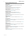
Electrical Safety Statements ................................................................................................... 4
Models Covered By This Guide ........................................................................................... 5
Package Contents .................................................................................................................... 5
AR450S Routers ...................................................................................................................... 7
Installing the AR450S .......................................................................................................7
Configuring the AR450S .................................................................................................9
Connecting Data Cables to the AR450S ................................................................. 13
System LEDs on the AR450S ...................................................................................... 14
AR415S Router ...................................................................................................................... 15
Installing the AR415S .................................................................................................... 15
Configuring the AR415S .............................................................................................. 18
Connecting Data Cables to AR415S ......................................................................... 23
System LEDs on AR415S ............................................................................................. 24
AR440S, AR441S, AR442S Routers .................................................................................. 25
Installing the AR440S, AR441S, AR442S .................................................................. 25
Configuring the AR440S, AR441S, AR442S ............................................................ 29
Connecting Data Cables to AR440S, AR441S, AR442S ....................................... 35
System LEDs on AR440S, AR441S, AR442S ........................................................... 36
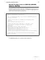
Default Configuration on AR415S, AR440S, AR441S, AR442S .................................. 37
Documentation and Tools CD-ROM ................................................................................ 38
Connection to mains voltage supply ................................................................................. 39
Telecommunications Interfaces .......................................................................................... 39
Safety ........................................................................................................................................ 41
Sicherheit ................................................................................................................................. 42
Sikkerhed ................................................................................................................................. 43
Veiligheid .................................................................................................................................. 44
Sécurité .................................................................................................................................... 45
Turvallisuus .............................................................................................................................. 46
Norme di Sicurezza ............................................................................................................... 47
Sikkerhet .................................................................................................................................. 48
Segurança ................................................................................................................................. 49
Seguridad ................................................................................................................................. 50
Säkerhet ................................................................................................................................... 51
US Federal Communications Commission (FCC) ......................................................... 52
Canadian Department of Communications ..................................................................... 53
Emission Compliance Statements ...................................................................................... 54
EC Declaration of Conformity ........................................................................................... 56

4 AR400 Series Router
613-000313 Rev C
Electrical Safety Statements
Electrical Safety
IMPORTANT: This equipment must be installed in accordance with safety
precautions (“Safety”, page 41).
Elektrische Sicherheit
WICHTIG: Für die Installation dieses Gerätes ist die Einhaltung von
Sicherheitsvorkehrungen erforderlich (“Sicherheit”, Seite 44).
Elektrisk sikkerhed
VIGTIGT: Dette udstyr skal installeres i overensstemmelse med
sikkerhedsadvarslerne (“Sikkerhed”, side 45).
Elektrische veiligheid
BELANGRIJK: Dit apparaat moet in overeenstemming met de
veiligheidsvoorschriften worden geïnstalleerd (“Veiligheid”, pagina 46).
Sécurité électrique
IMPORTANT: Cet équipement doit être utilisé conformément aux instructions de
sécurité (“Sécurité”, page 47) .
Sähköturvallisuus
TÄRKEÄÄ: Tämä laite on asennettava turvaohjeiden mukaisesti (“Turvallisuus”,
sivu 48).
Sicurezza elettrica
IMPORTANTE: questa apparecchiatura deve essere installata rispettando le norme
di sicurezza (“Norme di Sicurezza”, pagina 49).
Elektrisk sikkerhet
VIKTIG: Dette utstyret skal installeres i samsvar med sikkerhetsregler (“Sikkerhet”,
side 50).
Segurança eléctrica
IMPORTANTE: Este equipamento tem que ser instalado segundo as medidas de
precaução de segurança (“Segurança”, página 51).
Seguridad eléctrica
IMPORTANTE: La instalación de este equipo deberá llevarse a cabo cumpliendo con
las precauciones de seguridad (“Seguridad”, página 52).
Elsäkerhet
OBS! Alla nödvändiga försiktighetsåtgärder måste vidtas när denna utrustning
används (“Säkerhet”, sida 53).

Installation and Safety Guide 5
613-000313 Rev C
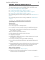
Models Covered By This Guide
This Installation and Safety Guide includes information on these models:
■ AR415S
■ AR440S
■ AR441S
■ AR442S
■ AR450S
You can download updates to this document from
www.alliedtelesis.com/support/software.
Package Contents
Before beginning any installation, please check the package contents. Contact your
authorised Allied Telesis distributor or reseller if any items are damaged or missing.
AR415S Package Contents:
■ one AR400 Series router
■ one AC power cord
■ one power cord retaining clip
■ one serial cable for connecting the router to a terminal or PC
■ two UTP network cables
■ one 19 inch rack-mount kit
■ one AR400 Series Router Installation and Safety Guide
■ one AR400 Series Router Documentation and Tools CD-ROM (includes the
complete AR400 Series Document Set and utilities)
■ one warranty card

6 AR400 Series Router
613-000313 Rev C
AR440S, AR441S and AR442S Package Contents:
■ one AR400 Series router
■ one AC power cord
■ one power cord retaining clip
■ one serial null modem cable for connecting the router to a terminal or PC
■ two UTP network cables
■ one DSL cable
AR440S: two in Australia and New Zealand
■ one 19 inch rack-mount kit
■ one AR400 Series Router Installation and Safety Guide
■ one AR400 Series Router Documentation and Tools CD-ROM (includes the complete
AR400 Series Document Set and utilities)
■ one warranty card
AR450S Package Contents:
■ one AR400 Series router
■ one AC power cord
■ one power cord retaining clip
■ one serial null modem cable for connecting the router to a terminal or PC
■ two UTP network cables
■ one 19 inch rack-mount kit
■ one AR400 Series Router Installation and Safety Guide
■ one AR400 Series Router Documentation and Tools CD-ROM (includes the complete
AR400 Series Document Set and utilities)
■ one warranty card
To install your router, see “AR450S Routers” following, “AR415S Router” on
page 15, or “AR440S, AR441S, AR442S Routers” on page 25.

Installation and Safety Guide 7
613-000313 Rev C
AR450S Router
This section describes how to install the AR450S router.
■ “Installing the AR450S” below
■ “Configuring the AR450S” on page 9
■ “Connecting Data Cables to the AR450S” on page 13
■ “System LEDs on the AR450S” on page 14
For corresponding information about installing an AR415S, see “AR415S Router” on
page 15.
For corresponding information about installing an AR440S, AR441S or AR442S, see
“AR440S, AR441S, AR442S Routers” on page 25.
Installing the AR450S
Selecting a Site
You can install the router:
■ on a level surface such as a desktop or bench
■ in a standard 19-inch rack, using the rack-mount kit supplied with the router
When you install the router, choose a site that:
■ allows adequate airflow around the router and its vents
■ is free of dust and moisture
■ will maintain ambient temperature in the range 0 ºC to 40 ºC (32 ºF to 104 ºF)
and humidity in the range 5% to 80% non-condensing
■ has a reliable and earthed (grounded) power supply, preferably dedicated and
filtered
■ does not expose cabling to sources of electrical noise such as radio transmitters,
broadband amplifiers, power lines, electric motors, and fluorescent fixtures
■ allows easy access to the router’s power and cable connections
Before Installing the Router
■ Read the safety information in “Safety” on page 41.
■ Unpack the router. Verify the package contents. If any items are damaged or
missing, contact your sales representative.

8 AR400 Series Router
613-000313 Rev C
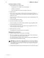
Installing the Router in a Rack
1. Gather additional items. You will need:
• the rack-mount kit included in the router package
• a Phillips #1 screwdriver
• screws and cage nuts to attach the brackets to your rack
2. Check the rack.
Ensure that the rack is safely secured and that it will not tip over. Devices in a
rack should be installed starting at the bottom, with the heavier devices near the
bottom of the rack.
Ensure the rack has sufficient space for the router and its associated cables. The
router is 1U high.
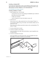
3. Unscrew the feet from the router.
4. Connect the handles to the brackets.
Screw the handles to the wider side of each bracket, using the supplied screws.
5. Connect the brackets to the router.
Screw the brackets to the sides of the router, using the supplied screws. The
router can be front or rear mounted.
6. Mount the router in the rack.
Use appropriate rack mounting screws (not supplied).
Applying Power to the Router
1. Check the supply voltage and the router’s rated voltage.
The router is fitted with a universal mains power supply that will function over
the range 100 VAC to 240 VAC and 50 Hz to 60 Hz.
For continued protection against the risk of fire and shock hazard, replace fuses
only with fuses of the same type and rating.
Warning The specific power supply requirements for a particular model are
clearly displayed on the rear or underside of the router. If the supply is outside
the accepted range for the router, the router may not operate or damage to
the router may result.
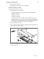
2. Fit the power cord retaining clip to the AC power inlet on the router’s rear panel.

Installation and Safety Guide 9
613-000313 Rev C
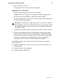
3. Connect the provided power cord to the AC power inlet and clip it in place.
Switch the router’s power switch to the ON position. The Power LED lights
continuously and the System LED lights briefly. The Port LEDs also light briefly.
The router is supplied with an approved power cord that incorporates a
moulded plug. It must only be used with the power cord supplied.
If the LEDs fail to light, the most likely cause is that the router is not receiving
power. Check that:
■ the power supply outlet’s switch (if any), and the router’s power switch, are in
the ON position
■ the power cable is securely plugged in
■ the power supply is operational
Configuring the AR450S
You can configure the router via the command line interface (CLI) or the graphical
user interface (GUI). First use the CLI to assign an IP address to the router, then use
the CLI or the GUI to complete the configuration.
■ “Using the CLI to configure the AR450S” below
■ “Using the GUI to configure the AR450S” on page 11
Using the CLI to configure the AR450S
This section describes how to access the router’s command line interface (CLI)
using a terminal or PC connected to the router’s console port.
1. Initiate router start-up.
Using the terminal cable supplied, connect a VT100-compatible terminal, or the
COM port of a PC running a terminal emulation program such as Windows
Hyper Terminal, to the Console RS-232 (ASYN0) port on the router’s rear
panel.
Set the communication parameters on your terminal or terminal emulation
program to:
• Baud rate: 9600
• Data bits: 8
•Parity: None
•Stop bits: 1
• Flow control: Hardware
See the AR400 Series Router Hardware Reference for more information on
configuring emulation software.

10 AR400 Series Router
613-000313 Rev C
2. Log in and set the password.
The login prompt appears on the terminal or PC. If the login prompt does not
appear, press [Enter] two or three times.
When the router boots for the first time it automatically creates an account
with manager privileges. The account has the user name “manager” and the
password is “friend”. Passwords are case sensitive.
At the login prompt, enter the user name and password.
Login: manager
Password: friend
The router’s command prompt appears and you can now configure the router
using the command line interface.
Warning Change the password as soon as possible. Leaving the manager
account with the default password is a serious security risk. Make sure you
remember the new password as there is no way to retrieve it if it is lost.
Use the following command to change the account password:
set password
3. Configure the router.
See the AR400 Series Router Software Reference for more information on router
start-up and configuration procedures (including a list of message definitions). To
continue configuring the router using the CLI, use the commands in the
Software Reference.
To display a list of help topics, enter:
help
To display help on a specific topic, enter:
help topic
Alternatively, type a question mark (?) at the end of a partially completed
command to see a list of valid options.
4. Save the configuration.
Save your configuration to a new file by using the command:
create config=filename.cfg
Then set the router to load this file when it restarts by using the command:
set config=filename.cfg
We recommend leaving the boot.cfg file unchanged, in case you need to revert
to the original default configuration.
To continue configuring the router using the GUI, see the following section.

Installation and Safety Guide 11
613-000313 Rev C
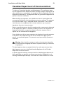
Using the GUI to configure the AR450S
This section describes how to access the GUI via a switch port in VLAN1 on the
AR450S router, when the PC and the router are in the same subnet, in order to
configure the router. The router’s switch ports all belong to VLAN1 by default.
The GUI requires a PC and web browser. Supported browsers are Internet Explorer
5.0 or later and Netscape 6.2.2 or later, with JavaScript enabled. If you are using a
toolbar or plug-in on your browser to block pop-ups, disable it while using the GUI.
The GUI displays detailed configuration options and information in pop-up windows.
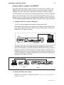
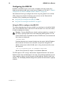
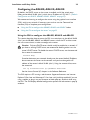
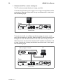
1. Connect the PC to a router switch port.
The PC can be connected either directly or through your LAN.
To connect the PC directly to the router, use a straight-through Ethernet cable
to connect an Ethernet card on the PC to any one of the router’s switch ports.
Note the PC’s IP address and mask.
To connect via a LAN, use an Ethernet cable to connect the router’s switch
port(s) to the device(s) on the LAN. Select the LAN PC from which you wish to
configure the router. The PC should be in the same subnet as the part of the
LAN that contains the router (for example, the PC could be connected to a hub
or Layer 2 switch that is directly connected to one of the router’s switch ports).
Note the PC’s IP address and mask.
2. Access the CLI on the router.
Follow the instructions in the previous section “Using the CLI to configure the
AR450S” on page 9.
PC
router
switch ports
POWER
ON
OFF
RS-232
ETHERNET
3450 WAN1 DMZ
ASYN1
ASYN0 CONSOLE
21
10BASE-T/100BASE-TX SWITCH PORTS
straight-through cable
PC
router
switch ports
hub or layer 2
switch
3421
10BASE-T/100BASE-TX SWITCH PORTS
POWER
ON
OFF
POWER
ON
OFF
RS-232
ETHERNET
3450 WAN1 DMZ
ASYN1
ASYN0 CONSOLE
21
10BASE-T/100BASE-TX SWITCH PORTS

12 AR400 Series Router
613-000313 Rev C
3. Enable IP.
In the CLI, enter the command:
enable ip
4. Assign an IP address to VLAN1.
Assign the VLAN1 interface an IP address in the subnet that the PC uses, using
the command:
add ip interface=vlan1 ip=ipaddress mask=mask
5. Browse to the GUI.
If you access the Internet through a proxy server, set your browser to bypass
the proxy for the IP address you assigned to the VLAN1 interface.
Point your web browser at the IP address of the VLAN interface.
6. Log in and set the password.
At the log in prompt, enter the log in name and password. Passwords are case
sensitive.
User Name: manager
Password: friend
The system status page appears and you can now use the GUI to configure the
router.
Important To ensure configuration settings are saved correctly, use the GUI
menus and buttons to navigate, not your browser’s buttons.
Caution As a security precaution, change the password as soon as
possible.
To change the password, select Management > Users from the sidebar menu.
Select the Manager account and click Modify.
7. Configure the router.
Use the GUI to continue configuring your router. To access context-sensitive
help in the GUI, click on the Help button [Help]. The Help button is located at
the top of the sidebar menu or on any popup page.

Installation and Safety Guide 13
613-000313 Rev C
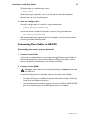
Connecting Data Cables to the AR450S
Connecting the router to your network:
1. Connect to the LAN.
If you have not already done so, use straight-through Ethernet patch cables to
connect the device(s) on your private network (LAN) to the router’s switch
port(s). By default, all switch ports are members of VLAN1.
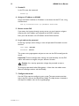
2. Connect to the DMZ port.
If you have a public server to connect, use an Ethernet patch cable to connect it
to the AR450S router’s Ethernet DMZ (ETH1) port. Separating public servers
from your LAN allows the firewall to provide greater protection for your LAN.
If you have multiple public servers, you can connect them to a hub or Layer 2
switch and connect that device to the router’s DMZ port.
3. Connect to the WAN.
Caution If you intend to use a firewall, configure it before you activate
the WAN link.
Once initial configuration is complete, connect the router to the WAN. Use an
Ethernet patch cable to connect the router’s Ethernet WAN (ETH0) port to the
Ethernet port of a WAN device (such as a modem).

14 AR400 Series Router
613-000313 Rev C
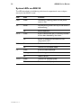
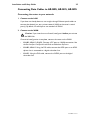
System LEDs on the AR450S
The LEDs described in the following table show the operational status and port
activity for AR450S routers.
LED State Function
Power Green The router is receiving power and the power switch is
ON.
System Red or
Amber
Lit briefly during router start up, or the router is
malfunctioning.
Flashing The fan has failed.
Off Normal operation.
Full Dup Green The port is operating at full-duplex.
Off The port is operating at half-duplex.
Link/ACT Green A link has been established.
Flashing Data is being transmitted.
Off No link is present.
100M Green The port is operating at 100Mbps.
Off The port is operating at 10Mbps.

Installation and Safety Guide 15
613-000313 Rev C
AR415S Router
This section describes how to install the AR415S router.
■ “Installing the AR415S” below
■ “Configuring the AR415S” on page 18
■ “Connecting Data Cables to AR415S” on page 23
■ “System LEDs on AR415S” on page 24
For corresponding information about installing an AR450S, see “AR450S Routers”
on page 7.
For corresponding information about installing an AR440S, AR441S or AR442S, see
“AR440S, AR441S, AR442S Routers” on page 25.
Installing the AR415S
Selecting a Site
You can install the router:
■ on a level surface such as a desktop or bench
■ in a standard 19-inch rack, using the rack-mount kit supplied with the router
When you install the router, choose a site that:
■ allows adequate airflow around the router and its vents
■ is free of dust and moisture
■ will maintain an ambient temperature in the range 0 ºC to 40 ºC
(32 ºF to 104 ºF)
■ will maintain a humidity in the range 5% to 80% non-condensing
■ has a reliable and earthed (grounded) power supply, preferably dedicated and
filtered
■ does not expose cabling to sources of electrical noise such as radio transmitters,
broadband amplifiers, power lines, electric motors, and fluorescent fixtures
■ allows easy access to the router’s power and cable connections
Before Installing the Router
■ Read the safety information “Safety” on page 41.
■ Unpack the router. Verify the package contents. If any items are damaged or
missing, contact your sales representative.

16 AR400 Series Router
613-000313 Rev C
Installing an Optional PIC
If you purchased an optional PIC, install it now by following the Port Interface Card
Quick Install Guide. The PIC Quick Install Guide can be found with the PIC, on the
Documentation and Tools CD-ROM, or can be downloaded from
www.alliedtelesis.com/support/software/ .
Installing the Router in a Rack
1. Gather additional items. You will need:
• the rack-mount kit (in your router package, or ordered from your authorised
Allied Telesis distributor or reseller)
• a Phillips #1 screwdriver
• screws and cage nuts to attach the brackets to your rack
2. Check the rack.
Ensure that the rack is safely secured and that it will not tip over. Devices in a
rack should be installed starting at the bottom, with the heavier devices near the
bottom of the rack.
Ensure the rack has sufficient space for the router and its associated cables. The
router is 1U high.
3. Unscrew the feet from the router.
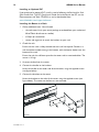
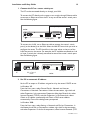
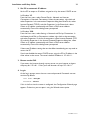
4. Connect the handles to the brackets.
Screw the handles to the wider side of each bracket, using the supplied screws
(see figure below).
5. Connect the brackets to the router.
Screw the brackets to the sides of the router, using the supplied screws (see
figure below). The router can be front or rear mounted.
Rmount

Installation and Safety Guide 17
613-000313 Rev C
6. Mount the router in the rack.
Use appropriate rack mounting screws (not supplied).
Applying Power to the Router
1. Check the supply voltage and the router’s rated voltage.
AR400 Series routers are fitted with a universal mains power supply that will
function over the range 100 VAC to 240 VAC and 50 Hz to 60 Hz.
For continued protection against the risk of fire and shock hazard, replace fuses
only with the same type and rating.
Warning The specific power supply requirements for a particular model are
clearly displayed on the rear or underside of the router. If the supply is outside
the accepted range for the router, the router may not operate or damage to
the router may result.
2. Fit the power cord retaining clip to the AC power inlet on the router’s rear panel.
3. Connect the provided power cord to the AC power inlet and clip it in place.
Switch the router’s power switch to the ON position. The Power LED lights
continuously and the System LED lights briefly. The Port LEDs also light briefly.
The router is supplied with an approved power cord that incorporates a
moulded plug. It must only be used with the power cord supplied.
If the LEDs fail to light, the most likely cause is that the router is not receiving
power. Check that:
■ the power supply outlet’s switch (if any), and the router’s power switch, are in
the ON position
■ the power cable is securely plugged in
■ the power supply is operational

18 AR400 Series Router
613-000313 Rev C
Configuring the AR415S
By default, the DHCP server on the router is enabled, and all the switch ports
belong to the default VLAN (vlan1), which has an IP address of 192.168.1.1 (“Default
Configuration on AR415S, AR440S, AR441S, AR442S” on page 37).
We recommend starting to configure the router using the graphical user interface
(GUI), with its easy wizards. If necessary, you can then use the Command line
interface (CLI) to complete your configuration.
■ “Using the GUI to configure the AR415S” below
■ “Using the CLI to configure the AR415S” on page 21
Using the GUI to configure the AR415S
This section describes how to access the GUI via a switch port in the default VLAN
(vlan1) on the AR415S router, when the PC and the router are in the same subnet,
in order to configure the router.
Caution Only one DHCP server should usually be enabled on a network. If
you have an existing DHCP server, we recommend disabling either it or the
router’s DHCP server. To disable the router’s DHCP server, use the command
line to enter the command:
disable dhcp
If another device on your network already uses the router’s default IP address,
do not connect the router to the network until you have changed the IP
address of the router’s default VLAN (vlan1). Using the command line, enter
the command:
set ip interface=vlan1 ip=ipaddress mask=mask
See the Internet Protocol (IP) chapter in the Software Reference.
The GUI requires a PC running a web browser. Supported browsers are Internet
Explorer 5.0 or later and Netscape 6.2.2 or later, with JavaScript enabled. If you are
using a toolbar or plug-in on your browser to block pop-ups, disable it while using
the GUI. The GUI displays detailed configuration options and information in pop-up
windows.

Installation and Safety Guide 19
613-000313 Rev C
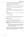
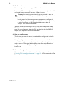
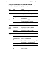
1. Connect the PC to a router switch port.
The PC can be connected directly, or through your LAN.
To connect the PC directly to the router, use a straight-through Ethernet cable
to connect an Ethernet card on the PC to any one of the router’s switch ports.
See the following figure.
To connect via a LAN, use an Ethernet cable to connect the router’s switch
port(s) to the device(s) on the LAN. Select the LAN PC from which you wish to
configure the router. The PC should be in the same subnet as the part of the
LAN that contains the router. For example, the PC could be connected to a hub
or Layer 2 switch that is directly connected to one of the router’s switch ports.
See the following figure.
2. Set PC to automatic IP address.
Set the PC to accept an IP address assigned to it by the router’s DHCP server.
In Windows XP:
From the Start menu, select Control Panel > Network and Internet
Connections > Network Connections. Select the connection, right-click and
select Properties. In the connection Properties dialog box General tab, select
Internet Protocol (TCP/IP), and click Properties. In the General tab, select
Obtain an IP address automatically and Obtain a DNS server address
automatically. Close all the dialog boxes you opened.
In Windows 2000:
From the Start menu, select Settings > Network and Dial-up Connections. In
the Network and Dial-up Connections window, right click on the connection
and select Properties. In the list of components, select Internet Protocol (TCP/
PC
router
switch ports
straight-through cable
POWER
ETH0
ASYN0
SWITCH PORTS
PIC BAY
31
42
POWER
100-240 VAC
50/60 Hz
2.1 A
ON
OFF
PC
router
switch ports
hub or layer 2
switch
3421
10BASE-T/100BASE-TX SWITCH PORTS
POWER
ON
OFF
POWER
ETH0
ASYN0
SWITCH PORTS
PIC BAY
31
42
POWER
100-240 VAC
50/60 Hz
2.1 A
ON
OFF

20 AR400 Series Router
613-000313 Rev C
IP), and click Properties. In the Internet Protocol Properties dialog box, select
Obtain an IP address automatically and Obtain a DNS server address
automatically. Close all the dialog boxes you opened.
If these new IP address settings do not take effect immediately, you may need to
restart the PC.
If you have disabled the router’s DHCP server, assign the PC an IP address in the
same subnet as the router. The router’s default IP address is 192.168.1.1.
3. Browse to the GUI.
If you access the Internet through a proxy server, set your browser to bypass
the proxy for 192.168.1.1. Point your web browser to http://192.168.1.1.
4. Log in.
At the log in prompt, enter the user name and password. Passwords are case
sensitive. By default:
User Name: manager
Password: friend
If this is the first time the router is configured, the Configuration Wizards page
appears. Otherwise, you can open it using the Wizards menu option.
5. Configure the router.
You can configure the router using the GUI wizards or menu.
Important To ensure configuration settings are saved correctly, use the GUI
menus and buttons to navigate, not your browser’s buttons.
Caution As a security precaution, change the password as soon as
possible. Remember the new password, as there is no way to retrieve it if
it is lost.
Use the wizard and other configuration menu options to configure the
router. To change the ‘manager’ password, follow the basic setup wizard,
or select Management > Users from the sidebar menu. Select the
‘manager’ user name and click Modify.
To access context-sensitive help in the GUI, click on the Help button [Help].
The Help button is located at the top of the sidebar menu or on any popup
page. For more information about the GUI, see the Using the Graphical User
Interface (GUI) chapter in the Software Reference.
La pagina si sta caricando...
La pagina si sta caricando...
La pagina si sta caricando...
La pagina si sta caricando...
La pagina si sta caricando...
La pagina si sta caricando...
La pagina si sta caricando...
La pagina si sta caricando...
La pagina si sta caricando...
La pagina si sta caricando...
La pagina si sta caricando...
La pagina si sta caricando...
La pagina si sta caricando...
La pagina si sta caricando...
La pagina si sta caricando...
La pagina si sta caricando...
La pagina si sta caricando...
La pagina si sta caricando...
La pagina si sta caricando...
La pagina si sta caricando...
La pagina si sta caricando...
La pagina si sta caricando...
La pagina si sta caricando...
La pagina si sta caricando...
La pagina si sta caricando...
La pagina si sta caricando...
La pagina si sta caricando...
La pagina si sta caricando...
La pagina si sta caricando...
La pagina si sta caricando...
La pagina si sta caricando...
La pagina si sta caricando...
La pagina si sta caricando...
La pagina si sta caricando...
La pagina si sta caricando...
La pagina si sta caricando...
-
 1
1
-
 2
2
-
 3
3
-
 4
4
-
 5
5
-
 6
6
-
 7
7
-
 8
8
-
 9
9
-
 10
10
-
 11
11
-
 12
12
-
 13
13
-
 14
14
-
 15
15
-
 16
16
-
 17
17
-
 18
18
-
 19
19
-
 20
20
-
 21
21
-
 22
22
-
 23
23
-
 24
24
-
 25
25
-
 26
26
-
 27
27
-
 28
28
-
 29
29
-
 30
30
-
 31
31
-
 32
32
-
 33
33
-
 34
34
-
 35
35
-
 36
36
-
 37
37
-
 38
38
-
 39
39
-
 40
40
-
 41
41
-
 42
42
-
 43
43
-
 44
44
-
 45
45
-
 46
46
-
 47
47
-
 48
48
-
 49
49
-
 50
50
-
 51
51
-
 52
52
-
 53
53
-
 54
54
-
 55
55
-
 56
56


Allied Telesis AR400 series Installation And Safety Manual
- Categoria
- Switch di rete
- Tipo
- Installation And Safety Manual
in altre lingue
- English: Allied Telesis AR400 series
Documenti correlati
Altri documenti
-
Digicom Michelangelo SHDSL Manuale utente
-
Juniper J6350 Getting Started Manual
-
-
LG PCS200R Manuale utente
-
-
Juniper MX204 Manuale utente
-
Juniper PTX1000 Manuale utente
-
AirLive WT-2000ARM Manuale utente
-
Edimax BR-6228NS V2 Manuale utente
-
SMC Networks EZ-Stream SMC2304WBR-AG Manuale utente