
ISTRUZIONI D’USO E DI INSTALLAZIONE
INSTALLATION AND USER’S MANUAL
INSTRUCTIONS D’UTILISATION ET D’INSTALLATION
GEBRAUCHS-UND MONTAGEANLEITUNG
INSTRUCCIONES DE USO Y DE INSTALACION
INSTRUÇÕES DE USO E DE INSTALAÇÃO
D811035 ver. 05 15-01-07
LUX
I
GB
F
D
E
AUTOMAZIONI A PISTONE PER CANCELLI A BATTENTE
PISTON AUTOMATIONS FOR SWING GATES
AUTOMATIONS A PISTON POUR PORTAILS BATTANTS
HYDRAULISCHER DREHTORANTRIEB
AUTOMATIZACIONES A PISTON PARA PORTONES CON BATIENTE
AUTOMATIZAÇÕES A PISTÃO PARA PORTÕES COM BATENTE
P
8
027908 1 1 1 7 4 6
www.BFTGateOpeners.com | (800) 878-7829

LUX Ver. 05 - 3
D811035_05
MANUALE D’USO
ITALIANO
Nel ringraziarVi per la preferenza accordata a questo prodotto, la ditta è
certa che da esso otterrete le prestazioni necessarie al Vostro uso. Leg-
gete attentamente l’opuscolo “Avvertenze” ed il “Libretto istruzioni” che
accompagnano questo prodotto in quanto forniscono importanti indicazioni
riguardanti la sicurezza, l’installazione, l’uso e la manutenzione. Questo
prodotto risponde alle norme riconosciute della tecnica e della disposizioni
relative alla sicurezza. Confermiamo che è conforme alle seguenti direttive
europee: 89/336/CEE, 73/23/CEE (e loro modifiche successive).
2) GENERALITA’
Pistone oleodinamico compatto e robusto, disponibile in svariate versioni a
seconda delle esigenze e del campo di utilizzo. Ci sono modelli con blocchi
idraulici e modelli senza blocchi (reversibili) che, per mantenere il blocco,
necessitano di elettroserratura. Lo sblocco di emergenza si attiva utilizzando
l’apposita chiave.
La forza di spinta si regola con estrema precisione mediante due valvole
by-pass che costituiscono la sicurezza antischiacciamento. Il funzionamento
a fine corsa è regolato elettronicamente nel quadro di comando mediante
temporizzatore.
Sono disponibili versioni speciali con rallentamento in fase di chiusura (mod.
“R”) e mod. “FC” ideali per zone innevate o quando manca la battuta d’arresto
centrale delle ante del cancello (Vedere specifico manuale istruzioni).
3) SICUREZZA
L’automazione, se installata ed utilizzata correttamente, soddisfa il grado di
sicurezza richiesto.
Tuttavia è opportuno osservare alcune regole di comportamento per evitare
inconvenienti accidentali.
• Prima di usare l’automazione, leggere attentamente le istruzioni d’uso e
conservarle per consultazioni future.
• Tenere bambini, persone e cose fuori dal raggio d’azione dell’automa-
zione,in particolare durante il funzionamento.
• Non lasciare radiocomandi o altri dispositivi di comando alla portata dei
bambini onde evitare azionamenti involontari dell’automazione.
• Non contrastare volontariamente il movimento dell’anta.
• Non tentare di aprire manualmente il cancello se:
Nel modello LUX-LUXL-LUXG-LUXGV non è stata sbloccata l’elettro-
serratura con l’apposita chiave.
Nel modello LUXB-LUX2B non è stato azionato lo sblocco con l’apposita
chiave (Fig.1).
• Non modificare i componenti dell’automazione.
• In caso di malfunzionamento, togliere l’alimentazione, attivare lo sblocco
di emergenza per consentire l’accesso e richiedere l’intervento di un
tecnico qualificato (installatore).
• Per ogni operazione di pulizia esterna, togliere l’alimentazione di rete.
• Tenere pulite le ottiche delle fotocellule ed i dispositivi di segnalazione
luminosa. Controllare che rami ed arbusti non disturbino i dispositivi di
sicurezza (fotocellule).
• Per qualsiasi intervento diretto all’automazione, avvalersi di personale
qualificato (installatore).
• Annualmente far controllare l’automazione da personale qualificato.
4) APERTURA MANUALE
Versioni con blocco idraulico (LUXB-LUX2B)
Nei casi di emergenza, per esempio in mancanza di energia elettrica, per
sbloccare il cancello, infilare la stessa chiave “C” usata per la regolazione
delle valvole by-pass nel perno “P” triangolare situato sotto l’attuatore (fig.
1) e ruotarla in senso antiorario. Il cancello è così apribile manualmente
imprimendo una velocità di spinta uguale a quella di apertura automatica.
Per ripristinare il funzionamento elettrico dell’attuatore, girare la chiave in
senso orario fino al completo bloccaggio del perno “P”.
Versione senza blocco idraulico (LUX-LUXL-LUXG-LUXGV)
É sufficiente aprire l’elettroserratura con la relativa chiave e spingere ma-
nualmente l’anta.
5) MANUTENZIONE E DEMOLIZIONE
La manutenzione dell’impianto va fatta eseguire regolarmente da parte
di personale qualificato. I materiali costituenti l’apparecchiatura e il suo
imballo vanno smaltiti secondo le norme vigenti.
AVVERTENZE
Il buon funzionamento dell’operatore è garantito solo se vengono
rispettate i dati riportati in questo manuale. La ditta non risponde dei
danni causati dall’inosservanza delle norme di installazione e delle
indicazioni riportate in questo manuale.
Le descrizioni e le illustrazioni del presente manuale non sono impe-
gnative. Lasciando inalterate le caratteristiche essenziali del prodotto,
la Ditta si riserva di apportare in qualunque momento le modifiche che
essa ritiene convenienti per migliorare tecnicamente, costruttivamente
e commercialmente il prodotto, senza impegnarsi ad aggiornare la
presente pubblicazione.
Thank you for buying this product, our company is sure that you will be more
than satisfied with the product’s performance. The product is supplied with
a “Warnings” leaflet and an “Instruction booklet”. These should both be
read carefully as they provide important information about safety, installa-
tion, operation and maintenance. This product complies with the recognised
technical standards and safety regulations. We declare that this product is in
conformity with the following European Directives: 89/336/EEC/73/23/EEC
(and subsequent amendments).
USER’S MANUAL
ENGLISH
2) GENERAL OUTLINE
A compact, sturdy oleodynamic piston, available in a wide range of models
to fit any need and field of operation. It is available in versions both with or
without (reversible) hydraulic lock, that need to be equipped with an electric
lock to hold the gate both closed and open.
The emergency release is obtained with the special key provided.
The adjustment of the pushing force is extremely precise and is performed
by means of two by-pass valves that act as an antisquash safety. The ope-
ration at the end of the stroke is controlled electronically by a timer in the
control panel.
The LUX series includes special versions with slowdown in the closing phase
(mod. “R”) while the mod. “FC” series is especially suited to areas prone to
heavy snowfalls or where the central gate stop cannot be provided (see
specific instruction manual).
3) SAFETY
If correctly installed and used, this automation device satisfies the required
safety level standards.
However, it is advisable to observe some practical rules in order to avoid
accidental problems.
• Before using the automation device, carefully read the operation instruc-
tions and keep them for future reference.
• Keep children, people and things outside the automation working area,
particularly during its operation.
• Keep radio control or other control devices out of children’s reach, in order
to avoid any unintentional automation activation.
• Do not intentionally oppose the leaf movement.
• Do not attempt to open the gate manually if:
- In mod. LUX-LUXL-LUXG-LUXGV the electric lock has not been released
by means of the appropriate key.
- In mod. LUXB-LUX2B the release has not been activated by means of
the appropriate key (fig.1).
• Do not modify the automation components.
• In case of malfunction, disconnect the power supply, activate the emergency
release to have access to the automation and request the assistance of
a qualified technician (installer).
• Before proceeding to any outside cleaning operation, disconnect the
power supply.
• Keep the photocell optical components and light signal devices clean.
• Check that the safety devices (photocells) are not obscured by branches
or shrubs.
• For any direct assistance to the automation system, request the help of
a qualified technician (installer).
• Have qualified personnel check the automation system once a year.
4) MANUAL OPENING
Versions with hydraulic lock (LUXB-LUX2B)
In case of emergency, for example during a power cut, the gate can be released
by inserting the same key “C” used to adjust the bypass valve into the triangular
pivot “P” found under the actuator (fig. 1) and turning it anti-clockwise. The gate can
then be opened manually following the same speed as an automatic opening.
To restore the actuator to electrical operation, turn the key clockwise until
pivot “P” is locked.
Versions without hydraulic lock (LUX-LUXL-LUXG-LUXGV)
It is sufficient to open the electric lock with its key and move the
leaf manually.
5) MAINTENANCE AND DEMOLITION
The maintenance of the system should only be carried out by qualified
personnel regularly. The materials making up the set and its packing must
be disposed of according to the regulations in force.
WARNINGS
Correct controller operation is only ensured when the data contained in the
present manual are observed. The company is not to be held responsi-
ble for any damage resulting from failure to observe the installation
standards and the instructions contained in the present manual.
The descriptions and illustrations contained in the present manual are
not binding. The Company reserves the right to make any alterations
deemed appropriate for the technical, manufacturing and commercial
improvement of the product, while leaving the essential product fea-
tures unchanged, at any time and without undertaking to update the
present publication.
Fig. 1
www.BFTGateOpeners.com | (800) 878-7829

LUX Ver. 05 - 9
D811035_05
INSTALLATION MANUAL
ENGLISH
Thank you for buying this product, our company is sure that you will be more
than satisfied with the product’s performance. The product is supplied with
a “Warnings” leaflet and an “Instruction booklet”. These should both be
read carefully as they provide important information about safety, installa-
tion, operation and maintenance. This product complies with the recognised
technical standards and safety regulations. We declare that this product
is in conformity with the following European Directives: 89/336 EEC and
73/23/EEC (and subsequent amendments).
1) GENERAL SAFETY
WARNING! An incorrect installation or improper use of the product can
cause damage to persons, animals or things.
• The “Warnings” leaflet and “Instruction booklet” supplied with this
product should be read carefully as they provide important information
about safety, installation, use and maintenance.
• Scrap packing materials (plastic, cardboard, polystyrene etc) according
to the provisions set out by current standards. Keep nylon or polystyrene
bags out of children’s reach.
• Keep the instructions together with the technical brochure for future reference.
• This product was exclusively designed and manufactured for the use
specified in the present documentation. Any other use not specified in
this documentation could damage the product and be dangerous.
• The Company declines all responsibility for any consequences result-
ing from improper use of the product, or use which is different from that
expected and specified in the present documentation.
• Do not install the product in explosive atmosphere.
• The construction components of this product must comply with the following
European Directives: 89/336/EEC, 73/23/EEC and subsequent amend-
ments. As for all non-EEC countries, the above-mentioned standards as
well as the current national standards should be respected in order to
achieve a good safety level.
• The Company declines all responsibility for any consequences resulting
from failure to observe Good Technical Practice when constructing clos-
ing structures (door, gates etc.), as well as from any deformation which
might occur during use.
• The installation must comply with the provisions set out by the fol-
lowing European Directives: 89/336/EEC, 73/23/EEC and subsequent
amendments.
• Disconnect the electrical power supply before carrying out any work on
the installation. Also disconnect any buffer batteries, if fitted.
• Fit an omnipolar or magnetothermal switch on the mains power supply,
having a contact opening distance equal to or greater than 3,5 mm.
• Check that a differential switch with a 0.03A threshold is fitted just before
the power supply mains.
• Check that earthing is carried out correctly: connect all metal parts for
closure (doors, gates etc.) and all system components provided with an
earth terminal.
• Fit all the safety devices (photocells, electric edges etc.) which are needed
to protect the area from any danger caused by squashing, conveying and
shearing.
• Position at least one luminous signal indication device (blinker) where it
can be easily seen, and fix a Warning sign to the structure.
• The Company declines all responsibility with respect to the automation
safety and correct operation when other manufacturers’ components
are used.
• Only use original parts for any maintenance or repair operation.
• Do not modify the automation components, unless explicitly authorised
by the company.
• Instruct the product user about the control systems provided and the
manual opening operation in case of emergency.
• Do not allow persons or children to remain in the automation operation area.
• Keep radio control or other control devices out of children’s reach, in order
to avoid unintentional automation activation.
• The user must avoid any attempt to carry out work or repair on the automa-
tion system, and always request the assistance of qualified personnel.
• Anything which is not expressly provided for in the present instructions,
is not allowed.
• Installation must be carried out using the safety devices and controls
prescribed by the EN 12978 Standard.
• Warning: during the first manoeuvring cycles, some oil may leak out
after being deposited in the breather channel during transport.
• Warning: an excessively fast manual manoeuvre can cause oil to leak
out.
2) GENERAL OUTLINE
A compact, sturdy oleodynamic piston, available in a wide range of models
to fit any need and field of operation. It is available in versions both with or
without (reversible) hydraulic lock, that need to be equipped with an electric
lock to hold the gate both closed and open.
The emergency release is obtained with the special key provided.
The adjustment of the pushing force is extremely precise and is performed by
means of two by-pass valves that act as an antisquash safety. The operation at
the end of the stroke is controlled electronically by a timer in the control panel.
The LUX series includes special versions with slowdown in the closing phase
(Mod. “R”) while the LUX FC series is especially suited to areas prone to
heavy snowfalls or where the central gate stop cannot be provided (see
specific instruction manual).
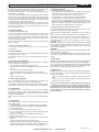
3) THE MAIN PARTS IN THE AUTOMATION (fig. 1)
M)
Single phase 2 pole motor protected by thermal circuit breaker
P) Hydraulic lobe pump
D) Fluid distributor with adjustment valves
C) Cylinder with piston
Standard components:
• gate post and gate brackets - release key and bypass adjustment
• drive capacitor - instruction booklet.
4) TECHNICAL SPECIFICATIONS
Power supply: ......................................................... 230V~±10% - 50 Hz (*)
Motor: ..........................................................................................2800 min
-1
Power absorption: ............................................................................... 250W
Capacitor: .......................................................................................... 6.3 µF
Current absorption: ...............................................................................1.4A
Max. pressure: ................................................................................... 30 bar
Pump delivery: ...........................................................................See Table 1
Pushing force: ....................................................................................3000N
Pulling force: .....................................................................................2600 N
Working stroke: ..........................................................................See Table 1
Impact reaction: ...................................................................hydraulic clutch
Manual manoeuvres: ............................................................ by release key
Max. no. manoeuvres in 24: ....................................................... See table 1
Thermal protection: ........................................................................... 160° C
Ambient temperature: .......................................................... -10° C ÷ 60° C
Protection:............................................................................................IP 57
TABLE 1
MOD
TYPE OF LOCK
PUMP
l/min
WORKING TIME
(s)
MAX.WING
LENGHT/WEIGHT
STROKE
WORKING/TOT
MANOEUVRES
(m) (Kg) (mm) (mm) 24h
LUX
electric lock
1.2 17 2 300 270 290 500
LUX B
hydraulic closing
1.2 17 2 300 270 290 500
LUX 2B
hydraulic clos./open
1.2 17 2 300 270 290 500
LUX L
electric lock
0.6 33 2-4 300/500 270 290 350
LUX G
electric lock
0.6 48 5-2 300/800 390 410 250
LUX GV
electric lock
1.2 28 3,5 300 390 410 500
LUX MB
hydraulic closing
0.9 23 2 300 270 290 500
www.BFTGateOpeners.com | (800) 878-7829

10 - LUX Ver. 05
D811035_05
Controller weight: ................................................................................8.7 kg
Dimensions ...................................................................................:see fig. 2
Circuit oiI ...........................................................................................:idrolux
(*) Special voltages on request
5) INSTALLATION OF THE ACTUATOR
5.1) Preliminary checks
Check:
• that the structure of the gate is rigid and strong enough. In any case, the
actuator must push against a reinforced point in the leaf
• that the leaves move manually without excessive effort for the whole of
their stroke
• that the door stops are mounted on the leaves
• If the gate being installed is not new, check whether its components
are worn.
Repair or replace any worn or damaged parts.
Automation reliability and safety are directly influenced by the condition of
the gate’s structure.
5.2) Installation values
The values to be known for installation can be found in the table related to the
model being installed (fig. 3-4), with reference also to the diagram in fig. 5.
The diagram in fig. 5 uses the following legend:
P
Gate-post fastening rear bracket
F Leaf fastening front fork
a-b “P” bracket installation values
C Distance between fixing points (see fig. 2)
D Gate length
X Distance from gate axis to the edge of the post
Z always over 45 mm (b - X)
kg max. weight of leaf (Table 1)
α° leaf opening in degrees
5.3) How to read the installation dimensions (fig- 3-4)
From the tables (fig. 3-4), select “a” and “b” according to the angle in degrees
α° that the gate has to open. Each table shows the ideal value for “a” and
“b” for an opening of α° = 90° at constant speed.
In this condition, the sum of “a” plus “b” gives the value of the working stroke
“Cu” (fig. 2).
If there is too large a difference between “a” and “b”, the leaf will not travel
smoothly and the pushing or pulling force will fluctuate during its stroke.
When “a” and “b” are at their maximum, the piston develops the maximum
force. This condition is particularly useful for heavy gates or gates with very
long leaves.
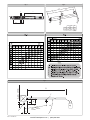
WARNING! The LUX models having a rod with adjustment ball joint enable
the rod to be lengthened or shortened by about 6 mm., but only if it is set
in the position shown in fig. 9 before being installed. When installed, this
adjustment will allow for correcting the stroke of the rod. Fig. 10 shows the
oscillation to which the LUX models with front and rear joint are subject with
respect to the horizontal axis.
5.4) Off-standard installations
Fig. 6 - need for a recess to house the controller when the leaf is completely
opened;Fig. 6 gives the size of the recess for the different LUX models.
Fig. 7 - if the “b” value is higher than the values listed in the installation
tables, the leaf’s hinge pivot should be shifted, or a recess be made in the
gate-post (fig. 8).
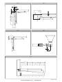
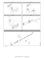
5.5) Mounting the brackets to the gate-post and to the gate-leaf.
Fix the bracket “P” (fig. 11) to the gate-post with a good welding.
The fork “F” should be welded in the same way to the gate leaf along the
distance “C” as shown in fig. 5, taking care that the operator is installed within
the limits shown in Fig. 10.
5.5) Mounting the brackets to the gate-post and to the gate-leaf.
• If the gate-post is in brick, the plate “PF” must be welded to a metal base
(mod. PLE) and set soundly into the post using adequately sized cramps
“Z” welded to the back of the plate (fig. 12).
• If the gate-post is in stone, the plate “PF” welded to a metal base (mod.
PLE) can be fixed with four metal expansion plugs “T” (fig. 13). If a larger
gate is being installed it would be better to weld the plate “PF” to an
angular base (fig. 14).
WARNING: Avoid installing the operator too close to the ground,
so as to prevent rain or snow from being sucked in by the ope-
rator breather.
6) GROUND GATE STOPS
For the controller to operate correctly the gate stops “F” must be used both
in opening and closing, as shown in fig. 15.
The gate stops should prevent the rod of the actuator from reaching its end
of stroke . Fig. 16 gives the values which ensure a perfect installation when
the actuator is performing the pushing or pulling function. They must be
placed so that about a 5-10 mm margin of travel is maintained in the rod.
This margin prevents any malfunctions.
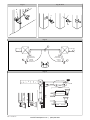
7) FITTING THE ELECTRIC LOCK
This is only necessary on models without a hydraulic lock at closing
end of stroke.
The electric lock mod. EBP (fig. 17) consists of a continuous electromagnet
with ground catch. As long as the gearmotor is operating, this device fea-
tures a non-stop excitation and maintains the bolt “D” lifted until it reaches
the closing end of stroke without creating any friction. This characteristic
enables the pushing force to be reduced in closing which will improve the
antisquash safety level.
8) MOUNTING THE CABLE-CLAMP (fig. 18)
WARNING! Fix the board “B” to the base “F” with the screws “V” provided.
Place the rubber “G” in its seat in the board “B”. Slide the nut “D” onto the
power cable and pass the cable over board “B” as shown in the picture
Tighten nut “D” until the power cable is clamped.
N.B. The board “B” can be fitted onto both the right and left of the base “F”,
as required (see picture).
The bottom of board “B” has a spiralled recess to eventually receive a spiralled
sheath “GS” in PVC (Ø=12 - PG9).
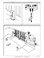
9) THE ELECTRICAL PLANT SET-UP
Set the electrical plant (fig. 19) according to the current standards for electri-
cal plants. Keep the power supply connections definitely separated from the
auxiliary connections (photocells, rubber skirts, control devices, etc.).
WARNING! For connection to the mains, use a multipolar cable with a
minimum of 3x1.5mm
2
cross section and complying with the previou-
sly mentioned regulations. For example, if the cable is out side (in the
open), it has to be at least equal to H07RN-F, but if it is on the inside
(or outside but placed in a plastic cable cannel) it has to be or at least
egual to H05VV-F with section 3x1.5mm
2
.
Perform the connections of the control and safety devices in compliance with
the above mentioned standards.
Fig. 19 indicates the number of connections and the sections for 100 m.
long power supply cables. For distances of over 100 m., calculate the cable
section depending on the automation actual load. If the length of the auxiliary
connections exceeds 50 metres or if they pass through critical areas subject
to disturbances, we advise to disconnect the control and safety devices with
suitable relays.
The connector blocks for the power supply must be placed at a height
greater than that of the actuators so as to avoid oil leakages (Fig. 19).
9.1) Automation main components (fig. 19)
I) Type approved omnipolar switch with 3,5 mm min. contact opening.
provided with overload and short-circuit protection, used to break the
automation connection from the mains. If not present, provide the auto-
mation with a type approved differential switch with adequate capacity
and a 0.03 A threshold.
Qr)
Control unit with built-in receiver
SPL)
Pre-heating board for operation at temperatures below 5° C (optional)
S)
Key selector
AL) Blinker tuned in with antenna and RG58 cable
M) Actuator
Fte) Pair of outside photocells (transmitters)
Fre) Pair of outside photocells (receivers)
Fti) Pair of inside photocells with CF column (transmitters)
Fri) Pair of inside photocells with CF column (receivers)
T) 1-2-4 channel transmitter
IMPORTANT: Before operating the actuator electrically, unscrew the
bleeder screw “S” (fig. 20)found under the joint block and keep it for
future uses. Remove the bleeder screw “S” only after having installed
the actuator.
10) ADJUSTING THE PUSHING FORCE
WARNING: Check that the impact force value measured at the
points established by the EN 12445 standard is lower than that
specified in the EN 12453 standard.
INSTALLATION MANUAL
ENGLISH
www.BFTGateOpeners.com | (800) 878-7829

LUX Ver. 05 - 11
D811035_05
INSTALLATION MANUAL
The adjustment is made by two valves marked “close” and “open” which
control the pushing force during closing and opening respectively.
By turning the valves towards “+”, the force is increased, while by turning
them towards “-” it is reduced.
To ensure an adequate antisquash safety, the pushing force must be adjusted
to just over the push needed to move the leaf, both in closing and opening.
In any event, the pushing force at the end of the leaf, must not exceed the
limits prescribed by the regulations indicated above. For no reason should
the adjustment valves (bypass) be fully closed.
The actuator does not have electric limit switches. Therefore the motors
stop when the working time set in the control unit has expired. The time set
must be increased by 2-5 sec.’s with respect to the time in which the leaves
reach the ground gate stops.
11) MANUAL OPENING
11.1) Versions with hydraulic lock
In case of emergency, for example during a power cut, the gate can be
released by inserting the same key “C” used to adjust the bypass valve
into the triangular pivot “P” found under the actuator (fig. 21) and turning it
anti-clockwise. The gate can then be opened manually following the same
speed as an automatic opening.
To restore the actuator to electrical operation, turn the key clockwise until
pivot “P” is locked.
11.2) Versions without hydraulic lock
It is sufficient to open the electric lock with its key and move the
leaf manually.
12) COVER POSITIONS
The “C” cover of all LUX models can be changed from right to left by inverting
the position of the cap “T” (fig. 23).
To fit the bypass guard (fig. 24), place it in position and insert it under the
rod cover “C”.
13) CHECKING THE AUTOMATION
Before considering the automation completely operational, the following
checks must be made with great care:
• Check that all the components are firmly anchored.
• Control that all the safety means work properly (i.e. photocells, pneumatic
skirt, etc.).
• Check the emergency manoeuvre control.
• Check the opening and closing manoeuvres using the controls.
• Check the control unit’s electronic logic in normal (or customised) ope-
ration.
• Remove the bleeder screw.
14) USE OF THE AUTOMATION
Since the automation may be remote controlled either by radio or a Start
button, it is essential that all safeties are checked frequently.
Any malfunction should be corrected immediately by a qualified specialist.
Keep children at a safe distance from the field of action of the automation.
15) THE CONTROLS
The controls can come in various forms (i.e. manual, remote controlled,
limited access by magnetic badge, etc.) depending on needs and installation
characteristics. For details on the various command systems, consult the
specific instruction booklets.
Anyone using the automation must be instructed in its operation and con-
trols.
16) MAINTENANCE
All maintenance on the controller must be performed with the system’s
power supply shut off.
• Check periodically for oil leaks. To top-up the oil proceed as follows:
a) Screw in the bleeder screw (fig. 20) and remove the controller from the gate.
b) Push the rod right back.
c) Set the controller upright and unscrew the cap O (fig. 18).
d) Use the same type of oil to top up the level until the motor bearing under
the cap “O” is covered.
e) Close the cap “O” and mount the controller back onto the gate.
f) Remove the bleeder screw.
g) Run through 2 complete manoeuvres collecting the excess oil from the
bleeder.
• Check the safety elements on the gate and drive unit.
• For any malfunction that remains unsolved, shut off the power to the system
and call a qualified specialist (the installer). During a breakdown, use the
manual release to allow the gate to be opened and closed by hand.
17) TROUBLE SHOOTING
17.1) Faulty operation of the gearmotor
• Use a suitable instrument to check if there is a voltage across the gear-
motor terminals when an open or close command has been given
• If the motor vibrates but does not turn, this may be due to:
• the common wire C is wrongly connected (it is always light blue)
• the drive capacitor is not connected to the two drive terminals
• if the leaf moves in the wrong direction, invert the drive connections of the
motor in the control unit LEAF STOP: when the operating time set in the
control unit is too short, the leaves may not have time to complete their
stroke. Slightly raise the operating time in the control unit.
17.2) Faulty operation of the electrical accessories
If any of the control and safety components are faulty, this can cause mal-
functions or a breakdown of the whole automation.
If the control unit is equipped with a self-diagnostics system, identify the
fault.
In case of a fault, it is wise to disconnect each of the components in the
automation one at a time, until the one that is causing the fault is found.
After having repaired or replaced it, restore all the components that
were disconnected. For details on each component, refer to its specific
instruction manual.
WARNING:
Any malfunction should be corrected immediately by a qualified
specialist. When carrying out maintenance operations, the area around the
gate should be well marked and barred in order to prevent accidents to
people, animals and objects.
WARNINGS:
Trouble-free operation of the controller can only be guaranteed if the data
given in this manual is respected.
The manufacturer is not liable for damages caused by the failure to respect
safety rules, installation recommendations and instructions given in this
manual.
18) SCRAPPING
Warning: This operation should only be carried out by qualified personnel.
Materials must be disposed of in conformity with the current regulations.
In case of scrapping, the automation devices do not entail any particular
risks or danger. In case of recovered materials, these should be sorted out
by type (electrical components, copper, aluminium, plastic etc.).
19) DISMANTLING
Warning: This operation should only be carried out by qualified personnel.
When the automation system is disassembled to be reassembled on another
site, proceed as follows:
• Disconnect the power supply and the entire external electrical instal
lation.
• In the case where some of the components cannot be removed or are
damaged, they must be replaced.
The descriptions and illustrations contained in the present manual are
not binding. The Company reserves the right to make any alterations
deemed appropriate for the technical, manufacturing and commercial
improvement of the product, while leaving the essential product fea-
tures unchanged, at any time and without undertaking to update the
present publication.
ENGLISH
www.BFTGateOpeners.com | (800) 878-7829

24 - LUX Ver. 05
D811035_05
Fig. 1
Fig. 5
Fig. 2
L2
1025
1300
Cu
270
390
LUX
LUXG 850
715
L1
69x69
83x83
Cu
L1
L2
a
LUX G=1240 mm
LUX= 985 mm
c
X
D
P
F
Kg
b
Z=b-X > 45mm
α°
(mm)
M
P C
D
www.BFTGateOpeners.com | (800) 878-7829

LUX Ver. 05 - 25
D811035_05
Fig. 6
Fig. 10
Fig. 7
Fig. 8 Fig. 9
b
50
a
LUX G 1350 mm
LUX 1100 mm
b
b
b
29
- 6
+ 6
www.BFTGateOpeners.com | (800) 878-7829

26 - LUX Ver. 05
D811035_05
Fig. 11
Fig. 16
Fig. 15
Fig. 12-13-14
SX
DX
F
F
F
OPEN
CLOSE
LUX G 400 mm
LUX 276 mm
LUX 312 mm
LUX 42 mm
LUX G 10 mm
LUX 6 mm
P
Z
PF
T
PF
Sinistra/Left
Gauche/Links
Izquierda
Esquerda
Destra/Right
Droite/Rechts
Derecha
Direita
www.BFTGateOpeners.com | (800) 878-7829

LUX Ver. 05 - 27
D811035_05
Fig. 17 Fig. 18
Fig. 19
O
B
G
D
F
GS
V
2x1.5mm
E
2
I
2
3x1.5mm
S
R
Q
M
M
AL
2
2x1mm
2
Fti
Fri
4x1mm
2
2
2
4x1mm
2
4x1.5mm
3X1mm
2x1mm
Fte
2X1.5mm
RG58
2
2
Fre
CF
CF
4x1.5mm
EBP
T
www.BFTGateOpeners.com | (800) 878-7829

Fig. 20
Fig. 22
Fig. 21
Fig. 23
Fig. 24
P
C
C
T
DX
SX
+
+
-
-
C
www.BFTGateOpeners.com | (800) 878-7829
-
 1
1
-
 2
2
-
 3
3
-
 4
4
-
 5
5
-
 6
6
-
 7
7
-
 8
8
-
 9
9
-
 10
10


BFT LUX L Installation and User Manual
- Categoria
- Gate Opener
- Tipo
- Installation and User Manual
in altre lingue
- English: BFT LUX L
