Carel EVDM011S5 Manuale utente
- Categoria
- Misurazione, test
- Tipo
- Manuale utente

NO POWER
& SIGNAL
CABLES
TOGETHER
READ CAREFULLY IN THE TEXT!
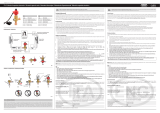
Ratiometric pressure transducer
Evaporator
Solenoid
valve
Liquid
indicator
Filter
Liquid
separator
M
Condenser
EVD ice
E2V/ E3V Unipolar
expansion valve
Evaporator unit
NTC temp. probe
Compressor
P T
WALL
GAS Type
Mode
Super Heat
GAS Type
Mode
Super Heat
GAS Type
Mode
Super Heat
GAS Type
Mode
Super Heat
GAS Type
Mode
Super Heat
GAS Type
Mode
Super Heat
GAS Type
Mode
Super Heat
GAS Type
Mode
Super Heat
Procedura:
Procedure:
Premere DOWN per passare al param.
successivo: Modo di funzionamento
(Mode), indicato dalla barra mediana
Press DOWN to move to the next
parameter: Mode, indicated by the bar in
the middle
Ripetere i passi 2,3,4,5 per modicare i
valori dei param.: Modo di funzionamento
(Mode), Setpoint surriscaldam. (Super Heat)
Repeat steps 2, 3, 4, 5 to set the values
of the other parameters: Mode, Superheat
set point
Premere PRG/Set per 2 s per uscire
dalla procedura di prima messa in servizio
e attivare la regolazione. Il display torna alla
visualizzazione standard (misura di surriscald.).
Press PRG/Set for 2 seconds to exit
commissioning procedure and activate the
regulation. The display returns to standard
visualization (superheat measure).
PARAMETRI DI PRIMA
CONFIGURAZIONE
PARAMETERS FIRST
CONFIGURATION
Gas Type Refriger. (default = 3).
Attenzione: SOLO DURANTE LA PRIMA
MESSA IN SERVIZIO il cambio di
refrigerante comporta il cambio del
valore del parametro sonda raziometrica;
se non specificato in tabella la sonda
raziometrica è di tipo (-1...9.3 barg).
Gas Type Refrigerant (default = 3).
Important: ONLY DURING THE FIRST
COMMISSIONING PROCEDURE the gas
change involves the change of the value
of ratiometric probe parameter; if not
specified in the table the ratiometric
probe is (-1...9.3 barg) type.
Ref. Description Ref. Description Ref. Description
0 Custom (Vedere man. d’uso/ See user man.)
1 R22 15 R422D 29 R455A (-1...12.8 barg)
2 R134a 16 R413A 30 R170 (0...17.3 barg)
3 R404A 17 R422A 31 R442A (-1...12.8 barg)
4 R407C 18 R423A 32 R447A (-1...12.8 barg)
5 R410A 19 R407A 33 R448A
6 R507A 20 R427A 34 R449A
7 R290 21 R245FA 35 R450A (-1...4.2 barg)
8 R600(-1...4.2 barg) 22 R407F 36 R452A (-1...12.8 barg)
9 R600a (-1...4.2 barg) 23 R32 (0...17.3 barg) 37 R508B (-1...4.2 barg)
10 R717 24 HTR01 38 R452B
11 R744 (0...45 barg) 25 HTR02 39 R513A (-1...4.2 barg)
12 R728 26 R23 40 R454B
13 R1270 27 R1234yf 41 R458A
14 R417A 28 R1234ze (-1...4.2 barg)
Modo di regolazione (default = 1)
0: Regolazione customIl modo di
regolazione è impostato a 0 quando
viene modificato uno tra i parametri
seguenti: guadagno proporzionale PID,
Tempo integrale PID, tempo integrale
basso surriscaldamento, tempo integrale
LOP, tempo integrale MOP
1: Banco frigo/cella canalizzati
2: Condizionatore/chiller con
scambiatore a piastre
3: Condizionatore/chiller con
scambiatore a fascio tubiero
4: Condizionatore/chiller con
scambiatore a batteria alettata
5/6: Riservato
7: banco frigo /cella CO2 (R744) sub-critica
8/9: Riservato
10: Condizionatore/chiller con
compressore Digital Scroll
Mode (default = 1)
0: The regulation mode is set to 0
when one of the following parameters
is changed: PID proportional gain, PID
integral time, low superheat integral
time, LOP integral time, MOP integral
time.
1: Centralized cabinet-cold room
2: AC or chiller with plate evaporator
3: AC or chiller with shell tube
evaporator
4: AC or chiller with battery coil
evaporator
5/6: Reserved
7: Centralized cabinet- cold room CO2
(R744) sub-critic
8/9: Reserved
10: Conditioner/chiller with Digital Scroll
compressor
SuperHeat: Set point surriscaldamento
Default = 11 K (20 °F); Min = LowSH
Soglia LowSH; Max = 55 K (99 °F)
SuperHeat: Superheat set point
Default = 11 K (20 °F); Min = LowSH
Threshold LowSH; Max = 55 K (99 °F)
COPIA PARAMETRI CON PC E
SOFTWARE VPM
COPYING THE PARAMETERS
USING A PC & VPM SOFTWARE
Vedere il manuale cod.+0300039IT
See user manual cod.
+0300039EN
EVDM*, EVD ice (230V) - Driver per valvola di espansione elettronica unipolare /
Driver for unipolar electronic expansion valve
+050004265 - rel. 1.1 - 20.10.2020
EVD ice EVD ice
Cod. Descrizione
Description
EVDM011S5* 115/230 V, cablaggio corto
115/230 V, short wiring
EVDM011S6* 115/230 V, cablaggio lungo
115/230 V, long wiring
EVDM011SD* 115/230 V, cablaggio corto,
connettori alimentazione e seriale
115/230 V, short wiring, power
supply and serial network connectors
EVDM011SE* 115/230 V, cablaggio lungo,
connettori alimentazione e seriale
115/230 V, long wiring, power
supply and serial network connectors
(*): 0/1 = imballo singolo/ multiplo (10 pezzi) - single /multiple package (10 pieces)
EVD ice EVD ice
Cod. Descrizione
Description
E2VSTA0330* Statore per E2V (L=300mm, IP67)
Stator for E2V (L=300mm, IP67)
E3VSTA0330* Statore per E3V (L=300mm, IP67)
Stator for E3V (L=300mm, IP67)
SPKT0013P0 Sonda di pressione raziometrica
(-1...9,3 barg)
Ratiometric pressure probe
(-1...9,3 barg)
EVDCAB151K Kit cavi seriale e alimentazione
(L=15 m)
Cable kit for serial network and
power supply (L=15 m)
CVSTDUMOR0 Convertitore USB/RS485
USB/RS485 converter
NOTA: per i codici dei corpi valvola e degli
altri sensori di pressione raziometrici,
vedere il catalogo prodotti CAREL.
NOTE: for valve body and other ratiom.
pressure probes part numbers, see the
CAREL product catalogue.
DESCRIZIONE DESCRIPTION
Il driver EVD ice per valvola di espansione
elettronica CAREL unipolare è un
controllore PID per la regolazione del
surriscaldamento del refrigerante in
un circuito frigorifero. La resinatura
con materiale plastico permette di
raggiungere il grado di protezione IP67e
di proteggere il controllo dall’ambiente
freddo/umido presente all’interno di
una cella frigorifera. Tramite il display è
possibile eseguire la messa in servizio
del driver. La congurazione del driver
può essere eettuata anche tramite
computer, utilizzando il software CAREL
VPM (Visual Parameter Manager),
disponibile sul sito http://ksa.carel.com.
Il driver può essere collegato ad un
controllore CAREL della serie pCO via
seriale, ad un supervisore CAREL o al
controllo per celle frigorifere Ultracella.
The EVD ice driver for electronic
expansion valves with unipolar stepper
motor is a PID controller that manages
the superheat of the refrigerant. The resin
nish with plastic ensures IP67 protection,
as well as protecting the controller against
the cold/humid environment inside the
cold room. The display can be used for
simply conguring and commissioning
the driver. The driver can also be
congured from a computer, using the
CAREL VPM software (Visual Parameter
Manager), available at http://ksa.carel.
com. The driver can be connected to a
CAREL pCO series controller via serial link,
to a CAREL supervisor or to the cold room
control Ultracella.
DIMENSIONI - mm(in) DIMENSIONS - mm(in)
79.4 (3.1)
92.4 (3.6)
∅4.5 (0.2) 170 (6.7)
45.5 (1.8)
61.3 (2.4)
40.7(1.6)
19.6 (0.8)
~230 (9.1)
Nota: Cablaggio corto (S) - lungo (L)/
Note:
Short (S) - long (L) wiring
Cavo /
Cable
(*) Lungh. /
Leng.
(±5%)
Alimentaz. /
Supply
500 (19.7)
RS485 500 (19.7)
Sonda pressione /
Pressure probe
S: 800 (31.5)
L: 2000 (78.7)
Sonda NTC /
NTC probe
S: 800 (31.5)
L: 2000 (78.7)
Cavo statore valvola /
Valve stator cable
300 (11.8)
Ultracap 100 (3.9)
(*) per codici standard CAREL
(*) for standard CAREL codes.
MONTAGGIO MOUNTING
Attenzione:
• INSTALLARE IL CONTROLLO NELL’
EVAPORATORE LONTANO DAI PUNTI
DI FORMAZIONE DI GHIACCIO
• eettuare i collegamenti del cavo
di alimentazione e della seriale in
cassetta di derivazione IP65
• per il montaggio della valvola E2V/
E3V riferirsi alla guida “ExV sistema”
cod.+030220810
Important:
• INSTALL THE CONTROLLER IN THE
EVAPORATOR UNIT, AWAY FROM
POINTS WHERE FROST FORMS
• make the power cable and serial cable
connections in the IP65 junction box
• to install the E2V/E3V valve, see the
“ExV sistema” guide, +030220811
NOTA: EVD ice è fornito senza sonda di
pressione raziometrica e statore valvola,
disponibili come accessori /
NOTE: EVD
ice is supplied without pressure probe and
valve stator, available as accessories.
Segnare sulla parete interna dell’unità
evaporatore le posizioni dei fori ed
eseguirli (Ø<4.5 mm). Avvitare quindi le
viti di ssaggio.
Mark the position of the holes on the wall
inside the evaporator unit, as shown in
the gure, and drill the holes (Ø<4.5 mm).
Then tighten the fastening screws.
TASTIERA KEYPAD
/
UP/DOWN
• Incrementa/ diminuisce il
valore del set point o di ogni
altro parametro selezionato
•
Increases/decreases the
value of the set point or
other selected parameter
PRG/Set
• Al termine della procedura
di prima messa in servizio,
premuto per 2 s, permette
di uscire e di attivare la
regolazione;
• Ingresso/ uscita modo
programmazione, con
salvataggio parametri;
• Reset allarme E8
•
At the end of rst
commissioning procedure, if
pressed for 2 seconds, exits
menu and regulation starts;
• Enter/ exit programming
mode, with parameters
saving;
• Reset E8 alarm
DISPLAY DISPLAY
Il display durante il funzionamento
visualizza il surriscaldamento o eventuali
allarmi (vedere Tabella allarmi).
During operation, the display shows the
superheat value or any alarms (see Alarm
table).
Il punto decimale nel digit a destra
indica lo stato dell’ingresso start/stop
regolazione. Con ingresso chiuso il punto
è acceso lampeggiante.
The decimal point in digit on the right,
displays the start/stop regulation status.
When the inpunt is closed, point is ON
blinking.
PRIMA MESSA IN SERVIZIO FIRST COMMISSIONING
Attenzione:
1. nchè la procedura di prima messa in
servizio non è completata, la regolazione
non è attiva;
2. il cambio di refrigerante comporta il
cambio del tipo di sonda di pressione
raziometrica.
Alimentare il driver: il display si illumina
e il driver si porta in attesa dei parametri
di prima messa in servizio, indicati dalla
barra del display:
Important:
1. as long as the rst commissioning
procedure is not completed, the
regulation is not active;
2. the change of refrigerant involves the
change of type of pressure ratiometric
probe.
Power ON the driver: the display will
be light and driver is waiting the rst
commissioning parameters, showed by
the display bar:
Refrigerante (default=3: R404A)
Tipo di regolazione (default=1:
banco frigo/cella canalizzati)
Setpoint di surriscaldamento
(defaut: 11 K)
Refrigerant (default=3: R404A)
Type of control (default = 1:
multiplexed showcase/cold room
Superheat set point (default: 11 K)
Procedura:
Procedure:
Il display visualizza la barra in alto:
refrigerante (GAS Type):
The display shows the top bar:
refrigerant (GAS Type):
Premere PRG/Set: appare il valore
del refrigerante
Press PRG/Set: the refrigerant
setting is shown
Premere UP/Down per modificare
il valore
Press UP/Down to change the value
Premere PRG/Set per salvare e tornare
al codice (barra in alto) del parametro
refrigerante.
Press PRG/Set to save and return to
the refrigerant parameter code (bar at top).

CAREL INDUSTRIES HQs
Via dell’Industria, 11 - 35020 Brugine - Padova (Italy)
Tel. (+39) 0499716611 – Fax (+39) 0499716600 e-mail: carel@carel.com – www.carel.com
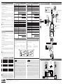
RS485
Modbus®
CVSTDUM0R0
pCO shield shield
PC
VPM
digital input to start
the regulation
230 Vac
ratiometric
pressure
transducer
NTC
bianco/ white - Tx/Rx+
nero/ black - Tx/Rx-
marrone/ brown - L
blu/ blue - N
nero/ black - DI
S2
ULTRACAP
Module
S1
Non rimuovere
il cappuccio
di protezione A!
Do not remove
the protection cap A!
verde/ green - GND
GAS Type
Mode
Super Heat
fascia elastica/ elastic band
fascetta di ssaggio/ fastening band
pasta conduttiva/ conductive cream
A
2
3
4
56
12 3 4 5 6
Valve stator
0,3 Nm
CAREL E V/ EV
unipolar valve
123
123
1 2 3
giallo/ yellow
bianco/ white
verde/ green
rosso/ red
viola/ purple
blu/ blue
1
COLD ROOM
IN
COLD ROOM
OUT
COLD ROOM
OUT
Evaporator
L
N
ON / OFF
EVD ICE
driver
230 V
230 V input
Regulator
P T
EEV
M
Condenser
Electrical panel
Compressor
Condenser
unit
Evaporator
unit
Solenoid
valve
IP65
LN
GAS Type
Mode
Super Heat
GAS Type
Mode
Super Heat
+050004265 - rel. 1.1 - 20.10.2020
Avvertenze per l’installazione:
1. eettuare tutte le operazioni di installazione e manutenzione con
driver non alimentato;
2. evitare cortocircuiti tra i pin L, N.
• EVD ice è un controllo da incorporare nell’apparecchiatura nale,
non usare per montaggio a muro.
• DIN VDE 0100: deve essere garantita la separazione protettiva tra i
circuiti SELV e gli altri circuiti.
Ingressi e uscite
Si raccomanda di tenere separati i cavi degli ingressi/uscite dal cavo di
alimentazione della valvola. Tutti gli ingressi analogici e le seriali (non
optoisolate) sono riferiti alla massa GND, quindi l’applicazione, anche
temporanea, di tensioni superiori a ±5 V a questi collegamenti può
causare un danno irreversibile al driver.
Prima messa in servizio
Alimentare il driver, il display si illuminerà e in caso di prima messa
in servizio, con il display è possibile immettere i 3 parametri
necessari all’avvio: tipo refrigerante, tipo di regolazione, setpoint di
surriscaldamento.
Attenzione: la maggior parte dei refrigeranti prevede la sonda di
pressione raziometrica cod.
SPKT0013P0
(-1...9,3 barg). Per l’installazione
con altre sonde raziometriche di pressione, vedere il manuale EVD ice,
cod. +0300038IT scaricabile, anche anteriormente all’acquisto, dal sito
www.carel.com.
Alimentazione 115...230V ac (+10/-15%) 50/60 Hz.
Assorbimento max 15 W
Alimentazione di
emergenza
13 Vdc +/-10%. (Se installato il modulo
opzionale Ultracap per EVD ice)
Driver Valvola unipolare
Collegamento statore
valvola
Cavo a 6 poli tipo AWG 18/22 con connettore
“superseal” IP67
Collegamento ingressi
digitali
Ingresso digitale 230 Vac optoisolato.
Corrente di chiusura: 10 mA.
Lmax=10m per ambiente residenziale/
industriale, 2m per ambiente domestico
S1 Sonda pressione
raziom. (0…5V)
Risoluzione 0,1 % fs
Errore di misura:
2% fs massimo; 1% tipico
S2 Sonda
temperatura NTC:
10 kΩ a 25°C, -50T90°C
Errore di misura:
1°C nel range -50T50°C;
3°C nel range +50T90°C
Collegamento seriale
RS485
Modbus, Lmax=500m, cavo schermato, connes.
a terra da entrambi i lati del cavo schermato
Montaggio con viti
Dimensioni Base x altezza x profondità = 93 x 230 x 41 mm
Condizioni di funzion. -30T40°C; <90% U.R.
Condizioni di immagaz. -35T60°C, <90% U.R. non condensante
Grado di protezione IP65/IP67
Inquin. ambientale 2
Temperatura per prova
lo incandescente
850°C
Immunità contro
le sovratensioni
Categoria II
Classe di isolamento II
Classe e struttura
del software
A
Conformità Sicurezza elettrica EN 60730-1, UL 60730-1,
UL 60730-2-9
Compatibilità
elettromagnetica
EN 61000-6-1, EN 61000-6-2,
EN 61000-6-3, EN 61000-6-4
EN61000-3-2, EN55014-1,
EN61000-3-3
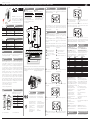
LIMITI MINIMO E MASSIMO DI SURRISCALDAMENTO
Nel caso di allarme sonda guasta, è possibile che la misura del
surriscaldamento fuoriesca dall’intervallo di visualizzazione ammesso
-5...55 K (-9...99°F). Il display visualizza allora il codice dell’allarme sonda
guasta (A1/A2) e:
Caso 1 Caso 2
Se la misura del surriscaldamento
è inferiore a -5 K, il display mostra
i due segmenti inferiori.
Se la misura del surriscaldamento
è superiore a 55 K, il display
mostra i due segmenti superiori.
Power supply 115 to 230V ac (+10/-15%) 50/60 Hz.
Power consumption 15 W
Emergency power
supply
13 Vdc +/-10% (If the optional Ultracap module
for EVD ice is installed)
Driver Unipolar valve
Valve stator connection 6-wire cable type AWG 18/22 with “superseal”
IP67 connector
Digital inputs
connection
Digital input 230 Vac optoisolated.
Closing current: 10 mA.
Lmax=10 m for residential/industrial
environments, 2 m for domestic environments
S1
Ratiometric
pressure probe
(0…5V)
Resolution 0.1 % fs
Measurement error:
2% fs maximum; 1% typical
S2
Temperature
NTC probe:
10 kΩ at 25°C, -50T90°C
Measurement error:
1°C in the range -50T50°C;
3°C in the range +50T90°C
RS485 serial connection Modbus, Lmax=500 m, shielded cable, earth
both ends of the cable shield
Assembly with screws
Dimensions Base x height x depth = 93 x 230 x 41 mm
Operating conditions -30T40°C; <90% RH
Storage conditions -35T60°C, <90% RH non-condensing
Index protection IP65/IP67
Environmental pollution 2
Temperature for glow
wire test
850°C
Overvoltage category Category II
Insulation class II
Class and software
structure
A
Conformity Electrical safety EN 60730-1, UL 60730-1,
UL 60730-2-9
Electromagnetic
compatibility
EN 61000-6-1, EN 61000-6-2,
EN 61000-6-3, EN 61000-6-4
EN61000-3-2, EN55014-1,
EN61000-3-3
MINIMUM AND MAXIMUM SUPERHEAT LIMITS
In case of broken probe alarm, the superheat measure may come out
of the allowed visualization interval -5 to 55 K (-9...99°F). The display
shows the code (A1/A2) and:
Case 1 Case 2
If the superheat measure is
lower than -5 K, the display
shows the two bottom leds.
If the superheat measure is
higher than 55 K, the display
shows the two top leds.
Installation warnings:
1.
all installation and maintenance operations must be performed with
the driver not powered;
2.
avoid short-circuits between pins L, N.
•
The EVD ice controller is integrated into an appliance, do not use for
wall mounting.
•
DIN VDE 0100: protective separation must be guaranteed between
the SELV circuits and the other circuits.
Inputs and outputs
It is recommended to keep the input/output and relay cables separate
from the valve power cable. All the analogue inputs and the serial
ports (not optically isolated) refer to GND, and consequently applying,
even temporarily, voltages greater than ±5 V to these connections may
cause irreversible damage to the driver.
First start-up
Power on the driver, the display will come on and when starting for the
rst time, will guide the installer through the entry of the 3 parameters
required to start operation: refrigerant type, type of control, superheat
set point.
Important: the majority of refrigerants matches with the ratiometric
pressure probe SPKT0013P0 (-1...9.3 barg). For installation with other
ratiometric pressure probes, see the EVD ice manual, cod. +0300038EN,
available for download at www.carel.com, even prior to purchase.
INSTALLAZIONE CARATTERISTICHE TECNICHE TECHNICAL CHARACTERISTICS
INSTALLATION
TABELLA ALLARMI ALARM TABLE
Cod. Allarme Alarm
EE EEprom
EEprom
A1 Sonda S1
Probe S1
A2 Sonda S2
Probe S2
E1 MOP-alta pressione evaporazione
MOP-high evaporation pressure
E2 LOP-bassa pressione
evaporazione
LOP-low evaporation pressure
E3 Basso surriscaldamento
Low Superheat
E4 Bassa temperatura di aspirazione
Low suction temperature
E5
Chiusura di emergenza: LowSH,
LOP, MOP, bassa T/P di aspirazione,
mancanza alimentazione
Emergency closure: LowSH,
LOP, MOP, low suction T/P, no
power supply
E6 Allarme di rete
Net alarm
E7 Basso livello carica Ultracap
Low level Ultracap charge
E8 Chiusura valvola non completata
Valve not completly closed
NO POWER
& SIGNAL
CABLES
TOGETHER
READ CAREFULLY IN THE TEXT!
ATTENZIONE: separare quanto più possibile i cavi delle sonde
e degli ingressi digitali dai cavi dei carichi induttivi e di potenza per evitare
possibili disturbi elettromagnetici. Non inserire mai nelle stesse canaline
(comprese quelle dei quadri elettrici) cavi di potenza e cavi di segnale.
ATTENZIONI IMPORTANTI: Il prodotto CAREL è un prodotto avanzato,
il cui funzionamento è specifi cato nella documentazione tecnica fornita col
prodotto o scaricabile, anche anteriormente all’acquisto, dal sito internet www.
carel.com. Il cliente (costruttore, progettista o installatore dell’equipaggiamento
finale) si assume ogni responsabilità e rischio in relazione alla fase di
configurazione del prodotto per il raggiungimento dei risultati previsti in
relazione all’installazione e/o equipaggiamento finale specifi co. La mancanza
di tale fase di studio, la quale è richiesta/indicata nel manuale d’uso, può
generare malfunzionamenti nei prodotti finali di cui CAREL non potrà essere
ritenuta responsabile. Il cliente finale deve usare il prodotto solo nelle modalità
descritte nella documentazione relativa al prodotto stesso. La responsabilità di
CAREL in relazione al proprio prodotto è regolata dalle condizioni generali di
contratto CAREL presenti nel sito www.carel.com e/o da specifi ci accordi con
i clienti.
NO POWER
& SIGNAL
CABLES
TOGETHER
READ CAREFULLY IN THE TEXT!
WARNING: separate as much as possible the probe and digital
input signal cables from the cables carrying inductive loads and power cables
to avoid possible electromagnetic disturbance. Never run power cables
(including the electrical panel wiring) and signal cables in the same conduits.
IMPORTANT WARNINGS: The CAREL product is a state-of-the-art device,
whose operation is specified in the technical documentation supplied with
the product or can be downloaded, even prior to purchase, from the website
www.carel.com. The customer (manufacturer, developer or installer of the
final equipment) accepts all liability and risk relating to the configuration of
the product in order to reach the expected results in relation to the specific
final installation and/or equipment. The failure to complete such phase, which
is required/indicated in the user manual, may cause the final product to
malfunction; CAREL accepts no liability in such cases. The customer must use
the product only in the manner described in the documentation relating to
the product. The liability of CAREL in relation to its products is specified in the
CAREL general contract conditions, available on the website www.carel.com
and/or by specific agreements with customers.
SMALTIMENTO DEL PRODOTTO:
l’apparecchiatura (o il prodotto) deve
essere oggetto di raccolta separata
in conformità alle vigenti normative
locali in materia di smaltimento
DISPOSAL OF THE PRODUCT:
The appliance (or the product)
must be disposed of separately in
accordance with the local waste
disposal legislation in force.
NOTA: per l’installazione delle
sonde vedere la “Guida al sistema
EEV” (+030220810) /
NOTE: for the probes installation
see the “Guide to EEV System”
(+030220811).
NTC
SCHEMA DI COLLEGAMENTO CONNECTION DIAGRAM
SCHEMA ELETTRICO PER IL CONTROLLO
DEL SURRISCALDAMENTO WIRING DIAGRAM FOR SUPERHEAT CONTROL
-
 1
1
-
 2
2


Carel EVDM011S5 Manuale utente
- Categoria
- Misurazione, test
- Tipo
- Manuale utente
in altre lingue
- English: Carel EVDM011S5 User manual
Documenti correlati
-
Carel E5V Manuale utente
-
Carel UltraCella Assembly And Installation
-
Carel SmartCella 3PH WP00B24A10 Quick Manual
-
Carel AX3000 Istruzioni per l'uso
-
-
-
-
-
Carel PJ easy XL Manuale utente