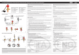
Schema di collegamento al EVD evolution /
EVD evolution connection
diagram
G
G0
VBAT
DI1
GND
DI2
EVD evolution
2 AT
24 Vac
230 Vac
35 VA
TRADRFE240
(dedicato)
G
G0
VBAT
Ultracap Technology
Fig. 1
Nota: il modulo va collegato al EVD evolution come indicato in figura.
Note: the module is connected to the EVD evolution as shown in the figure.
Smaltimento: l’apparecchiatura (o il prodotto) deve essere oggetto di raccolta separata in
conformità alle vigenti normative locali in materia di smaltimento. /
Disposal: the appliance
(or the product) must be disposed of separately in compliance with the local standards in
force on waste disposal.
NO POWER
& SIGNAL
CABLES
TOGETHER
READ CAREFULLY IN THE TEXT!
Attenzione: separare quanto più possibile i cavi delle sonde e degli ingressi digitali dai
cavi dei carichi induttivi e di potenza per evitare possibili disturbi elettromagnetici. Non
inserire mai nelle stesse canaline (comprese quelle dei quadri elettrici) cavi di potenza
e cavi di segnale. /
Warning: separate as much as possible the probe and digital input
signal cables from the cables carrying inductive loads and power cables to avoid
possible electromagnetic disturbance. Never run power cables (including the electrical
panel wiring) and signal cables in the same conduits.
Il modulo Ultracap EVD0000UC0 è un dispositivo opzionale che
permette di completare il prodotto EVDEvo con un modulo di backup
esterno per chiusura valvole in caso di mancanza di alimentazione di rete.
Il modulo garantisce l’alimentazione temporanea al EVDEvo (singolo o
twin) in caso di mancanza di tensione di alimentazione, per il tempo
sufficiente alla chiusura immediata delle valvole elettroniche (una o due)
connesse ad esso. Tramite il suo utilizzo si può evitare quindi l’installazio-
ne nel circuito frigo della valvola solenoide, o del kit batteria tampone.
Il modulo è realizzato tramite condensatori Ultracap tampone
(EDLC=Electric Double Layer Capacitor), la cui ricarica è gestita autono-
mamente dal modulo stesso. Il condensatore Ultracap assicura un’affi-
dabilità in termini di vita componente molto più lunga rispetto ad un
modulo realizzato con batterie al piombo: la vita stimata del modulo
UltraCap è di 10 anni. Inoltre non utilizzando batterie al piombo non
richiede particolari avvertenze in termini di sicurezza e inquinamento.
Nota importante:
Quando avviene la chiusura di emergenza, i condensatori si scaricano
completamente. Quindi la carica assicura una sola chiusura delle valvole.
Al ritorno dell’alimentazione i condensatori iniziano a ricaricarsi, è neces-
sario quindi un tempo in funzione del numero (una o due) e dal tipo di
valvola connessa, prima di poter garantire una nuova chiusura in caso di
black-out. Nel caso di due valvole CAREL, ad esempio, per accumulare
energia sufficiente per poter garantire la chiusura servono 4 minuti di
carica. E’ necessario quindi assicurarsi che nel controllo macchina (pCO,
MPX, o affine) sia impostato un ritardo di accensione compressore dopo
il power-on di almeno 4 minuti. In questo modo è garantito dal controllo
macchina che le valvole rimangono chiuse per tutto il tempo necessario
alla ricarica del modulo Ultracap. Per un sola valvola CAREL, il ritardo di
accensione deve essere di 3 minuti.
Avvertenza: EVD evolution può essere alimentato con tensione
alternata 24 Vac o con tensione continua 24 Vdc. Con alimenta-
zione a tensione continua, in caso di mancanza di alimentazione
EVDEvo non esegue la chiusura di emergenza della valvola, anche
se connesso il modulo batteria EVBAT00400 o il modulo Ultracap
EVD0000UC0.
Range di valvole supportate:
- Standard CAREL: tutte i modelli valvole CAREL;
- Terze parti: Alco, Sporlan, Danfoss (per i modelli fare riferimento al foglio
istr. pCO
5
cod +0500040ML, par. “Driver valvola espansione elettronica”).
Contenitore plastico
• materiale: tecnopolimero;
• autoestinguenza: V2 (secondo UL94);
• prova biglia: 100 °C;
• resistenza alle correnti striscianti: 250 V;
• colore: RAL7035.
The EVD0000UC0 Ultracap module is an optional external backup
device for the EVDEvo used to close the valves in the event of mains
power failures. The module guarantees temporary power to the EVDEvo
(single or twin) in the event of power failures, for enough time to
immediately close the connected electronic valves (one or two). It avoids
the need to install a solenoid valve in the refrigerant circuit or use the
backup battery module. The module is made using Ultracap storage
capacitors (EDLC=Electric Double Layer Capacitor), which are recharged
independently by the module. Ultracap capacitors ensure reliability in
terms of much longer component life than a module made with lead
batteries: the calculated life of the Ultracap module is at least 10 years. In
addition, not using lead batteries also means no special precautions are
required regarding safety and pollution
Important note:
When emergency closing occurs, the capacitors discharge completely.
Consequently the charge can only ensure one valve closing operation.
When power returns the capacitors start recharging, meaning a certain
amount of time is needed, according to the number (one or two) and
type of valve connected, before being able to guarantee another closing
operation in the event of blackout. With two CAREL valves, for example,
a charging time of 4 minutes is needed to store enough energy to close
both valves. As a result, make sure that the control unit (pCO, MPX etc.)
is set with a compressor start delay after power-on of at least 4 minutes.
This guarantees that the valve remains closed for the entire time needed
to recharge the Ultracap module. For just one CAREL valve, the start delay
must be set to 3 minutes.
Warning: EVD evolution can be supplied at 24 Vac or 24 Vdc. With
direct current power supply, in the event of power failures EVDEvo
doesn’t performe emergency closing of the valve, even if the
EVBAT00400 battery module or the EVD0000UC0 Ultracap module
is connected.
Range of valves supported:
- Standard CAREL: all models of CAREL valves;
- Other parts: Alco, Sporlan, Danfoss (for the list of models see the pCO
5
instruction sheet code +0500040ML, par. “Electronic expansion valve driver”).
Plastic case
• material: technopolymer;
• flame retardance: V2 (UL94);
• ball pressure test: 100 °C;
• resistance to creeping current: 250 V;
• colour: RAL7035.
EVD0000UC0: Modulo ultracap per EVD evolution / ultracap Module for EVD Evolution
cod. +0500042IE rel. 1.1 - 08.07.11

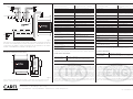
Caratteristiche tecniche Modulo Ultracap:
Alimentazione per carica 24 Vac/ 24 Vdc ± 15% , in parallelo
al driver
Potenza assorbita in ingresso 10 VA (solo in fase di carica)
Tensione di uscita Vbat 18.4 Vdc
Massima corrente di uscita 0,5 A
Tempo di carica della batteria Ultracap 4 minuti per 2 valvole CAREL
5 minuti per 2 valvole terze parti
N.ro di azionamenti chiusura valvole
consecutivi, in funzionamento tampone
1
Condizioni di funzionamento -25T60 °C, < 90% U.R. non condensante
Condizioni di immagazzinamento -40T70 °C, < 90% U.R. non condensante
Grado di protezione del frontale IP20
Protezione contro le scosse elettriche Dispositivo da incorporare in apparec-
chiature di classe I e/o II
Grado di inquinamento ambientale Tipo 2
Tipo azioni 1.L
Immunità contro le sovratensioni Classe II
Limiti di temperatura delle superfici Come condizioni di funzionamento
Montaggio Su guida DIN
Lunghezze cavi alimentazione e di
collegamento
Inferiore a 5 m
PTI dei materiali per isolamento PCB: PTI250
insulation material: PTI 175
Periodo delle sollecitazioni elettriche
delle parti isolanti
lungo
Categoria di resistenza al calore e al
fuoco
Categoria D (UL94 - V2)
Immunità contro le sovratensioni Categoria II
Caratteristiche di invecchiamento (ore
di funzionamento)
80.000
Categoria di immunità al surge
(CEI EN 61000-4-5)
Categoria III
Tab. 1
Il dispositivo non è destinato ad essere tenuto in mano quando alimentato.
Certificazione di Prodotto
Sicurezza elettrica:
EN 60730-1,
UL60950
Compatibilità
elettromagnetica:
EN 61000-6-1, EN 61000-6-2, EN 61000-6-2/EC,
EN 61000-6-2/IS1, EN61000-6-3, EN 61000-6-4
CAREL Industries HQs
Via dell’Industria, 11 - 35020 Brugine - Padova (Italy)
Tel. (+39) 0499716611 – Fax (+39) 0499716600 – www.carel.com – e-mail: [email protected]
cod. +0500042IE rel. 1.1 - 08.07.11
Carel si riserva la possibilità di apportare modifiche o cambiamenti ai propri prodotti senza alcun
preavviso. /
Carel reserves the right to modify the features of its products without prior notice.
AVVERTENZE IMPORTANTI:
Il prodotto CAREL è un prodotto avanzato, il cui funzionamento è specificato nella
documentazione tecnica fornita col prodotto o scaricabile, anche anteriormente all’ac-
quisto, dal sito internet www.carel.com. Il cliente (costruttore, progettista o installatore
dell’equipaggiamento finale) si assume ogni responsabilità e rischio in relazione alla
fase di configurazione del prodotto per il raggiungimento dei risultati previsti in rela-
zione all’installazione e/o equipaggiamento finale specifico.La mancanza di tale fase di
studio, la quale è richiesta/indicata nel manuale d’uso, può generare malfunzionamenti
nei prodotti finali di cui CAREL non potrà essere ritenuta responsabile.Il cliente finale
deve usare il prodotto solo nelle modalità descritte nella documentazione relativa al
prodotto stesso. La responsabilità di CAREL in relazione al proprio prodotto è regolata
dalle condizioni generali di contratto CAREL editate nel sito www.carel.com e/o da
specifici accordi con i clienti.
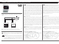
Schema di collegamento al pCO
5
/
pCO
5
connection diagram
80 VA
2.5 AT
C7
NO7
C7
NO8
C8
NC8
NO13
C13
NC13
C9
NO9
NO10
NO11
C9
ID1
ID2
ID3
ID4
ID5
ID6
ID7
ID8
IDC1
B6
B7
B8
GND
ID9
ID10
ID11
ID12
IDC9
ID13H
ID13
IDC13
ID14
ID14H
J7
J8
J29
J14
J28
J17
J18
J15
J6
J30
J27
VBAT
G0
G
GND
VREF
S1
S2
S3
S4
DI1
DI2
G
G0
driver
G
G0
VBAT
Ultracap Technology
CAREL E
X
V
valve A
1 3 2 4
1 3 2 4
CAREL E
X
V
valve B
G
G0
NO12
C12
NC12
J16
Fig. 2
Il modulo può essere collegato anche al pCO
5
come indicato in figura (in alternativa
al modulo “nero” PCOS00UC20) inseribile sulla plastica). /
The module can also be
connected to the pCO5, as shown in the figure (as an alternative to the “black”
module, code PCOS00UC20, installed on the plastic case).
Dimensioni (mm)/Dimensions (mm)
70
60
110
45
49
Ultracap Technology
Fig. 3
MPORTANT WARNINGS:
The CAREL product is a state-of-the-art device, whose operation is specified in the
technical documentation supplied with the product or can be downloaded, even
prior to purchase, from the website www.carel.com. The customer (manufacturer,
developer or installer of the final equipment) accepts all liability and risk relating to the
configuration of the product in order to reach the expected results in relation to the
specific final installation and/or equipment. The failure to complete such phase, which
is required/indicated in the user manual, may cause the final product to malfunction;
CAREL accepts no liability in such cases. The customer must use the product only in the
manner described in the documentation relating to the product. The liability of CAREL
in relation to its products is specified in the CAREL general contract conditions, avai-
lable on the website www.carel.com and/or by specific agreements with customers.
Ultracap module technical specifications:
Charge power supply 24 Vac / 24 Vdc ± 15% , in parallel with
the driver
Power input
10 VA (only during recharging cycle)
Output voltage Vbat 18.4 Vdc
Maximum output current 0.5 A
Ultracap charge time 4 minutes for two-
CAREL valve
5 minutes for 2 third party valves
Number of consecutive valve closing
operations in backup mode
1
Operating conditions:
-25T60 °C, < 90% RH non-condensing
Storage conditions
-40T70 °C, < 90% RH non-condensing
Front panel protection
IP20
Protection against electric shock
Device to be integrated into class I
and/or II equipment
Environmental pollution Type 2
Type of action 1.L
Immunity against voltage surges Class II
Surface temperature limits Same as operating conditions
Assembly On DIN rail
Power and connection cable lengths Less than 5 m
PTI of insulating materials PCB: PTI250
insulation material: PTI 175
Period of stress across the insulating
parts
long
Category of resistance to heat and fire Category D (UL94 - V2)
Overvoltage protection Category II
Ageing characteristics (operating
hours)
80.000
Category of immunity to voltage
surges (IEC EN 61000-4-5)
Category III
Tab. 1
The device is not designed to be hand-held when powered.
Product certification
Electrical safety: EN 60730-1, UL60950
Electromagnetic
compatibility:
EN 61000-6-1, EN 61000-6-2, EN 61000-6-2/EC,
EN 61000-6-2/IS1, EN61000-6-3, EN 61000-6-4
-
 1
1
-
 2
2


in altre lingue
- English: Carel EVD0000UC0 Quick start guide
Documenti correlati
-
Carel E5V Manuale utente
-
Carel UltraCella Assembly And Installation
-
Carel pCO3 series Technical Leaflet
-
-
Carel SmartCella 3PH WP00B24A10 Quick Manual
-
-
-
-
-