Tecnosystemi Built-in tangential air curtain Manuale del proprietario
- Tipo
- Manuale del proprietario

1
MANUALE D’USO / USER MANUAL
Tecnosystemi S.p.A. - Società Benefit
www.tecnosystemi.com
via dell’Industria, 2/4 - Z.I. San Giacomo di Veglia
31029 Vittorio Veneto (Treviso) - Italy
Phone +39 0438.500044 Fax +39 0438.501516
Numero Verde 800 904474 (only for Italy)
email: [email protected]
C.F. - P. IVA - R.I.TV IT02535780247 | Cap. Soc. € 5.000.000,00 i.v.
REV. 08 / 01-08-2022
COD. C60000437
BARRIERE D’ARIA TANGENZIALI AD INCASSO
CON RESISTENZA ELETTRICA
BUILT-IN TANGENTIAL AIR CURTAINS
WITH ELECTRIC RESISTANCE
• cod. 12450014R2 • cod. 12450014R3 • cod. 12450024R2
• cod. 12450024R3 • cod. 12450034R2 • cod. 12450034R3
ELEGANCE TR

2
Le barriere d’aria Tecnosystemi sono state studiate e realizzate per permettere di ottimizzare la resa degli impianti di
climatizzazione dei locali in cui viene installata, compatibilmente con la necessità da parte degli utenti di accedere ed uscire
dai locali spesso in modo continuativo, evitando così di aprire e chiudere continuamente le porte, permettendo un notevole
risparmio economico, e riducendo quasi a zero la dispersione termica. La barriera d’aria, posizionata internamente sopra la
porta d’ingresso, genera un flusso d’aria che spinto velocemente verso il basso, crea una netta separazione tra il volume
d’aria interna e quella esterna, permettendo così di climatizzare correttamente gli ambienti senza alcuna dispersione, sia
nella stagione estiva che in quella invernale.
Altri vantaggi sono determinati dalla notevole riduzione di consumo energetico e dall’impedimento dell’entrata di gas di
scarico, polvere anche a porte aperte all’interno dei locali. La barriera d’aria funziona a tre velocità, con la possibilità di poterla
variare utilizzando il telecomando in dotazione.
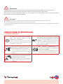
IMPORTANTE!
L’installazione della barriera d’aria deve essere eseguita da personale qualificato e in accordo alla norma CEI 64.8
(collegamento elettrico) .
Le barriere d’aria Tecnosystemi si installano sopra la porta, ad una altezza minima di 1,8 mt dal suolo, posizionandola in
modo che la bocca della barriera sia centrata con l’apertura dell’ingresso. La barriera non dev’essere mai installata all’esterno
della porta o in luogo esposto alle intemperie (pioggia, vento). Assicurarsi che in nessun modo possa venire a contatto con
pioggia, o aspiri acqua perché potrebbero esserci problemi di corto circuiti o scosse. Ogni macchina viene venduta completa
di cavo di alimentazione. Il fissaggio dev’essere eseguito ancorando la barriera d’aria al soffitto ancorando le quattro staffette
mediante l’utilizzo di N°4 barre filettate M8. Rimane responsabilità dell’installatore scegliere il tipo di fissaggio più idoneo per
il tipo di muratura sulla quale verrà applicata la barriera.
IMPORTANT!
The air curtain must be installed by qualified operators and in accordance with standard IEC 64.8 (electrical connection).
Tecnosystemi air curtains are installed above doors, at a height of at least 1.8 metres from the ground, positioning them in such a
way that the air curtain outlet is centred with the opening. The air curtain must never be installed on the outside of the door or in
places that are exposed to adverse weather conditions (rain, wind). Make sure that it cannot come into contact with rain or sucks up
water because this could result in short circuits or electric shocks. Every air curtain is supplied with a power cable. Installation must
be carried out by fixing the air curtain to the ceiling with the four brackets using 4 x M8 threaded rods. It is the installer’s responsibility
to choose the most suitable type of fastening based on the brickwork on which the air barrier is to be installed.
DESCRIZIONE / DESCRIPTION
AVVERTENZE DI SICUREZZA / SAFETY WARNINGS
Tecnosystemi air curtains have been designed and manufactured to optimise the performance of air conditioning and heating
systems in the premises in which they are installed, where users frequently and continuously enter and exit the premises, thus
eliminating the need to continually open and close the doors. The result is a significant economic saving by virtually reducing
any heat loss to zero. The air curtain, positioned inside above the entrance, creates an air flow which, when rapidly pushed
downwards distinctly separates the internal and external volumes of air, allowing climate regulation in rooms without any
losses, both in the summer and winter.
Other benefits are a significant reduction in energy consumption and the prevention of exhaust fumes and dust entering even
when the doors inside the premises are open. The air curtain operates at three speeds which can be varied using the remote
control supplied.

3
INSTALLAZIONE
La barriera d’aria deve essere installata solo in posizione orizzontale.
La barriera d’aria può essere installata sopra l’apertura della porta. Devono essere mantenute le distanze adeguate da
materiali infiammabili per un utilizzo sicuro della barriera d’aria.
La barriera d’aria deve operare in spazi asciutti e coperti con una temperature ambiente tra i 5° C e +40° umidità relativa
fino a 80%. La barriera d’aria non è destinata a muovere aria che contiene combustibile o miscele combustibili, fumi chimici,
polvere grossa, veleno, germi infettivi, ect.
INSTALLATION
The air curtains should only be installed in a horizontal position.
The air curtains can be installed above the door opening. Adequate distances from flammable materials must be maintained for safe
use of the air barrier. The air curtains must operate in dry and covered spaces with an ambient temperature between 5 ° C and + 40°
relative humidity up to 80%. The air curtains is not intended to move air that contains fuel or combustible mixtures, chemical fumes,
coarse dust, poison, infectious germs, ect.
ATTENZIONE! / WARNING!
LE BARRIERE D’ARIA CON RESISTENZA ELETTRICA, NON PERMETTENDO L’USO DEL KIT AVVIO AUTOMATICO
AIR CURTAINS WITH ELECTRIC RESISTANCE, NOT ALLOWING THE USE OF THE AUTOMATIC STARTING KIT
Solo materiali non infiammabili (quelli che non bruciano, che bruciano senza fiamma o si riducono in cenere) o materiali (quelli
che non bruciano, che bruciano prevalentemente senza fiamma ad es. il cartongesso) possono trovarsi entro 100 mm dalla
barriera d’aria). Tuttavia questi materiali non devono bloccare le aperture (feritoie) di entrata e uscita. .
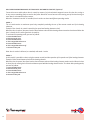
Per le barriere d’aria con resistenza la distanza di sicurezza dalle superfici strutturali dello stabile e da oggetti infiammabili sono
le seguenti:
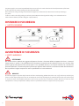
La distanza di sicurezza da materiali infiammabili posizionati in direzione del flusso d’aria principale (ad es. dietro lo scarico) è 500
mm. La distanza di sicurezza da materiali infiammabili posizionati sopra la barriera d’aria è 500 mm, la distanza di sicurezza da
materiali infiammabili posizionati in altre direzioni è 100 mm.
La barriera d’aria è fissata al soffitto da 4 barre filettate (non incluse nella spedizione / fornitura).
In loco è necessario verificare l’alimentazione corretta affinché sia compatibile con l’utilizzo esatto della barriera d’aria basato
sui parametri elettrici della stessa.
E’ necessario tagliare o fare un foro rispettando le dimensioni sotto riportate.
Praticare 4 fori nel soffitto come da schema dimensioni (vedi “dimensioni”) per appendere la barriera d’aria ancorandola in 4 punti.
Fissare la barriera d’aria al soffitto avendo cura di lasciare spazi tra la scocca ed il soffitto o utilizzare 4 barre filettate per
raggiungere la distanza ottimale dal soffitto (vedi “condizioni di sicurezza e funzionalità corretta della barriera d’aria”).
Only non-flammable materials (those which do not burn, which burn without a flame or turn to ash) or materials (those which
do not burn, which mainly burn without a flame, e.g. plasterboard) can be placed within 100 mm of the air curtain. These
materials, however, must not block the inlet and outlet openings (slats).
For air curtains with resistance the safety distance from the surfaces of the building and from flammable objects are as follows:
The safety distance for flammable materials is 500 mm.
The safety distance from flammable materials placed above the air barrier is 500 mm,
The safety distance from flammable materials positioned in other directions is 100 mm.
The air curtain should be fixed to the ceiling with 4 threaded rods (not included in the delivery/supply). You must check on-site that
AVVERTENZE DI INSTALLAZIONE
/ INSTALLATION WARNINGS

4
the power supply is correct and compatible with the exact use of the air curtain based on the electrical parameters of the latter.
A cut or hole must be made according to the sizes indicated below.
Drill 4 holes in the ceiling according to the dimensions diagram (see “dimensions”) to attach the air curtain by anchoring it
in 4 places.
Fix the air curtain to the ceiling, taking care to leave space between the housing and the ceiling, or use 4 threaded rods to
achieve the best distance from the ceiling (see “safety distance”).
DISTANZE DI SICUREZZA
/ SAFETY DISTANCES
AVVERTENZE DI SICUREZZA
/ SAFETY WARNINGS
ATTENZIONE!
Non infilare le dita o qualsiasi altro oggetto nell’apertura di uscita o di entrata dell’aria ad apparecchio fermo, o durante il
funzionamento, in quanto c’è la possibilità di ferirsi. Se durante la normale marcia la barriera si blocca, non cercare di farla
ripartire agendo manualmente sulla ventola perché c’è la possibilità di ferirsi o di scariche elettriche, far controllare da
personale qualificato. E’ vietato manipolare il prodotto per apportare delle modifiche, o verificare anomalie di funzionamento.
Per le riparazioni rivolgersi sempre ad un tecnico specializzato o al centro assistenza.
WARNING!
Do not insert fingers or any other object into the air inlet or outlet opening, whether the device is on or off, as this may result in injury.
If the air curtain stops during normal use, do not attempt to restart it by adjusting the fan manually because this may result in injury
or an electric shock. Call a qualified technician to check it. Do not, under any circumstances, tamper with the air curtain to make
modifications or check for malfunctions. Always contact a specialised technician or support centre for any repairs.

5
IMPORTANTE!
E’ vietato lavare la barriera con getti d’acqua o versandoci sopra prodotti liquidi, potrebbero provocare corto circuiti.
Prima di effettuare qualsiasi operazione sulla barriera staccare la spina dalla presa di alimentazione.
Non utilizzare il prodotto nelle stanze da bagno o in altri ambienti dove ci sia un’ umidità elevata o in presenza di spruzzi
d’acqua.(Grado di protezione della barriera IP 20).
IMPORTANT!
It is forbidden to wash the air curtain with jets of water or by pouring liquids onto it; this may cause short circuits.
Disconnect the plug from the wall outlet before any maintenance operation.
Do not use the product in bathrooms or in any rooms where there is a high level of humidity or water spray. (Degree of protection of
the air curtain IP 20).
La barriera d’aria deve essere scollegata
dalla rete elettrica prima di ogni
installazione o riparazione.
/ The air curtain must be disconnected from
the mains supply before carrying out any
installation or repair work.
La barriera non deve essere utilizzata al di fuori
della gamma di temp.indicata nel manuale
d’uso o in atmosfere aggressive o a rischio di
esplosione. / The air curtain must not be used
outside the temperature range indicated in the
user manual or in aggressive atmospheres or if
there is a risk of explosion.
Non posizionare radiatori o altri
dispositivi in prossimità del cavo di
alimentazione della barriera d’aria.
/ Do not place any radiators or other
devices near the power cord of the air
curtain.
Non utilizzare apparecchiature o
conduttori danneggiati per collegare la
barriera d’aria alla rete.
/ Do not use damaged equipment or wires
to connect the air curtain to the mains.
Nell’installare la barriera d’aria, seguire
le normative di sicurezza specifiche per
le apparecchiature elettriche.
/ When installing the air curtain, follow the
specific safety regulations for electrical
equipment.
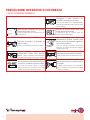
PRECAUZIONI DI MONTAGGIO
/ ASSEMBLY WARNINGS

6
PRECAUZIONI OPERATIVE DI SICUREZZA
/ SAFETY OPERATING WARNINGS
Non bloccare il condotto aria quando
la barriera d’aria è accesa.
/ Do not block the air duct when the air
curtain is on.
Non lavare la barriera d’aria con acqua.
Proteggere le parti elettriche del
ventilatore dall’ingresso di acqua.
/ Do not wash the air curtain with water.
Protect the electrical parts of the fan from
water seepage.
Staccare la barriera d’aria dalla rete
prima della manutenzione.
/ Disconnect the air curtain from the
mains before maintenance.
Impedire ai bambini di utilizzare la
barriera d’aria.
/ Do not let children use the air curtain.
Non danneggiare il cavo di
alimentazione durante l’utilizzo della
barriera d’aria. Non mettere oggetti sul
cavo di alimentazione.
/ Do not damage the power cord when
using the air curtain. Do not place objects
on the power cord.
Tenere prodotti esplosivi ed
infiammabili lontano dalla barriera
d’aria. / Keep explosive and flammable
products away from the heat air curtain.
Non aprire la barriera d’aria in funzione.
/ Do not open the air curtain when it is on.
In caso di rumori insoliti, fumo,
staccare la barriera d’aria dalla presa di
corrente e contattare il servizio clienti.
/ In case of unusual noises or smoke,
disconnect the air curtain from the wall
outlet and contact customer service.
Non lasciare che l’aria in uscita dalla
barriera d’aria punti su fiamme aperte
o candele.
/ Make sure that the air emitted by
the air curtain is not directed at naked
flames or candles.

7
MOD. COD.
PESO
/
WEI-
GHT
[kg]
VEL
ARIA
ALLA
BOCCA
/ AIR
SPEED
AT
OUTLET
[m/s]
PORTA-
TA
ARIA
/ AIR
FLOW
[m3/h]
LIVELLO
SONO-
RO
/ SOUND
LEVEL
dB
(A)
Δ°C
ARIA
CON
RESIS.
/ Δ°C
AIR
WITH
RE-
SIST.
TEN-
SIONE
ALI-
MENT.
/
POWER
SUPPLY
VOLTA-
GE
POTEN-
ZA
ASSOR-
BITA
/ AB-
SORBED
POWER
[W]
POTEN-
ZA
CON
RESIST. ½
CARICO
/ POWER
WITH
RESIST. ½
LOAD
[W]
POTENZA
CON
RESIST.
PIENO
CAR.
/ POWER
WITH
RESIST.
FULL LOAD
[W]
PER POR-
TONI CON
DIM.
/ FOR DO-
ORS WITH
DIMEN-
SIONS
[mm]
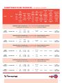
BARRIERE D’ARIA TANGENZIALE CON 2 RESISTENZE A RESISTENZA ELETTRICA
/
TANGENTIAL AIR CURTAINS WITH 2 ELECTRIC HEATING ELEMENTS
1100
BARRIERA
AD INCASSO
12450014R2
23
I: 8
II: 9
III: 10
I: 692
II: 753
III: 948
I: 47
II: 52
III: 54 12 220 Vac
50 Hz 75 W 1900 W 3800 W L = 1000
H MAX 2200
H MIN 1800
BARRIERE D’ARIA TANGENZIALE CON 3 RESISTENZE A RESISTENZA ELETTRICA
/
TANGENTIAL AIR CURTAINS WITH 3 ELECTRIC HEATING ELEMENTS
1100
BARRIERA
AD INCASSO
12450014R3
24
I: 8
II: 9
III: 10
I: 678
II: 738
III: 929
I: 47
II: 52
III: 54 15 400 Vac
50 Hz 75 W 3800 W 5700 W L = 1000
H MAX 2200
H MIN 1800
BARRIERE D’ARIA TANGENZIALE CON 4 RESISTENZE A RESISTENZA ELETTRICA
/
TANGENTIAL AIR CURTAINS WITH 4 ELECTRIC HEATING ELEMENTS
1500
BARRIERA
AD INCASSO
12450024R2
35 I: 8
II: 9
III: 10
I: 1.112
II: 1.213
III: 1.263
I: 51
II: 54
III: 55 19 400 Vac
50 Hz 190 W 3200 W 6400 W L = 1500
H MAX 2200
H MIN 1800
2000
BARRIERA
AD INCASSO
12450034R2
49 I: 8
II: 9
III: 10
I: 1.090
II: 1.189
III: 1.238
I: 49
II: 52
III: 53 19 400V
50 Hz 190 W 3800 W 7600 W L = 2000
H MAX 2200
H MIN 1800
BARRIERE D’ARIA TANGENZIALE CON 6 RESISTENZE A RESISTENZA ELETTRICA
/
TANGENTIAL AIR CURTAINS WITH 6 ELECTRIC HEATING ELEMENTS
1500
BARRIERA AD
INCASSO
12450024R3
36
I: 8
II: 9
III: 10
I: 1.090
II: 1.189
III: 1.238
I: 52
II: 55
III: 56 25 400 Vac
50 Hz 190 W 6400 W 9600 W L = 1500
H MAX 2200
H MIN 1800
2000
BARRIERA AD
INCASSO
12450034R3
50
I: 8
II: 9
III: 10
I: 1.068
II: 1.165
III: 1.213
I: 50
II: 53
III: 54 25 400 Vac
50 Hz 190 W 7600 W 11400 W L = 2000
H MAX 2200
H MIN 1800
CARATTERISTICHE TECNICHE / TECHNICAL FEATURES

8
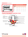
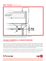
DIMENSIONI / DIMENSIONS [mm]
MODELLO
/ MODEL A B C D E
1100 1086 362 270 396 1120
1500 1440 362 270 396 1472
2000 2040 362 270 396 2072
DIMENSIONI / DIMENSIONS
ON
MODE
OFF
PULSANTE
BARRIERA D’ARIA ON
/ AIR CURTAIN ON BUTTON PULSANTE VELOCITA’ MASSIMA
/ MAXIMUM SPEED BUTTON
PULSANTE VELOCITA’ MEDIA
/ MEDIUM SPEED BUTTON
PULSANTE VELOCITA’ MINIMA
/ MINIMUM SPEED BUTTON
PULSANTE
BARRIERA D’ARIA OFF
/ AIR CURTAIN OFF BUTTON
Simbolo velocita’ ventilazione
selezionata (Led verde)
/ Selected ventilation speed
symbol (Green LED) Pulsante selezione 1/2 carico
resistenza o carico intero
resistenza
/ Selection button 1/2 load
resistance or full load resistance
Simbolo mezzo carico
resistenza (Led giallo)
/ Half load resistance symbol (yellow LED)
Simbolo carico
intero resistenza (Led arancione)
/ Full load resistance symbol (orange LED)
UTILIZZO TELECOMANDO BARRIERA D’ARIA
/ USING THE AIR CURTAIN REMOTE
CD
B
A
E

9
1. ACCENSIONE / 1. TURN ON
- On / accensione dell’apparecchio
- On / turning the appliance on
2. SPEGNIMENTO / 2. TURN OFF
- Off/ spegnimento apparecchio
- Off / turning the appliance off
3. IMPOSTAZIONE DI VELOCITÀ / 3. SPEED SETTING
Velocità minima / Low speed
Velocità media / Medium speed
Velocità massima
/ Maximum speed
4. SIMBOLI DI FUNZIONAMENTO
/ 4. SYMBOLS
MODE - Permette di selezionare le seguenti modalita’ di funzionamento
MODE - It allows you to select the following operating modes.
Indicazione velocita’ ventilazione selezionata (Led verde)
Selected ventilation speed indicator (green LED)
Resistenza 1/2 carico (icona colore giallo)
Le resistenze installate nella barriera d’aria funzionano a mezzo carico
Half load resistance (yellow icon)
The heating elements installed in the air curtain work at half load
Resistenza pieno carico (icona colore arancione
Le resistenze installate nella barriera d’aria funzionano a pieno carico
Full load resistance (orange icon)
The heating elements installed in the air curtain work at full load
ON
OFF
MODE
DESCRIZIONE UTILIZZO TASTI TELECOMANDO
/ DESCRIPTION OF USE OF REMOTE CONTROL BUTTONS
ETICHETTA CRUSCOTTO MONTATA A BORDO MACCHINA / DASHBOARD LABEL INSTALLED ON THE MACHINE
/ Full load (orange LED)
/ Half load (yellow LED)/ IR Receiver
Pieno Carico (Led arancione)
1/2 Carico (Led giallo)
3° velocita’ (Max) 3 LED ACCESI / 3rd speed (Max) 3 LEDs ON
2° velocita’ (Med) 2 LED ACCESI / 2nd speed (Med) 2 LEDs ON
1° velocita’ (Min) 1 LED ACCESO / 1st speed (Min) 1 LED ON
Ricevitore IR
ETICHETTA CRUSCOTTO BARRIERA D’ARIA / DASHBOARD LABEL

10
WARNING! BEFORE PERFORMING MAINTENANCE OPERATIONS, DISCONNECT THE ELECTRICAL POWER SUPPLY
BY TURNING THE MAIN SWITCH “OFF”.
Tecnosystemi air curtains can be installed above the door positioned so that the air curtain vent is lined up with the centre of
the door opening. The air curtain must never be installed on the outside of the door or in places that are exposed to adverse
weather conditions (rain, wind).
Make sure that it cannot come into contact with rain or suck up water because this could result in short circuits.
The air curtain must be secured to the wall using the holes on the back panel. It is the installer’s responsibility to choose the most
suitable type of fastening based on the brickwork on which the air barrier is to be installed.
Always leave a space of at least 15 cm between the upper protection grille and the ceiling, to allow the air curtain to draw in air;
also, do not obstruct it with sheets or panels.
Each machine is sold complete with power plug and remote control.
ATTENZIONE! PRIMA DI ESEGUIRE LE OPERAZIONI DI MANUTENZIONE TOGLIERE L’ALIMENTAZIONE
ELETTRICA POSIZIONANDO L’INTERRUTTORE GENERALE DELL’IMPIANTO SU “SPENTO.
INSTALLAZIONE E MESSA IN OPERA
/ INSTALLATION AND COMMISSIONING
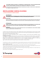
IMPORTANTE!
L’INSTALLAZIONE DELLE BARRIERE DEVE ESSERE ESEGUITA DA PERSONALE QUALIFICATO E IN ACCORDO
ALLA NORMA CEI 64.8. (COLLEGAMENTO ELETTRICO), E SECONDO QUESTO MANUALE.
IMPORTANT!
THE AIR CURTAIN MUST BE INSTALLED BY QUALIFIED PERSONNEL AND IN COMPLIANCE WITH THE ITALIAN ELEC-
TROTECHNICAL COMMITTEE STANDARD IEC 64.8. (ELECTRICAL CONNECTION), AND ACCORDING TO THIS MANUAL.
ATTENZIONE!
PRIMA DI EFFETTUARE LA MESSA IN OPERA DELLA BARRIERA D’ARIA ASSICURARSI CHE LA STESSA NON
SIA COLLEGATA ALLA RETE ELETTRICA, ED INDOSSARE I GUANTI IN GOMMA DI PROTEZIONE.
WARNING!
BEFORE COMMISSIONING THE AIR CURTAIN, MAKE SURE THAT IT IS NOT CONNECTED TO THE ELECTRICAL POWER
SUPPLY AND WEAR PROTECTIVE RUBBER GLOVES.
Le barriere d’aria Tecnosystemi possono essere installate sopra la porta, posizionandola in modo che la bocca della
barriera sia centrata con l’apertura dell’ingresso. La barriera non deve mai essere installata all’esterno della porta o in
luogo esposto alle intemperie (pioggia…vento…).
Assicurarsi che in nessun modo possa venire a contatto con pioggia, o aspiri acqua perché potrebbero esserci
problemi di cortocircuito.
E’ obbligatorio il fissaggio della barriera alla muratura tramite i fori realizzati sulla schiena. Rimane responsabilità
dell’installatore scegliere il tipo di fissaggio più idoneo per il tipo di muratura sulla quale verrà applicata la barriera.
Bisogna che sia sempre lasciato uno spazio di almeno 15 cm. tra la griglia di protezione superiore e il soffitto del
locale, per permettere alla barriera di aspirare aria; e non ostruire con teli o pannelli ad incasso.
Ogni macchina viene venduta completa di spina di alimentazione e di telecomando.

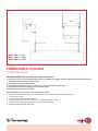
11
446
396
1,8 mt
MOD. 1100 L = 767
MOD. 1500 L = 1140
MOD. 2000 L = 1739
DO NOT INSTALL the air curtain in the following conditions:
1. Make sure that it cannot come into contact with rain or suck up water because this could
cause short circuits.
2. In the presence of flammable vapours.
3. Temperature above +40°C or below -10°C.; relative humidity ≥90%.
4. In the presence of explosive mixtures or in the presence of gas.
5. Relative humidity higher than 90%.
NON INSTALLARE la barriera d’aria nelle seguenti condizioni:
1. Assicurarsi che in nessun modo possa venire a contatto con pioggia, o aspiri acqua perché queste condizioni
potrebbero essere causa di corto circuiti.
2. In presenza di vapori infiammabili.
3. Temperatura superiore a +40°C o inferiore a -10°C.; umidità relativa ≥90%.
4. In presenza di miscele esplosive o in presenza di gas.
5. Umidità relativa superiore al 90%.
CONDIZIONI DI UTILIZZO
/ CONDITIONS OF USE

12
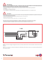
IMPORTANT!
while making the electrical connection, the installer must respect the polarities indicated on the plate located in front
of the power supply terminal board:
- L1-L2-L 3 (connect the line cable: all of the safety protections are inserted in it)
- N (connect the neutral cable)
- Earth (connect the green/yellow cable, which is 1 cm longer than L and N).
IMPORTANTE!
DURANTE IL COLLEGAMENTO ELETTRICO, L’INSTALLATORE DEVE RISPETTARE LE POLARITÀ INDICATE DALLA
TARGHETTA POSTA DAVANTI ALLA MORSETTIERA DI ALIMENTAZIONE:
- L1-L2-L 3 (collegare il conduttore di linea: internamente risultano inserite tutte le protezioni di
sicurezza)
- N (collegare il connettore di neutro)
- Terra (collegare il conduttore giallo verde avente una lunghezza superiore di 1 cm rispetto L e N).
NOTA: è necessario collegare il disgiuntore termico, dei motori elettrici ad un sistema ausiliario di interruzione trifase
esterno.
NOTE: it is necessary to connect the thermal circuit breaker of the electric motors to an external auxiliary hold-off
three-phase system.
INTERRUTTORE DI PROTEZIONE MAGNETO-TERMICA ONNIPOLARE CONFORME A EN 61508:1
/ UNIVERSAL MAGNETO-THERMAL PROTECTION SWITCH IN ACCORDANCE WITH EN 61508: 1
V 400
L1
L1
GN
L2L2
L3
N
L3
N

13
Questo kit venduto separatamente alla barriera d’aria permette di collegare direttamente l’accensione e lo
spegnimento della macchina con l’apertura e la chiusura della porta.
This kit, sold separately from the air curtain, allows you to switch the machine on and off by opening and closing the door.
KIT AVVIO AUTOMATICO PER BARRIERA D’ARIA
/ AUTOMATIC KIT START
IMPOSTAZIONE DELLE MODALITÀ DI FUNZIONAMENTO DELLA BARRIERA D’ARIA CON “KIT AVVIO
AUTOMATICO” (optional)
Collegare il sensore dotato di cavetto alla barriera d’aria mediante jack, fissare il sensore magnetico A alla cassa
della porta o in un punto solido con il telaio del serramento. Fissare il secondo sensore alla parte mobile dell’infisso
lasciando uno spazio massimo tra i due sensori di circa 2 cm.
Con l’installazione del “kit avvio automatico” la barriera ha la possibilità di operare in due differenti modalità di
funzionamento:
MODALITÀ’ 1
La barriera funziona solamente alla massima velocità escludendo totalmente l’utilizzo del telecomando e delle
resistenze elettriche.
Esempio;
Porta chiusa, barriera in stand-by (nessuna velocità e resistenza elettrica attiva).
Apro la porta, la velocità passa al valore massimo e la resistenza elettrica rimane disattiva.
Chiudo la porta, la barriera ritorna in stand-by.
Per attivare questa modalità di funzionamento procedere come segue:
1. Premere il pulsante ON
2. Scollegare il jack
3. Premere il pulsante ON
4. Il led arancione si accenderà
5. Premere il pulsante ON
6. Il led arancione si spegnerà
7. Ricollegare il jack
Nota: la barriera viene consegnata, di serie, con modalità 1 attiva.
MODALITÀ’ 2
In questa modalità è possibile selezionare, tramite il telecomando, sia il funzionamento delle velocità che delle
resistenze elettriche.
Esempio:
Seleziono velocità minima e la resistenza elettrica.
Apro la porta, la velocità passa al valore massimo e la resistenza elettrica rimane attiva.
Chiudo la porta, la barriera ritorna alla velocità minima con resistenza elettrica attiva.
Per attivare questa modalità di funzionamento procedere come segue:
1. Premere il pulsante ON
2. Scollegare il jack
3. Premere il pulsante ON
4. Il led arancione si accenderà
5. Ricollegare il jack

14
AIR CURTAIN OPERATING MODES SETTINGS WITH “AUTOMATIC START KIT” (optional)
Connect the sensor with cable to the air curtain by means of a jack and attach magnetic sensor A to the door casing or
in any case to something firmly secured to the frame. Attach the second sensor to the moving part of the door leaving no
more than 2 cm between the two sensors.
When the “automatic start kit” is installed, the air curtain can have two different operating modes.
MODE 1
The air curtain works at maximum speed only, completely excluding the use of the remote control and of the heating
elements.
Example. Door closed, air curtain in stand-by (no speed and heating element active).
When the door is opened, the speed reaches the maximum value and the heating element remains deactivated. When the
door is closed, the air curtain goes back in stand-by.
To activate this operating mode, proceed as follows:
1. Press the ON button
2. Disconnect the jack
3. Press the ON button
4. The orange LED will turn on
5. Press the ON button
6. The orange LED will turn off
7. Reconnect the jack
Note: the air curtain is delivered, as standard, with mode 1 active.
MODE 2
In this mode it is possible to select, using the remote control, both the operation of the speeds and of the heating elements.
Example. Select the minimum speed and the heating element.
When the door is opened, the speed reaches the maximum value and the heating element remains active. When the door
is closed, the air curtain goes back to the minimum speed with the heating element active. To activate this operating mode,
proceed as follows:
1. Press the ON button
2. Disconnect the jack
3. Press the ON button
4. The orange LED will turn on
5. Reconnect the jack

15
Le barriere d’aria non necessitano di particolare manutenzione. Per la pulizia esterna utilizzare un detergente
neutro con un panno umido per rimuovere la polvere, ed utilizzare un panno asciutto per eliminare i residui.
Effettuare una soffiatura con aria compressa dirigendo il getto verso la ventola e il vano motore per rimuovere la
polvere depositata. Il numero di interventi va effettuato in funzione dell’utilizzo del prodotto, si consiglia comunque
un controllo ogni 2/3 mesi e di effettuare una prova di funzionamento ad ogni inizio di stagione.
DATI TECNICI / TECHNICAL DATA
BARRIERA D’ARIA
/ AIR CURTAIN
Air curtains do not require any special maintenance. For external cleaning, use a neutral detergent with a damp cloth to
remove dust and use a dry cloth to eliminate any residual dust. Blow compressed air by aiming the jet at the fan and motor
compartment to remove any dust deposits. The number of interventions should be based on the use of the air curtain. It is,
however, advisable to carry out a check every 2/3 months and to do a test run at the beginning of each season.
PULIZIA E CONTROLLI E MANUTENZIONE
/ CLEANING AND CHECKS
INSTALLAZIONE DEL SENSORE PER IL KIT AVVIO AUTOMATICO DELLA BARRIERA
INSTALLING THE SENSOR FOR THE AUTOMATIC AIR CURTAIN START KIT

16
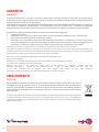
SMALTIMENTO
DISPOSAL
GARANZIA
WARRANTY
Alla fine della sua vita utile il prodotto non deve essere smaltito insieme ai rifiuti urbani. Può essere
consegnato presso gli appositi centri di raccolta differenziata predisposti dalle amministrazioni
comunali, oppure presso i rivenditori che forniscono questo servizio. Per rimarcare l’obbligo di smaltire
separatamente gli elettrodomestici, sul prodotto è riportato il marchio del contenitore di spazzatura
mobile barrato.
At the end of its useful life, the product must not be disposed of with household waste. It can be deposited at
a dedicated recycling centre run by local councils, or at retailers who provide such a service. To highlight the
requirement to dispose of household electrical items separately, there is a crossed-out waste paper basket
symbol on the product.
La garanzia ha durata di 1 (uno) anno a decorrere dalla data di consegna indicata sul d.d.t (bolla). E’ prevista altresì
l’estensione d’ufficio, a titolo gratuito, per il secondo anno (due anni complessivi di garanzia) con decorrenza sempre
dalla data indicata nel d.d.t di consegna (bolla).
L’azienda fornitrice garantisce la qualità dei materiali impiegati e la corretta realizzazione dei componenti. La garanzia
copre difetti di materiale e di fabbricazione e si intende relativa alla fornitura dei pezzi in sostituzione di qualsiasi
componente che presenti difetti, senza che possa venir reclamata alcuna indennità, interesse o richiesta di danni.
La garanzia non copre la sostituzione dei componenti che risultano danneggiati per:
• trasporto non idoneo;
• installazione non conforme a quanto specificato in questo manuale di installazione uso e manutenzione;
• la non osservanza delle specifiche tecniche di prodotto;
• quant’altro non riconducibile a vizi originari del materiale o di produzione a condizione che il reclamo del cliente
sia coperto dalla garanzia e notificato nei termini e modalità richiesta dal fornitore, lo stesso si impegnerà, a sua
discrezione, a sostituire o riparare ciascun prodotto o le parti di questo che presentino vizi o difetti.
The warranty is valid for 2 (two) years from the delivery date indicated on the delivery note / waybill.
The supplier company guarantees the quality of the materials used and the correct construction of the components. The
warranty covers defects in materials and manufacturing defects and refers to the supply of spare parts of any components
featuring defects, without any compensation, interest or claim for damages.
The warranty does not cover the replacement of components damaged due to:
incorrect transportation;
installation not compliant with that specified in this installation, use and maintenance manual;
non-observance of product technical specifications;
Anything else that is not linked to original faults of the material or production provided that the
customer complaint is covered by the guarantee and a claim is made within the time limit and
in the way requested by the supplier, the same supplier will commit, at their own discretion,
to replace or repair any product or part of product showing signs of faults or defects.

NOTE
NOTES
17

·
W
E
A
R
E
A
B
E
N
E
F
I
T
C
O
M
P
A
N
Y
·
W
E
A
R
E
A
B
E
N
E
F
I
T
C
O
M
P
A
N
Y
·
W
E
A
R
E
A
B
E
N
E
F
I
T
C
O
M
P
A
N
Y
Tecnosystemi S.p.A. Società Benefit
www.tecnosystemi.com
via dell’Industria, 2/4 - Z.I. San Giacomo di Veglia
31029 Vittorio Veneto (Treviso) - Italia
Tel +39 0438.500044 - Fax +39 0438.501516
email: [email protected]
C.F. - P. IVA - R.I.TV IT02535780247
Cap. Soc. € 5.000.000,00 i.v.
800 904474
ONLY FOR ITALY
WATCH OUR
INSTITUTIONAL VIDEO
II
SS
OO
9
9
0
0
0
0
1
1
S
S
Y
Y
S
S
T
T
E
E
MM
CC
EE
RR
TT
II
FF
II
C
C
A
A
T
T
I
I
O
O
N
N
-
 1
1
-
 2
2
-
 3
3
-
 4
4
-
 5
5
-
 6
6
-
 7
7
-
 8
8
-
 9
9
-
 10
10
-
 11
11
-
 12
12
-
 13
13
-
 14
14
-
 15
15
-
 16
16
-
 17
17
-
 18
18


Tecnosystemi Built-in tangential air curtain Manuale del proprietario
- Tipo
- Manuale del proprietario
in altre lingue
Documenti correlati
-
Tecnosystemi Built-in tangential air curtain at room temperature Manuale del proprietario
-
-
-
-
-
-
-
-