
1
MANUALE D’USO / USER MANUAL
Tecnosystemi S.p.A. - Società Benefit
www.tecnosystemi.com
via dell’Industria, 2/4 - Z.I. San Giacomo di Veglia
31029 Vittorio Veneto (Treviso) - Italy
Phone +39 0438.500044 Fax +39 0438.501516
Numero Verde 800 904474 (only for Italy)
email: [email protected]
C.F. - P. IVA - R.I.TV IT02535780247 | Cap. Soc. € 5.000.000,00 i.v.
REV. 08 / 23-03-2023
COD. C60000444
BARRIERE D’ARIA TANGENZIALI
AD ASPIRAZIONE SUPERIORE CON SINGOLA
O DOPPIA RESISTENZA ELETTRICA
TANGENTIAL AIR CURTAINS WITH UPPER AIR INTAKE
WITH ONE OR TWO RESISTANCES
• cod. 12300050RI • cod. 12300051RI • cod. 12300055RI
• cod. 12300056RI • cod. 12300050RI2 • cod. 12300051RI2
• cod. 12300055RI2 • cod. 12300056RI2

2
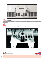
1. Il funzionamento della barriera d’aria in modalità riscaldante,nel periodo invernale, può essere continuativo
2. Nel caso di funzionamenti anomali della barriera d’aria spegnere l’apparecchio e farlo controllare da un tecnico specializzato.
3. Non utilizzare la barriera d’aria in modalità riscaldamento quando la ventola è spenta.
4. Pulire regolarmente la barriera e tutti gli accessori.
5. Mantenere la distanza minima per permettere il collegamento elettrico dal soffitto
6. Installare solo in ambienti interni.
7. Installare solo orizzontalmente.
8. Installare ad almeno 2 mt dal suolo.
9. Per motivi di sicurezza installare la barriera d’aria su un supporto stabile per evitare vibrazioni.
L’altezza di installazione deve essere almeno di 2 metri.
10. Nel caso di porte molto larghe è possibile affiancare più unità.
11. Non montare all’interno di intercapedini.
12. Consultate del personale qualificato prima dell’installazione.
1. The operation of the air curtain in heating mode, in the winter period, can be ongoing
2. In case of anomalous functioning of the air barrier, switch off the appliance and have it checked by a specialized technician.
3. Do not use the air curtain in heating mode when the fan is off.
4. Clean the barrier and all accessories regularly.
5. Maintain the minimum distance to allow electrical connection from the ceiling
6. Install indoors only.
7. Install only horizontally.
8. Install at least 2 meters above the ground.
9. For safety reasons, install the air curtain on a stable support to avoid vibrations.
The installation height must be at least 2 meters.
10. In the case of very large doors, it is possible to combine several units.
11. Do not mount inside cavities.
12. Consult qualified personnel before installation.
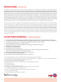
Le barriere d’aria Tecnosystemi sono state studiate e realizzate per permettere di ottimizzare la resa degli impianti di
climatizzazione dei locali in cui viene installata, compatibilmente con la necessità da parte degli utenti di accedere ed uscire
dai locali spesso in modo continuativo, evitando così di aprire e chiudere continuamente le porte, permettendo un notevole
risparmio economico, e riducendo quasi a zero la dispersione termica. La barriera d’aria, posizionata internamente sopra la
porta d’ingresso, genera un flusso d’aria che spinto velocemente verso il basso, crea una netta separazione tra il volume
d’aria interna e quella esterna, permettendo così di climatizzare correttamente gli ambienti senza alcuna dispersione,
sia nella stagione estiva che in quella invernale. Altri vantaggi sono determinati dalla notevole riduzione di consumo
energetico e dall’impedimento dell’entrata di gas di scarico e polvere anche a porte aperte all’interno dei locali. L’ottimale
utilizzo della barriera d’aria è reso possibile dalle tre differenti velocità del motore regolabili tramite telecomando.
Tecnosystemi’s air curtains are designed and built to optimise the performance of air-conditioning systems in the rooms in which
they are installed, in such a way that they do interfere with users need to go in and out of those rooms, often continuously, without
having to constantly open and close the doors. This guarantees considerable financial savings, by significantly reducing heat loss.
The air curtain positioned above the door on the inside of the room, generates an air flow that is rapidly forced downwards, creating
a clear separation between the volumes of internal and external air, thus enabling the rooms to be properly air-conditioned, with
no heat loss in winter and no over-heating in summer. Other benefits derive from the significant reduction in energy consumption,
and from the fact that the system prevents exhaust fumes, dust and insects coming in even when the doors inside the premises
are open. The optimal utilisation of the air curtain is guaranteed by the three different motor speeds, which can be regulated using
the remote control device.
DESCRIZIONE / DESCRIPTION
AVVERTENZE GENERALI / GENERAL WARNINGS

3
ATTENZIONE! / WARNING!
Non infilare le dita o qualsiasi altro oggetto nell’ apertura di uscita o di entrata dell’aria ad apparecchio fermo, o
durante il funzionamento, in quanto c’è la possibilità di ferirsi. Se durante la normale marcia la barriera si blocca, non
cercare di farla ripartire agendo manualmente sulla ventola perché c’è la possibilità di ferirsi o di scariche elettriche,
far controllare da personale qualificato. E’ vietato manipolare il prodotto per apportare delle modifiche, o verificare
anomalie di funzionamento. Per le riparazioni rivolgersi sempre ad un tecnico specializzato o al centro assistenza.
/
Do not put your fingers or any other object into the air discharge or intake aperture, while the machine is either stationary or
operating, as you risk injuring yourself by doing so. If, during normal working, the curtain stops, do not try to get it going again
by manually intervening with regard to the fan as this could lead to injury or electric shock; have the unit controlled by qualified
personnel. It is forbidden to handle the product in order to make any modifications, or to check any anomalies in its functioning.
Repairs should always be carried out by a specialised engineer or by the customer service centre.
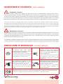
AVVERTENZE DI SICUREZZA / SAFETY WARNINGS
IMPORTANTE! / IMPORTANT!
E’ vietato lavare la barriera con getti d’acqua o versandoci sopra prodotti liquidi, potrebbero provocare corto circuiti.
Prima di effettuare qualsiasi operazione sulla barriera staccare la spina dalla presa di alimentazione. Non utilizzare
il prodotta nelle stanze da bagno o in altri ambienti dove ci sia un’ umidità elevata o in presenza di spruzzi d’acqua.
(Grado di protezione della barriera IP 20).
/ It is forbidden to wash the curtain with jets of water, or by pouring liquids over it, as this could cause short circuiting. Before
carrying out any operation involving the curtain, remove the plug from the electrical socket. Do not utilise the product in bathrooms
or in any other rooms characterised by high humidity or the presence of water sprays. (Degree of protection of the IP 20 curtain).
La barriera d’aria deve essere
scollegata dalla rete elettrica prima di
ogni installazione o riparazione.
/ The air curtain must be disconnected
from the mains supply before carrying out
any installation or repair operation.
Non posizionare radiatori o altri
dispositivi in prossimità del cavo di
alimentazione della barriera d’aria.
/ Do not place any radiators or other
devices near the power cord of the air
curtain.
Non utilizzare apparecchiature o conduttori danneggiati per collegare la barriera d’aria alla rete.
/ Do not use damaged equipment or wires to connect the air curtain to the mains.
Nell’installare la barriera d’aria, seguire
le normative di sicurezza specifiche per
le apparecchiature elettriche.
/ When installing the air curtain, follow
the specific safety regulations for
electrical equipment.
La barriera d’aria non deve essere
utilizzata al di fuori della gamma di
temperatura indicata nel manuale
d’uso o in atmosfere aggressive o a
rischio di esplosione.
/ The air curtain must not be used beyond
the temperature range, shown in the
user manual or in aggressive or explosive
atmospheres.
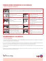
PRECAUZIONI DI MONTAGGIO / ASSEMBLY WARNINGS

4
Non lavare la barriera d’aria con acqua. Proteggere le parti elettriche del ventilatore dall’ingresso di acqua.
/ Do not wash the air curtain with water. Protect the electrical parts of the fan from water seepage.
Staccare la barriera d’aria dalla rete
prima della manutenzione.
/ Disconnect the air curtain from the
mains before maintenance.
Non danneggiare il cavo di
alimentazione durante l’utilizzo della
barriera d’aria. Non mettere oggetti sul
cavo di alimentazione.
/ Do not damage the power cord when
using the air curtain. Do not place objects
on the power cord.
Non aprire la barriera d’aria in funzione.
/ Do not open the air curtain when it is on.
Non lasciare che l’aria in uscita dalla
barriera d’aria punti su fiamme aperte
o candele.
/ Make sure that the air emitted by the
air curtain is not directed at naked flames
or candles.
Non bloccare il condotto aria quando la
barriera d’aria è accesa.
/ Do not block the air duct when the air
curtain is on.
Impedire ai bambini di utilizzare la
barriera d’aria.
/ Do not let children use the air curtain.
Tenere prodotti esplosivi ed infiammabili
lontano dalla barriera d’aria.
/ Keep explosive and flammable products
away from the heat air curtain.
In caso di rumori insoliti, fumo, staccare
la barriera d’aria dalla presa di corrente
e contattare il servizio clienti.
/ In case of unusual noises or smoke,
disconnect the air curtain from the wall
outlet and contact customer service.
PRECAUZIONI OPERATIVE DI SICUREZZA
/ SAFETY OPERATING WARNINGS
1) Al termine dell’installazione elettrica il cavo di alimentazione deve essere fissato con fascette per impedire il
contatto con le griglie calde di entrata dell’aria.
2) In caso di mancato riscaldamento dell’aria occorre far controllare da un tecnico qualificato l’apparecchio per
accertare la causa d’intervento dei dispositivi di sicurezza (termostati o riarmo manuale interni).
1) At the end of the electrical installation the power supply cable must be fixed with clamps to prevent contact with the hot
air intake grilles.
2) If the air is not heated, a qualified technician should have the appliance checked to ascertain the cause of the safety
devices (internal thermostats or manual reset).
AVVERTENZE DI SICUREZZA
/ SAFETY WARNINGS
A C
25
B

5
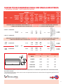
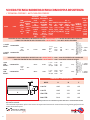
*La temperatura indicata è riferita all' aumento di temperatura tra l'ambiente e quella dell'aria in uscita dalla barriera
alla minima velocità.
*The indicated temperature refers to the increase in temperature between the room and the air being discharged from the air
curtain at minimum speed.
MOD. COD.
TENSIONE
ALIMENT.
/ SUPPLY
VOLTAGE
POTENZA
ASSOR-
BITA
/ ABSOR-
BED
POWER
[W]
POTENZA
ASSORBITA
CON
RESI-
STENZA /
ABSORBED
POWER
WITH
RESISTANCE
[W]
VEL.ARIA
ALLA
BOCCA
/ AIR
SPEED
AT THE
INTAKE
[m/s]
PORTA-
TA
ARIA
/ AIR
FLOW
[m
3
/h]
LIVELLO
SONORO
/ SOUND
LEVEL
[dB (A)]
Ø t °C
ARIA
CON
RESI-
STENZA
/ AIR
SPEED
AT THE
INTAK
PESO
/
WEI-
GHT
[kg]
TELECO-
MANDO
/ REMOTE
CONTROL
DEVICE
ADATTA
PER
PORTE
/ ENTRAN-
CES
WITH
DIMEN-
SIONS
[mm]
BARRIERE D’ARIA TANGENZIALI MONOVENTOLA CON 1 RESISTENZA L: 1100 AD ASPIRAZIONE SUPERIORE
/ SINGLE-FAN TANGENTIAL AIR CURTAINS WITH 1 RESISTANCE L: 1100 WITH UPPER AIR INTAKE
1100 DX 12300050RI
230 Vac
50 Hz 75 1900 I: 7,5
II: 8
III: 9
693
738
783
65
67
68 12°* 14,8
Regolazione 3 velocità
e ON/OFF Resistenza
/ ADJUSTMENT
3 SPEED AND ON/OFF
RESISTANCE
L 1000
H 3000
1100 SX 12300051RI
BARRIERE D’ARIA TANGENZIALI BIVENTOLA CON 2 RESISTENZE L: 1500 - 2000 AD ASPIRAZIONE SUPERIORE
/ DUAL-FAN TANGENTIAL AIR CURTAINS WITH 2 RESISTANCE L: 1500 - 2000 WITH UPPER AIR INTAKE
1500
CEN. 12300055RI
230 Vac
50 Hz 190
3200 I: 7,5
II: 8
III: 9
1161
1188
1215
68
68,5
69
12°*
21,4
Regolazione 3 velocità e
ON/OFF Resistenza
/ ADJUSTMENT
3 SPEED AND ON/OFF RESI-
STANCE
L 1500
H 3000
2000
CEN. 12300056RI
3800 I: 7,5
II: 8
III: 9
1332
1404
1458
67
68
70 28,6 L 2000
H 3000
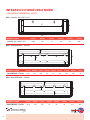
DIMENSIONI / DIMENSIONS [mm]
MOD. A B C
1100 DX 1085 250 185
1100 SX 1085 250 185
1500 CEN. 1440 250 185
2000 CEN. 2040 250 185
SCHEDA TECNICA BARRIERA D’ARIA CON SINGOLA RESISTENZA
/ TECHNICAL FEATURES - WITH ONE RESISTANCES
A C
25
B

6
SCHEDA TECNICA BARRIERA D’ARIA CON DOPPIA RESISTENZA
/ TECHNICAL FEATURES - WITH TWO RESISTANCES
*La temperatura indicata è riferita all' aumento di temperatura tra l'ambiente e quella dell'aria in uscita dalla barriera
alla minima velocità.
*The indicated temperature refers to the increase in temperature between the room and the air being discharged from the air
curtain at minimum speed.
DIMENSIONI / DIMENSIONS [mm]
MOD. A B C
1100 DX 1085 250 185
1100 SX 1085 250 185
1500 CEN. 1440 250 185
2000 CEN. 2040 250 185
MOD. COD.
TEN-
SIONE
ALI-
MENT.
/ SUP-
PLY
VOLTA-
GE
POTENZA
ASSOR-
BITA
/ ABSOR-
BED
POWER
[W]
POTENZA
ASSORBITA
CON
RESISTEN-
ZA
½ CARICO
/ ABSORBED
POWER
WITH
RESIST.
½ LOAD
[W]
POTENZA
ASSORBITA
CON
RESISTEN-
ZA PIENO
CARICO
/ ABSORBED
POWER
WITH
RESIST.
FULL LOAD
[W]
VEL.
ARIA
ALLA
BOC-
CA
/ AIR
SPEED
AT THE
INTAKE
[m/s]
PORTA-
TA
ARIA
/ AIR
FLOW
[m
3
/h]
LIVELLO
SONO-
RO
/ SOUND
LEVEL
[dB (A)]
Ø t °C
ARIA CON
RESI-
STENZA
/ AIR
SPEED
AT THE
INTAK
PESO
/ WEI-
GHT
[kg]
TELECO-
MANDO
/ REMOTE
CONTROL
DEVICE
ADATTA
PER
PORTE
/ EN-
TRAN-
CES
WITH
DIMEN-
SIONS
[mm]
BARRIERE D’ARIA TANGENZIALI MONOVENTOLA CON 2 RESISTENZE L: 1100 AD ASPIRAZIONE SUPERIORE
/ SINGLE-FAN TANGENTIAL AIR CURTAINS WITH 2 RESISTANCES L: 1100 WITH UPPER AIR INTAKE
1100 DX
RESIST. 12300050RI2
230
Vac
50 Hz 75 1900 3800
I: 7,5
II: 8
III:
8,5
675
720
738
64
65
66 25°* 15,7
Regolazione 3 velocità
e ON/OFF Resistenza
/ ADJUSTMENT
3 SPEED AND ON/OFF
RESISTANCE
L 1000
H
3000
1100 SX
RESIST. 12300051RI2
BARRIERE D’ARIA TANGENZIALI BIVENTOLA CON 4 RESISTENZE L: 1500 - 2000 AD ASPIRAZIONE SUPERIORE
/ DUAL-FAN TANGENTIAL AIR CURTAINS WITH 4 RESISTANCES L: 1500 - 2000 WITH UPPER AIR INTAKE
1500
CEN.
RESIST.
12300055RI2
400
Vac
50 Hz 190
3200 6400
I: 7,5
II: 8
III: 8,5
1134
1174
1188
66
67
67
25°*
22,3
Regolazione 3 velocità e
ON/OFF Resistenza
/ ADJUSTMENT
3 SPEED AND ON/OFF
RESISTANCE
L 1500
H 3000
2000
CEN.
RESIST.
12300056RI2
3800 7600
I: 7,5
II: 8
III: 8,5
1242
1278
1332
66,5
67
70 29,6 L 2000
H 3000
A C
25
B

7
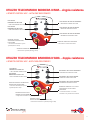
ON
MODE
OFF
PULSANTE
BARRIERA D’ARIA ON
/ AIR CURTAIN ON BUTTON PULSANTE VELOCITA’ MASSIMA
/ MAXIMUM SPEED BUTTON
PULSANTE VELOCITA’ MEDIA
/ MEDIUM SPEED BUTTON
PULSANTE VELOCITA’ MINIMA
/ MINIMUM SPEED BUTTON
PULSANTE
BARRIERA D’ARIA OFF
/ AIR CURTAIN OFF BUTTON
Simbolo velocita’ ventilazione
selezionata (Led verde)
/ Selected ventilation speed
symbol (Green LED) Pulsante selezione 1/2 carico
resistenza o carico intero
resistenza
/ Selection button 1/2 load
resistance or full load resistance
Simbolo mezzo carico
resistenza (Led giallo)
/ Half load resistance symbol (yellow LED)
Simbolo carico
intero resistenza (Led arancione)
/ Full load resistance symbol (orange LED)
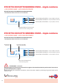
UTILIZZO TELECOMANDO BARRIERA D’ARIA - doppia resistenza
/ REMOTE CONTROL USE - WITH TWO RESISTANCES
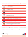
UTILIZZO TELECOMANDO BARRIERA D’ARIA - singola resistenza
/ REMOTE CONTROL USE - WITH ONE RESISTANCES
ON
MODE
OFF
PULSANTE
BARRIERA D’ARIA ON
/ AIR CURTAIN ON BUTTON
PULSANTE VELOCITA’ MASSIMA
/ MAXIMUM SPEED BUTTON
PULSANTE VELOCITA’ MEDIA
/ MEDIUM SPEED BUTTON
PULSANTE VELOCITA’ MINIMA
/ MINIMUM SPEED BUTTON
PULSANTE
BARRIERA D’ARIA OFF
/ AIR CURTAIN OFF BUTTON
Simbolo velocita’
ventilazione selezionata
(Led verde)
/ Selected ventilation speed
symbol (Green LED)
Pulsante selezione resistenza
/ Resistance selection button
Simbolo resistenza (Led arancione)
/ Resistance symbol (Orange LED)

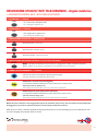
8
1. ACCENSIONE / 1. TURN ON
- On / accensione dell’apparecchio
- On / turning the appliance on
2. SPEGNIMENTO / 2. TURN OFF
- Off/ spegnimento apparecchio
- Off / turning the appliance off
3. IMPOSTAZIONE DI VELOCITÀ / 3. SPEED SETTING
Velocità minima / Low speed
Velocità media / Medium speed
Velocità massima
/ Maximum speed
4. IMPOSTAZIONE RESISTENZA ELETTRICA
/ SET ELECTRICAL RESISTANCE
MODE - Permette di selezionare l’accensione e lo spegnimento delle resistenze elettriche
MODE - Allows you to select the switching on and off of the electric resistances
5. SIMBOLI DI FUNZIONAMENTO
/ 4. SYMBOLS
Indicazione velocita’ ventilazione selezionata (Led verde)
Indication of selected ventilation speed (green LED)
Resistenza elettrica (icona colore arancione)
Le resistenze installate nella barriera d’aria funzionano a pieno carico
Electric resistances (orange icon)
The heating elements installed in the air curtain operate at full load
ON
OFF
MODE
DESCRIZIONE UTILIZZO TASTI TELECOMANDO - singola resistenza
/ USE REMOTE CONTROL KEYS - WITH ONE RESISTANCE
NOTA: Nel caso la barriera d’aria venga spenta mentre le resistenze sono accese, i led che indicano la velocità dell’aria,
lampeggeranno per 240 sec. prima di arrestare il funzionamento della barriera d’aria.
NOTE: If the air curtain is switched off while the heating elements are on, the leds indicating the air speed will flash for 240
sec. before stopping the operation of the air curtain.

9
NOTA: Nel caso la barriera d’aria venga spenta mentre le resistenze sono accese, i led che indicano la velocità dell’aria,
lampeggeranno per 240 sec. prima di arrestare il funzionamento della barriera d’aria.
NOTE: If the air curtain is switched off while the heating elements are on, the leds indicating the air speed will flash for 240
sec. before stopping the operation of the air curtain.
1. ACCENSIONE / 1. TURN ON
- On / accensione dell’apparecchio
- On / turning the appliance on
2. SPEGNIMENTO / 2. TURN OFF
- Off/ spegnimento apparecchio
- Off / turning the appliance off
3. IMPOSTAZIONE DI VELOCITÀ / 3. SPEED SETTING
Velocità minima / Low speed
Velocità media / Medium speed
Velocità massima
/ Maximum speed
4. IMPOSTAZIONE RESISTENZA ELETTRICA
/ SET ELECTRICAL RESISTANCE
MODE - Permette di selezionare l’accensione e lo spegnimento delle resistenze elettriche
MODE - Allows you to select the switching on and off of the electric resistances
5. SIMBOLI DI FUNZIONAMENTO
/ 4. SYMBOLS
Indicazione velocita’ ventilazione selezionata (Led verde)
Selected ventilation speed indicator (green LED)
Resistenza 1/2 carico (icona colore giallo)
Le resistenze installate nella barriera d’aria funzionano a mezzo carico
Half load resistance (yellow icon)
The heating elements installed in the air curtain work at half load
Resistenza pieno carico (icona colore arancione)
Le resistenze installate nella barriera d’aria funzionano a pieno carico
Full load resistor (orange icon)
The heating elements installed in the air curtain operate at full load
ON
OFF
MODE
DESCRIZIONE UTILIZZO TASTI TELECOMANDO - doppia resistenza
/ USE REMOTE CONTROL KEYS - WITH TWO RESISTANCES

10
/ Electrical resistance (Orange LED)
ETICHETTA CRUSCOTTO MONTATA A BORDO MACCHINA
/ DASHBOARD LABEL INSTALLED ON THE MACHINE
ETICHETTA CRUSCOTTO MONTATA A BORDO MACCHINA
/ DASHBOARD LABEL INSTALLED ON THE MACHINE
Resistenza Elettrica (Led arancione)
ATTENZIONE! / WARNING!
Prima di eseguire le operazioni di manutenzione togliere l’alimentazione elettrica posizionando l’interruttore
generale dell’impianto su “spento.
Before performing the maintenance operations, remove the power supply by positioning the general switch of the
system on “off”.
ETICHETTA CRUSCOTTO BARRIERA D’ARIA - singola resistenza
/ AIR CURTAINS LABEL - WITH ONE RESISTANCES
ETICHETTA CRUSCOTTO BARRIERA D’ARIA - doppia resistenza
/ AIR CURTAINS LABEL - WITH TWO RESISTANCES
3° velocita’ (Max) 3 LED ACCESI / 3rd speed (Max) 3 LEDs ON
2° velocita’ (Med) 2 LED ACCESI / 2nd speed (Med) 2 LEDs ON
1° velocita’ (Min) 1 LED ACCESO / 1st speed (Min) 1 LED ON
3° velocita’ (Max) 3 LED ACCESI / 3rd speed (Max) 3 LEDs ON
2° velocita’ (Med) 2 LED ACCESI / 2nd speed (Med) 2 LEDs ON
1° velocita’ (Min) 1 LED ACCESO / 1st speed (Min) 1 LED ON
/ Full load (orange LED)
Pieno Carico (Led arancione)
/ Half load (yellow LED)/ IR Receiver
1/2 Carico (Led giallo)Ricevitore IR

11
ATTENZIONE! / IMPORTANT!
Prima di effettuare la messa in opera della barriera d’aria assicurarsi che la stessa non sia collegata alla rete
elettrica, ed indossare i guanti in gomma di protezione.
Before carrying out the installation of the air barrier, make sure that it is not connected to the mains, and wear
protective rubber gloves.
IMPORTANTE! / WARNING!
Importante! L’installazione delle barriere deve essere eseguita da personale qualificato e in accordo alla
norma cei 64.8. (Collegamento elettrico), e secondo questo manuale.
The curtain must be installed by qualified personnel, and in compliance with the IEC 64.8 standard. (Electrical
connections), and according to this manual.
Le barriere d’aria Tecnosystemi possono essere installate sopra la porta, posizionandola in modo che la bocca della bar-
riera sia centrata con l’apertura dell’ingresso. La barriera non deve mai essere installata all’esterno della porta o in luogo
esposto alle intemperie (pioggia…vento…). Assicurarsi che in nessun modo possa venire a contatto con pioggia, o aspiri
acqua perché potrebbero esserci problemi di cortocircuito. E’ obbligatorio il fissaggio della barriera alla muratura tramite
i fori realizzati sulla schiena. Rimane responsabilità dell’installatore scegliere il tipo di fissaggio più idoneo per il tipo di
muratura sulla quale verrà applicata la barriera. Bisogna che sia sempre lasciato uno spazio di almeno 15 cm. tra la griglia
di protezione superiore e il soffitto del locale, per permettere alla barriera di aspirare aria; e non ostruire con teli o pannelli
ad incasso. Ogni macchina viene venduta completa di spina di alimentazione e di telecomando.
Tecnosystemi air curtains can be installed above doors, at a minimum height of 1.8 m. above the floor, and must be positioned
in such a way that the curtain’s opening is positioned centrally vis-à-vis the door opening. The curtain must never be installed
outside of the door, or anywhere exposed to the elements (rain, wind, etc.). Ensure that it cannot come into contact with rain, or
suck in water, as this could cause short-circuiting. The air curtain must be fastened to the wall using the holes positioned on the
back. The installation engineer shall be responsible for choosing the most suitable type of fastening for the specific wall to which
the curtain is to be fixed. A gap of about 15 cm. Must always be left between the upper protective grill and the ceiling, in order
to enable the curtain to take in air. Do not obstruct with sheets or built-in panels, and do not position the curtain immediately
beneath an electrical socket. Each machine is sold complete with a fitted plug and a remote control device.
NON INSTALLARE la barriera d’aria nelle seguenti condizioni:
1. Assicurarsi che in nessun modo possa venire a contatto con pioggia, o aspiri acqua perché queste condizioni potrebbero
essere causa di cortocircuiti.
2. In presenza di vapori infiammabili.
3. Temperatura superiore a +40°C o inferiore a -10°C.; umidità relativa ≥90%.
4. In presenza di miscele esplosive o in presenza di gas.
5. Umidità relativa superiore al 90%.
INSTALLAZIONE E MESSA IN OPERA
/ INSTALLATION AND COMMISSIONING
DO NOT INSTALL the air curtain in the following conditions:
1. Make sure that it can in no way come into contact with rain, or draw water because these conditions could cause a short circuit.
2. In the presence of flammable vapors.
3. Temperature above + 40 ° C or below -10 ° C; relative humidity ≥90%.
4. In the presence of explosive mixtures or in the presence of gas.
5. Relative humidity higher than 90%.
CONDIZIONI DI UTILIZZO / CONDITIONS OF USE

12
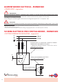
IMPORTANT!
during the electrical connection, the installer must respect the polarities indicated by the plate placed in front of the
power terminal board:
- L (connect the line conductor: internally all the safety protections are inserted)
- N (connect the neutral connector)
- Earth (connect the yellow green conductor having a length greater than 1 cm with respect to L and N).
IMPORTANTE!
durante il collegamento elettrico, l’installatore deve rispettare le polarità indicate dalla targhetta posta davanti
alla morsettiera di alimentazione:
-L (collegare il conduttore di linea: internamente risultano inserite tutte le protezioni di sicurezza)
-N (collegare il connettore di neutro)
-Terra (collegare il conduttore giallo verde avente una lunghezza superiore di 1 cm rispetto L e N).
L
N
230 V
50 Hz
L
N
INTERRUTTORE DI PROTEZIONE MAGNETO-TERMICA
ONNIPOLARE CONFORME A EN 61508:1
/ ONNIPOLAR MAGNETOTHERMAL PROTECTION SWITCH
COMPLIANT A EN 61508: 1
SCATOLA COLLEGAMENTO ELETTRICO
/ ELECTRICAL CONNECTION BOX
CAVO DI ALIMENTAZIONE
/ POWER CORD
3 x 2,5 MMQ>HAR<
0
1
T3A T3A
ALIMENTAZIONE ELETTRICA - MONOFASE
/ POWER SUPPLY - single phase
SCHEMA ELETTRICO PER L’INSTALLAZIONE - MONOFASE
/ ELECTRICAL DIAGRAM FOR INSTALLATION - single phase

13
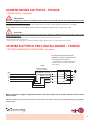
IMPORTANTE!
Durante il collegamento elettrico, l’installatore deve rispettare le polarità indicate dalla targhetta posta davanti
alla morsettiera di alimentazione:
-L1-L2-L3 (collegare il conduttore di linea: internamente risultano inserite tutte le protezioni di sicurezza)
-N (collegare il connettore di neutro)
-Terra (collegare il conduttore giallo verde avente una lunghezza superiore di 1 cm rispetto L e N).
INTERRUTTORE DI PROTEZIONE
MAGNETO-TERMICA ONNIPOLARE
CONFORME A EN 61508:1
/ OMNIPOLAR THERMAL-MAGNETIC
CIRCUIT BREAKER COMPLAINT WITH
EN 61508:1
NOTA: è necessario collegare il disgiuntore termico, dei motori elettrici ad un sistema ausiliario di interruzione
trifase esterno.
V 400
GIALLO/VERDE
YELLOW / GREEN
MARRONE / BROWN
NERO / BLACK
BIANCO/WHITE
BLU/BLUE
L1
L1
GN
L2L2
L3
N
L3
N
IMPORTANT!
during the electrical connection, the installer must respect the polarities indicated by the plate placed in front of the
power terminal board:
-L1-L2-L3 (connect the line conductor: internally all the safety protections are inserted)
- N (connect the neutral connector)
- Earth (connect the yellow green conductor having a length greater than 1 cm with respect to L and N).
NOTE: it is necessary to connect the thermal circuit breaker of the electric motors to an external auxiliary hold-off three-
phase system.
ALIMENTAZIONE ELETTRICA - TRIFASE
/ POWER SUPPLY - tree phase
SCHEMA ELETTRICO PER L’INSTALLAZIONE - TRIFASE
/ ELECTRICAL DIAGRAM FOR INSTALLATION - tree phase

14
MOD.: 2000 CENTRALE / CENTRAL
MOD.: 1500 CENTRALE / CENTRAL
MODELLO / MODEL A [mm] B [mm] C [mm] D [mm] E [mm] F [mm] G [mm] H [mm] I [mm]
1500 CENTRALE / CENTRAL
1435 255 185 65 70 160 565 130 35
MOD.: 1100 DX - SX / RIGHT - LEFT
MODELLO / MODEL A [mm] B [mm] C [mm] D [mm] E [mm] F [mm]
1100 DX - SX / RIGHT - LEFT
1080 255 25 50 35 980
A
F
B
C
E
D
E G GF
H
D
E
I
B
A
C
E E B
F
A
G
C
GHG
D
G
MODELLO / MODEL A [mm] B [mm] C [mm] D [mm] E [mm] F [mm] G [mm] H [mm]
2000 CENTRALE / CENTRAL
2010 250 166 70 50 50 270 130
INTERASSI DI FORATURA A MURO
/ DISTANCE BETWEEN WALL HOLES

15
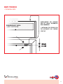
IMPOSTAZIONE DELLE MODALITÀ’ DI FUNZIONAMENTO DELLA BARRIERA D’ARIA CON “KIT AVVIO AUTOMATICO”
(optional)
Collegare il sensore dotato di cavetto alla barriera d’aria mediante jack, fissare il sensore magnetico A alla cassa
della porta o in un punto solido con il telaio del serramento. Fissare il secondo sensore alla parte mobile dell’infisso
lasciando uno spazio massimo tra i due sensori di circa 2 cm.
Con l’installazione del “kit avvio automatico” la barriera ha la possibilità di operare in due differenti modalità di
funzionamento:
MODALITÀ 1
La barriera funziona solamente alla massima velocità escludendo totalmente l’utilizzo del telecomando e delle
resistenze elettriche.
Esempio;
Porta chiusa, barriera in stand-by (nessuna velocità e resistenza elettrica attiva).
Apro la porta, la velocità passa al valore massimo e la resistenza elettrica rimane disattiva.
Chiudo la porta, la barriera ritorna in stand-by.
Per attivare questa modalità di funzionamento procedere come segue:
1. Premere il pulsante ON
2. Scollegare il jack
3. Premere il pulsante ON
4. Il led arancione si accenderà
5. Premere il pulsante ON
6. Il led arancione si spegnerà
7. Ricollegare il jack
Nota: la barriera viene consegnata, di serie, con modalità 1 attiva.
MODALITÀ 2
In questa modalità è possibile selezionare, tramite il telecomando, sia il funzionamento delle velocità che delle
resistenze elettriche.
Esempio;
Seleziono velocità minima e la resistenza elettrica.
Apro la porta, la velocità passa al valore massimo e la resistenza elettrica rimane attiva.
Chiudo la porta, la barriera ritorna alla velocità minima con resistenza elettrica attiva.
Per attivare questa modalità di funzionamento procedere come segue:
1. Premere il pulsante ON
2. Scollegare il jack
3. Premere il pulsante ON
4. Il led arancione si accenderà
5. Ricollegare il jack
INSTALLAZIONE
/ INSTALLATION
Questo kit venduto separatamente alla barriera d’aria permette di collegare direttamente l’accensione e lo
spegnimento della macchina con l’apertura e la chiusura della porta.
This kit, sold separately from the air curtain, allows you to switch the machine on and off by opening and closing the door.
KIT AVVIO AUTOMATICO PER BARRIERA D’ARIA
/ AUTOMATIC KIT START

16
AIR CURTAIN OPERATING MODES SETTINGS WITH “AUTOMATIC START KIT” (optional)
Connect the sensor with cable to the air curtain by means of a jack and attach magnetic sensor A to the door casing or in
any case to something firmly secured to the frame. Attach the second sensor to the moving part of the door leaving no more
than 2 cm between the two sensors.
When the “automatic start kit” is installed, the air curtain can have two different operating modes
MODE 1
The air curtain works at maximum speed only, completely excluding the use of the remote control and of the heating elements.
Example. Door closed, air curtain in stand-by (no speed and heating element active).
When the door is opened, the speed reaches the maximum value and the heating element remains deactivated. When the
door is closed, the air curtain goes back in stand-by.
To activate this operating mode, proceed as follows:
1. Press the ON button
2. Disconnect the jack
3. Press the ON button
4. The orange LED will turn on
5. Press the ON button
6. The orange LED will turn off
7. Reconnect the jack
Note: the air curtain is delivered, as standard, with mode 1 active.
MODE 2
In this mode it is possible to select, using the remote control, both the operation of the speeds and of the heating elements.
Example. Select the minimum speed and the heating element.
When the door is opened, the speed reaches the maximum value and the heating element remains active. When the door
is closed, the air curtain goes back to the minimum speed with the heating element active. To activate this operating mode,
proceed as follows:
1. Press the ON button
2. Disconnect the jack
3. Press the ON button
4. The orange LED will turn on
5. Reconnect the jack

17
DATI TECNICI
/ TECHNICAL DATA
BARRIERA D’ARIA
/ AIR CURTAINS
INSTALLAZIONE DEL SENSORE
PER KIT AVVIO AUTOMATICO
DELLA BARRIERA.
/ INSTALLING THE SENSOR FOR
THE AUTOMATIC AIR CURTAIN
START KIT

18
Alimentare la batteria utilizzando il cavo elettrico idoneo come da istruzioni. Power the battery using the
appropriate electric cable as instructed.
Power the battery using the appropriate electric cable as instructed.
ATTENZIONE!
Prima di dare tensione assicurarsi che il jack nero sia inserito - Installare il pressacavo per collegare l’alimentazione
come da figura.
WARNING!
Prior to switching on, ensure that the jack is plugged in Install the cable gland to connect the power supply as in the figure.

19
Le barriere d’aria non necessitano di particolare manutenzione. Per la pulizia esterna utilizzare un detergente neutro
con un panno umido per rimuovere la polvere, ed utilizzare un panno asciutto per eliminare i residui. Effettuare una
soffiatura con aria compressa dirigendo il getto verso la ventola e il vano motore per rimuovere la polvere depositata.
Il numero di interventi va effettuato in funzione dell’utilizzo del prodotto, si consiglia comunque un controllo ogni 2/3
mesi e di effettuare una prova di funzionamento ad ogni inizio di stagione.
Air curtains do not require any special maintenance. For external cleaning, use a neutral detergent with a damp cloth to remove
dust and use a dry cloth to eliminate any residual dust. Blow compressed air by aiming the jet at the fan and motor compartment
to remove any dust deposits. The number of interventions should be based on the use of the air curtain. It is, however, advisable
to carry out a check every 2/3 months and to do a test run at the beginning of each season.
PULIZIA E CONTROLLI E MANUTENZIONE
/ CLEANING AND CHECKS

20
SMALTIMENTO
DISPOSAL
GARANZIA
WARRANTY
Alla fine della sua vita utile il prodotto non deve essere smaltito insieme ai rifiuti urbani. Può essere
consegnato presso gli appositi centri di raccolta differenziata predisposti dalle amministrazioni
comunali, oppure presso i rivenditori che forniscono questo servizio. Per rimarcare l’obbligo di smaltire
separatamente gli elettrodomestici, sul prodotto è riportato il marchio del contenitore di spazzatura
mobile barrato.
At the end of its useful life, the product must not be disposed of with household waste. It can be deposited at
a dedicated recycling centre run by local councils, or at retailers who provide such a service. To highlight the
requirement to dispose of household electrical items separately, there is a crossed-out waste paper basket
symbol on the product.
La garanzia ha durata di 1 (uno) anno a decorrere dalla data di consegna indicata sul d.d.t (bolla). E’ prevista altresì
l’estensione d’ufficio, a titolo gratuito, per il secondo anno (due anni complessivi di garanzia) con decorrenza sempre
dalla data indicata nel d.d.t di consegna (bolla).
L’azienda fornitrice garantisce la qualità dei materiali impiegati e la corretta realizzazione dei componenti. La garanzia
copre difetti di materiale e di fabbricazione e si intende relativa alla fornitura dei pezzi in sostituzione di qualsiasi
componente che presenti difetti, senza che possa venir reclamata alcuna indennità, interesse o richiesta di danni.
La garanzia non copre la sostituzione dei componenti che risultano danneggiati per:
• trasporto non idoneo;
• installazione non conforme a quanto specificato in questo manuale di installazione uso e manutenzione;
• la non osservanza delle specifiche tecniche di prodotto;
• quant’altro non riconducibile a vizi originari del materiale o di produzione a condizione che il reclamo del cliente
sia coperto dalla garanzia e notificato nei termini e modalità richiesta dal fornitore, lo stesso si impegnerà, a sua
discrezione, a sostituire o riparare ciascun prodotto o le parti di questo che presentino vizi o difetti.
The warranty is valid for 2 (two) years from the delivery date indicated on the delivery note / waybill.
The supplier company guarantees the quality of the materials used and the correct construction of the components. The
warranty covers defects in materials and manufacturing defects and refers to the supply of spare parts of any components
featuring defects, without any compensation, interest or claim for damages.
The warranty does not cover the replacement of components damaged due to:
incorrect transportation;
installation not compliant with that specified in this installation, use and maintenance manual;
non-observance of product technical specifications;
Anything else that is not linked to original faults of the material or production provided that the
customer complaint is covered by the guarantee and a claim is made within the time limit and
in the way requested by the supplier, the same supplier will commit, at their own discretion,
to replace or repair any product or part of product showing signs of faults or defects.
La pagina si sta caricando...
La pagina si sta caricando...
La pagina si sta caricando...
La pagina si sta caricando...
-
 1
1
-
 2
2
-
 3
3
-
 4
4
-
 5
5
-
 6
6
-
 7
7
-
 8
8
-
 9
9
-
 10
10
-
 11
11
-
 12
12
-
 13
13
-
 14
14
-
 15
15
-
 16
16
-
 17
17
-
 18
18
-
 19
19
-
 20
20
-
 21
21
-
 22
22
-
 23
23
-
 24
24


Tecnosystemi 12300055RI2 Manuale utente
- Tipo
- Manuale utente
- Questo manuale è adatto anche per
in altre lingue
- English: Tecnosystemi 12300055RI2 User manual
Documenti correlati
-
Tecnosystemi Built-in tangential air curtain at room temperature Manuale del proprietario
-
-
-
-
-
-
-
-