VIPA professional Panel TP 608C Manuale del proprietario
- Tipo
- Manuale del proprietario

TP | 62I-JJK0 | Manual
HB160 | TP | 62I-JJK0 | en | 23-10
HMI
Touch Panel - TP 608C

62I-JJK0_000_TP608C,3,EN - © 2023
YASKAWA Europe GmbH
Philipp-Reis-Str. 6
65795 Hattersheim
Germany
Tel.: +49 6196 569-300
Fax: +49 6196 569-398
Email: [email protected]
Internet: www.yaskawa.eu.com

Table of contents
1 General.................................................................................................................... 4
1.1 Copyright © YASKAWA Europe GmbH............................................................ 4
1.2 About this manual............................................................................................. 5
1.3 Safety information............................................................................................. 6
2 Hardware description............................................................................................. 7
2.1 Safety information for users.............................................................................. 7
2.2 Properties......................................................................................................... 8
2.3 Structure........................................................................................................... 9
2.3.1 Overview........................................................................................................ 9
2.3.2 Interfaces..................................................................................................... 10
2.3.3 Memory management.................................................................................. 12
2.4 Dimensions..................................................................................................... 14
2.5 General data................................................................................................... 15
2.6 Use in difficult operating conditions................................................................ 16
2.7 Technical data................................................................................................. 17
2.7.1 62I-JJK0-EB................................................................................................ 17
3 Deployment Touch Panel..................................................................................... 20
3.1 Installation...................................................................................................... 20
3.2 Commissioning............................................................................................... 22
3.2.1 Startup-Manager.......................................................................................... 22
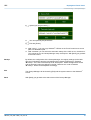
3.3 Connection to a PLC system.......................................................................... 26
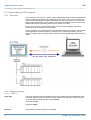
3.3.1 Overview...................................................................................................... 26
3.3.2 Integrated server......................................................................................... 26
3.3.3 Communication via ActiveSync................................................................... 31
3.4 Operating system Windows Embedded Compact 7....................................... 33
3.4.1 General........................................................................................................ 33
3.4.2 Structure...................................................................................................... 34
3.5 Access to the network resources.................................................................... 38
4 Industrial Security and Installation guidelines.................................................. 40
4.1 Industrial security in information technology................................................... 40
4.1.1 Protection of hardware and applications..................................................... 41
4.1.2 Protection of PC-based software................................................................. 42
4.2 Installation guidelines..................................................................................... 42
4.2.1 Basic rules for the EMC-equitable assembly of installations....................... 42
4.2.2 EMC-equitable assembly............................................................................. 46
4.2.3 EMC-equitable cabling................................................................................ 47
4.2.4 Special precautions providing high noise immunity..................................... 50
4.2.5 Checklist for the EMC-compliant installation of controllers.......................... 51
Appendix............................................................................................................... 52
A History of changes............................................................................................ 53
HMI Table of contents
HB160 | TP | 62I-JJK0 | en | 23-10 3

1 General
1.1 Copyright © YASKAWA Europe GmbH
This document contains proprietary information of Yaskawa and is not to be disclosed or
used except in accordance with applicable agreements.
This material is protected by copyright laws. It may not be reproduced, distributed, or
altered in any fashion by any entity (either internal or external to Yaskawa) except in
accordance with applicable agreements, contracts or licensing, without the express
written consent of Yaskawa and the business management owner of the material.
For permission to reproduce or distribute, please contact: YASKAWA Europe GmbH,
European Headquarters, Philipp-Reis-Str. 6, 65795 Hattersheim, Germany
Tel.: +49 6196 569 300
Fax.: +49 6196 569 398
Email: [email protected]
Internet: www.yaskawa.eu.com
Hereby, YASKAWA Europe GmbH declares that the products and systems are in compli-
ance with the essential requirements and other relevant provisions. Conformity is indi-
cated by the CE marking affixed to the product.
For more information regarding CE marking and Declaration of Conformity (DoC), please
contact your local representative of YASKAWA Europe GmbH.
SPEED7 is a registered trademark of YASKAWA Europe GmbH.
All Microsoft Windows, Office and Server products mentioned are registered trademarks
of Microsoft Inc., USA.
Portable Document Format (PDF) is a registered trademark of Adobe Systems, Inc.
All other trademarks, logos and service or product marks specified herein are owned by
their respective companies.
Every effort has been made to ensure that the information contained in this document
was complete and accurate at the time of publishing. We cannot guarantee that the infor-
mation is free of errors, and we reserve the right to change the information at any time.
There is no obligation to inform the customer about any changes. The customer is
requested to actively keep his documents up to date. The customer is always responsible
for the deployment of the products with the associated documentation, taking into
account the applicable directives and standards.
This documentation describes all hardware and software units and functions known
today. It is possible that units are described that do not exist at the customer. The exact
scope of delivery is described in the respective purchase contract.
Contact your local representative of YASKAWA Europe GmbH if you have errors or ques-
tions regarding the content of this document. You can reach YASKAWA Europe GmbH via
the following contact:
Email: [email protected]
All Rights Reserved
EC conformity declaration
Conformity Information
Trademarks
General terms of use
Document support
HMI
General
Copyright © YASKAWA Europe GmbH
HB160 | TP | 62I-JJK0 | en | 23-10 4

Contact your local representative of YASKAWA Europe GmbH if you encounter problems
or have questions regarding the product. If such a location is not available, you can reach
the Yaskawa customer service via the following contact:
YASKAWA Europe GmbH,
European Headquarters, Philipp-Reis-Str. 6, 65795 Hattersheim, Germany
Tel.: +49 6196 569 500 (hotline)
Email: [email protected]
1.2 About this manual
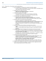
This manual describes the Touch Panel 62I-JJK0-EB.
nIt contains a description of the structure, project engineering and deployment.
nThe manual is written for users with basic knowledge of automation technology.
nThe manual consists of chapters. Each chapter describes a completed topic.
nThe following guides are available in the manual:
– An overall table of contents at the beginning of the manual.
– References with pages numbers.
Validity of the documentation
Product Order no. as of version:
TP 608C 62I-JJK0-EB HW: 01 FW: V1.0.2
Important passages in the text are highlighted by following icons and headings:
DANGER!
Immediate or likely danger. Personal injury is possible.
CAUTION!
Damages to property is likely if these warnings are not heeded.
Supplementary information and useful tips.
Technical support
Objective and contents
Icons Headings
HMI General
About this manual
HB160 | TP | 62I-JJK0 | en | 23-10 5

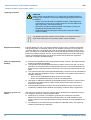
1.3 Safety information
The Touch Panels are constructed and produced for:
ncommunication and process control
ngeneral control and automation tasks
nindustrial applications
noperation within the environmental conditions specified in the technical data
ninstallation into a cubicle
DANGER!
This device is not certified for applications in
– in explosive environments (EX-zone)
The manual must be available to all personnel in the
nproject design department
ninstallation department
ncommissioning
noperation
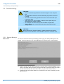
CAUTION!
The following conditions must be met before using or commis-
sioning the components described in this manual:
– Hardware modifications to the process control system should only be
carried out when the system has been disconnected from power!
– Installation and hardware modifications only by properly trained per-
sonnel.
– The national rules and regulations of the respective country must be
satisfied (installation, safety, EMC ...)
National rules and regulations apply to the disposal of the unit!
Applications conforming
with specifications
Documentation
Disposal
HMI
General
Safety information
HB160 | TP | 62I-JJK0 | en | 23-10 6

2 Hardware description
2.1 Safety information for users
The modules make use of highly integrated components in MOS-Technology. These com-
ponents are extremely sensitive to over-voltages that can occur during electrostatic dis-
charges. The following symbol is attached to modules that can be destroyed by electro-
static discharges.
The Symbol is located on the module, the module rack or on packing material and it indi-
cates the presence of electrostatic sensitive equipment. It is possible that electrostatic
sensitive equipment is destroyed by energies and voltages that are far less than the
human threshold of perception. These voltages can occur where persons do not dis-
charge themselves before handling electrostatic sensitive modules and they can damage
components thereby, causing the module to become inoperable or unusable. Modules
that have been damaged by electrostatic discharges can fail after a temperature change,
mechanical shock or changes in the electrical load. Only the consequent implementation
of protection devices and meticulous attention to the applicable rules and regulations for
handling the respective equipment can prevent failures of electrostatic sensitive modules.
Modules must be shipped in the original packing material.
When you are conducting measurements on electrostatic sensitive modules you should
take the following precautions:
nFloating instruments must be discharged before use.
nInstruments must be grounded.
Modifying electrostatic sensitive modules you should only use soldering irons with
grounded tips.
CAUTION!
Personnel and instruments should be grounded when working on electro-
static sensitive modules.
Handling of electrostatic
sensitive modules
Shipping of modules
Measurements and altera-
tions on electrostatic sen-
sitive modules
HMI Hardware description
Safety information for users
HB160 | TP | 62I-JJK0 | en | 23-10 7

2.2 Properties
The Touch Panel allows you to visualize and alter operating states and recent process
values of a connected PLC. The Touch Panelis a compact and modular embedded PC
based on WindowsÒ CE. Besides the extensive WindowsÒ CE functions the Touch Panel
offers varied communication possibilities. Here the Touch Panel can simply be configured,
controlled and remoted.
nWindowsÒ Embedded Compact 7
nMovicon 11 CE Standard (4096 I/O bytes)
nProcessor Freescale i.MX 6, ARM Cortex A9, 800 MHz
nWork memory 1GB
nUser memory 8GB
n6GB memory for user data
nCF-Card II and MMC/SD card slot
nRS232, RS422/485, MPI, PROFIBUS DP slave, Ethernet, USB-A and USB-B inter-
faces
nRobust aluminium die casting case
nDisplay SVGA 800 x 600 / 600 x 800 (16M colors)
nBattery backed clock
nResistive touch screen
nEasy mounting via integrated pivoted lever
nProtection class IP65 (frontal)
General
HMI
Hardware description
Properties
HB160 | TP | 62I-JJK0 | en | 23-10 8

Order data
Type Order number Description
TP 608C 62I-JJK0-EB 8.4" SVGA, TFT color, MPI/PROFIBUS DP/RS485, RS232,
RS422/485, 2xUSB-A, USB-B, 2xEthernet RJ45 (Switch)
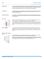
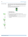
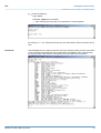
2.3 Structure
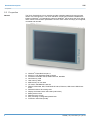
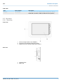
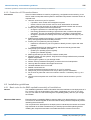
2.3.1 Overview
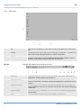
1 Slot for storage medium (CF, SD/MMC)
2 Connection for interfaces and power supply
3 Display with touch sensitive area (touch screen)
1 Compact Flash
2 MMC / SD
Front view
Side view
HMI Hardware description
Structure > Overview
HB160 | TP | 62I-JJK0 | en | 23-10 9

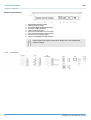
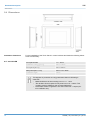
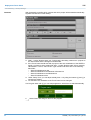
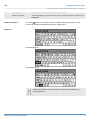
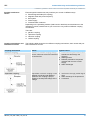
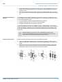
1 RS422/485 interface COM 2
2 RS232 interface COM 1
3 MPI/PROFIBUS DP/RS485 interface
4 2x "Host"-USB-A interface
5 "Slave"-USB-B interface
6 RJ45 jack for Ethernet communication
7 RJ45 jack for Ethernet communication
8 Slot for DC 24V voltage supply
9 Slot for CF/SD/MMC storage medium
Please make sure that the Touch Panel always has to be supplied with
external voltage!
2.3.2 Interfaces
Bottom view (Interfaces)
HMI
Hardware description
Structure > Interfaces
HB160 | TP | 62I-JJK0 | en | 23-10 10

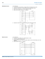
9 pin SubD jack
nLogical states represented by voltage differences between the 4 cores
nSerial bus connection in 4-wire technology using full duplex mode
nData communications up to a max. distance of 500m
nData communication rate up to 115.2kBaud
nSerial bus connection in 2-wire technology using half duplex mode
9 pin SubD plug
nInterface is compatible to the COM interface of a PC
nLogical signals as voltage levels
nPoint-to-point links with serial full-duplex transfer in two-wire technology up to 15m
distance
nData transfer rate up to 115.2kbit/s
RS422/485 interface
RS232 interface
HMI Hardware description
Structure > Interfaces
HB160 | TP | 62I-JJK0 | en | 23-10 11

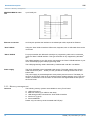
9 pin SubD jack
An RJ45 jack provides the interface to the twisted pair cable, required for Ethernet.
Using the "Host"-USB-A interface USB mouse, keyboard, stick or USB hard discs can be
connected.
For project transfer with Microsoft ActiveSync a programming cable can be connected
using the "Slave"-USB-B interface. This type of transfer is only supported by WindowsÒ
XP.
The USB-A interface of your PC can be connected to the "Slave"-USB-B interface of your
Touch Panel deploying the USB programming cable.
The USB programming cable is delivered by Yaskawa with order No. 670-0KB10.
The Touch Panelhas got an integrated power supply. The power supply has to be pro-
vided with DC 24V (20.4 ... 28.8V). For this you find an according DC 24V slot on the
bottom side.
The power supply is protected against inverse polarity and overcurrent. The battery for
the clock of the Touch Panel is an accumulator with a suitable charging circuit. This accu-
mulator is maintenance-free and does not need to be exchanged within the life span of
the Touch Panel.
2.3.3 Memory management
The following memory systems are available for every Touch Panel:
n1GB work memory
n8GB user memory (ca. 6GB for user data)
nUSB storage media connected via "Host"-USB-A interface
nSlot for CF (Type II)
nSlot for MMC/SD
Please only use memory cards formatted with FAT(32)!
MPI/PROFIBUS DP inter-
face
Ethernet connection
"Host"-USB-A
"Slave"-USB-B
Power supply
Overview
HMI
Hardware description
Structure > Memory management
HB160 | TP | 62I-JJK0 | en | 23-10 12

Every Touch Panell has a work memory with a size of 1GB. The work memory is not buf-
fered and is deleted after shut down. Please consider that also registry entries are stored
in the work memory that are set back to default settings after the next re-boot. You can
save them permanently by means of the KuK Tools (within consignment).
As internal permanent storage medium every Touch Panel has a flash disc with a size of
8GB (about 6GB user data). After the start of WindowsÒ CE this memory is listed as
Flashdiskunder My Device.
The connection of USB sticks and USB drives by use of the "Host"-USB-A interface is
supported by the Touch Panel. After connection the storage media is listed as Hard Disk
under My Device.
Here you can plug a CompactFlashÒ type II. The card may be plugged and removed
during runtime and is immediately listed as Storage Card at My Device.
Every CompactFlashÒ storage module has a pulling edge. Hold the CompactFlash in the
way that the pulling edge points to the left side. Push the storage module without much
power into the slot until the impact. To remove the card touch it at the pulling edge and
pull.
On this slot you can plug storage modules of the type SD or MMC. The card may be
plugged and removed during runtime and is immediately listed as SDMMC Card at My
Device Please take care to plug the according card as shown on the back of the Touch
Panel. .
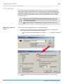
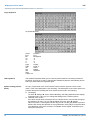
On the left side of the Touch Panel are the card slots for memory cards. The cards are
visibly covered by a security flap and are thus secured from slipping out.
Please take care to pull the security flap back before plugging or pulling a memory card
like shown in the illustration and put it back again afterwards. When plugging, the security
flap additionally snaps into position above the plugged memory card.
Work memory
User memory
USB storage media
Slot for CF
Slot for SD/MMC
Security flap for memory
cards
HMI Hardware description
Structure > Memory management
HB160 | TP | 62I-JJK0 | en | 23-10 13

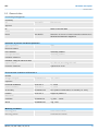
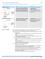
2.4 Dimensions
For the installation of the Touch Panel in control cabinets and desks the following dimen-
sions are necessary:
Front panel width 1.5 ... 6mm
Installation cutting (W x H) 250 x 175mm
Front panel (W x H) 264 x 189mm
Rear panel (W x H x D) 248 x 173 x 43mm
Installation depth 43mm
The degrees of protection are only guaranteed when the following is
observed:
–Material thickness at the mounting cut-out: 1.5 ... 6mm
–The deviation from the plane for the panel cut-out is
£
0.5mm. This
condition must be fulfilled for the mounted HMI device.
–Permissible surface roughness in the area of the seal:
£
120µm (fric-
tion coefficient 120)
Installation dimensions
8.4" - 62I-JJK0-EB
HMI
Hardware description
Dimensions
HB160 | TP | 62I-JJK0 | en | 23-10 14

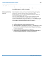
2.5 General data
Conformity and approval
Conformity
CE 2014/30/EU EMC directive
Approval
UL Refer to Technical data
others
RoHS 2011/65/EU Restriction of the use of certain hazardous substances in
electrical and electronic equipment
Protection of persons and device protection
Type of protection - IP20
Electrical isolation
to the field bus - electrically isolated
to the process level - electrically isolated
Insulation resistance -
Insulation voltage to reference earth
Inputs / outputs - AC / DC 50V, test voltage AC 500V
Protective measures - against short circuit
Environmental conditions to EN 61131-2
Climatic
Storage / transport EN 60068-2-14 -20…+60°C
Operation
Horizontal installation EN 61131-2 0…+50°C
Vertical installation EN 61131-2 0…+50°C
Air humidity EN 60068-2-30 RH1 (without condensation, rel. humidity 10…95%)
Pollution EN 61131-2 Degree of pollution 2
Mechanical
Oscillation EN 60068-2-6 1g, 9Hz ... 150Hz
Shock EN 60068-2-27 15g, 11ms
Mounting conditions
Mounting place - In the control cabinet
Mounting position - Horizontal and vertical
HMI Hardware description
General data
HB160 | TP | 62I-JJK0 | en | 23-10 15

EMC Standard Comment
Emitted interference EN 61000-6-4 Class A (Industrial area)
Noise immunity
zone B
EN 61000-6-2 Industrial area
EN 61000-4-2 ESD
8kV at air discharge (degree of severity 3),
4kV at contact discharge (degree of severity 2)
EN 61000-4-3 HF field immunity (casing)
80MHz … 1000MHz, 10V/m, 80% AM (1kHz)
1.4GHz ... 2.0GHz, 3V/m, 80% AM (1kHz)
2GHz ... 2.7GHz, 1V/m, 80% AM (1kHz)
EN 61000-4-6 HF conducted
150kHz … 80MHz, 10V, 80% AM (1kHz)
EN 61000-4-4 Burst, degree of severity 3
EN 61000-4-5 Surge, degree of severity 31
1) Due to the high-energetic single pulses with Surge an appropriate external protective circuit with lightning protection elements like conductors for lightning and overvoltage is
necessary.
2.6 Use in difficult operating conditions
Without additional protective measures, the products must not be used in
locations with difficult operating conditions; e.g. due to:
–dust generation
–chemically active substances (corrosive vapors or gases)
–strong electric or magnetic fields
HMI
Hardware description
Use in difficult operating conditions
HB160 | TP | 62I-JJK0 | en | 23-10 16

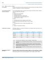
2.7 Technical data
2.7.1 62I-JJK0-EB
Order no. 62I-JJK0-EB
Type Touch Panel TP 608C
Display
Display size (diagonal) 8.4 "
Display size (width) 170.4 mm
Display size (height) 127.8 mm
Resolution 600 x 800 / 800 x 600
Aspect ratio 4:3
Type of display TFT color (16.7M colors)
MTBF Backlights (25°C) 50000 h
System properties
Processor ARM Cortex A9 800MHz
Operating system Windows Embedded Compact 7
User software Movicon 11 CE Standard
Work memory 1 GB
User memory 8 GB
Available memory (user data) 6 GB
SD/MMC Slot ü
CF Card Slot Typ II ü
CFast Slot -
Time
Real-time clock buffered ü
Clock buffered period (min.) 6 w
Type of buffering Vanadium Rechargeable Lithium Battery
Load time for 50% buffering period 10 h
Load time for 100% buffering period 48 h
Accuracy (max. deviation per day) 10 s
Operating controls
Touchscreen resistive
Touch function Single Touch
Keyboard external via USB
Mouse external via USB
Interfaces
MPI, PROFIBUS-DP RS485 isolated
MPI, PROFIBUS-DP connector Sub-D, 9-pin, female
HMI Hardware description
Technical data > 62I-JJK0-EB
HB160 | TP | 62I-JJK0 | en | 23-10 17

Order no. 62I-JJK0-EB
Serial, COM1 RS232
COM1 connector Sub-D, 9-pin, male
Serial, COM2 RS422/485 isolated
COM2 connector Sub-D, 9-pin, female
Number of USB-A interfaces 2
USB-A connector USB-A (host)
Number of USB-B interfaces 1
USB-B connector USB-B (device)
Number of ethernet interfaces 2
Ethernet Ethernet 10/100 MBit
Ethernet connector RJ45
Integrated ethernet switch ü
Video connectors -
Audio connections -
Technical data power supply
Power supply (rated value) DC 24 V
Power supply (permitted range) DC 20.4...28.8 V
Reverse polarity protection ü
Current consumption (no-load operation) 0.2 A
Current consumption (rated value) 0.3 A
Inrush current 1.84 A
I²t 0.05 A²s
Power loss 7.5 W
Status information, alarms, diagnostics
Status display green LED
Supply voltage display yes
Mechanical data
Housing / Protection class
Material die-cast aluminum
Mounting via integrated pivoted lever
Protection class IP front side IP 65
Protection class IP back side IP 20
Protection class NEMA front side -
Protection class NEMA back side -
Dimensions
Front panel 264 mm x 189 mm x 7.5 mm
HMI
Hardware description
Technical data > 62I-JJK0-EB
HB160 | TP | 62I-JJK0 | en | 23-10 18

Order no. 62I-JJK0-EB
Rear panel 248 mm x 173 mm x 43 mm
Installation cut-out
Width 250 mm
Height 175 mm
Minimum 1.5 mm
Maximum front panel thickness 6 mm
Net weight 2000 g
Weight including accessories 2700 g
Gross weight 2700 g
Environmental conditions
Operating temperature 0 °C to 50 °C
Storage temperature -25 °C to 70 °C
Certifications
UL certification in preparation
KC certification -
HMI Hardware description
Technical data > 62I-JJK0-EB
HB160 | TP | 62I-JJK0 | en | 23-10 19

3 Deployment Touch Panel
3.1 Installation
The Touch Panelis suitable for the installation in operating tables and control cabinet
fronts. The installation happens via the back. The Touch Panel is provided with a
patented integrated fixing technique that allows an easy connection with a simple screw-
driver.
Due to the fact that the Touch Panel has a plug connector for bus connection and voltage
supply, a fast and easy device change is possible.
For the installation into a operating tableau and control cabinet fronts, the Touch Panel
requires the following front plate cutting:
Touch Panel W x H in mm
62I-JJK0-EB 250 x 175
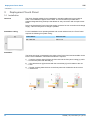
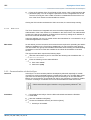
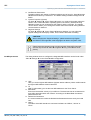
The fixing technique is integrated in the casing of the Touch Panel and accessible via the
back. For the installation, a small slit screwdriver is required
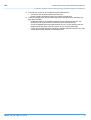
1. Push the operator panel [3] from the front side into the front panel cutting [1] until it
touches the panel with the seal [2].
2. Now bolt the lever [5] clockwise with the screwdriver [4] until it rotates to the out-
side.
3. Further screwing bolts the lever to the front panel until it holds this to the control
cabinet front.
Overview
Installation cutting
Installation
HMI
Deployment Touch Panel
Installation
HB160 | TP | 62I-JJK0 | en | 23-10 20
La pagina si sta caricando...
La pagina si sta caricando...
La pagina si sta caricando...
La pagina si sta caricando...
La pagina si sta caricando...
La pagina si sta caricando...
La pagina si sta caricando...
La pagina si sta caricando...
La pagina si sta caricando...
La pagina si sta caricando...
La pagina si sta caricando...
La pagina si sta caricando...
La pagina si sta caricando...
La pagina si sta caricando...
La pagina si sta caricando...
La pagina si sta caricando...
La pagina si sta caricando...
La pagina si sta caricando...
La pagina si sta caricando...
La pagina si sta caricando...
La pagina si sta caricando...
La pagina si sta caricando...
La pagina si sta caricando...
La pagina si sta caricando...
La pagina si sta caricando...
La pagina si sta caricando...
La pagina si sta caricando...
La pagina si sta caricando...
La pagina si sta caricando...
La pagina si sta caricando...
La pagina si sta caricando...
La pagina si sta caricando...
La pagina si sta caricando...
-
 1
1
-
 2
2
-
 3
3
-
 4
4
-
 5
5
-
 6
6
-
 7
7
-
 8
8
-
 9
9
-
 10
10
-
 11
11
-
 12
12
-
 13
13
-
 14
14
-
 15
15
-
 16
16
-
 17
17
-
 18
18
-
 19
19
-
 20
20
-
 21
21
-
 22
22
-
 23
23
-
 24
24
-
 25
25
-
 26
26
-
 27
27
-
 28
28
-
 29
29
-
 30
30
-
 31
31
-
 32
32
-
 33
33
-
 34
34
-
 35
35
-
 36
36
-
 37
37
-
 38
38
-
 39
39
-
 40
40
-
 41
41
-
 42
42
-
 43
43
-
 44
44
-
 45
45
-
 46
46
-
 47
47
-
 48
48
-
 49
49
-
 50
50
-
 51
51
-
 52
52
-
 53
53


VIPA professional Panel TP 608C Manuale del proprietario
- Tipo
- Manuale del proprietario
in altre lingue
Documenti correlati
-
VIPA professional Panel TP 612C Manuale del proprietario
-
-
-
-
-
-
-
-
-
Altri documenti
-
YASKAWA VIPA System SLIO Manuale utente
-
Mettler Toledo IND780 (11 MB) Guida d'installazione
-
ABB Relion 650 series ANSI Engineering Manual
-
ABB Relion REC615 Istruzioni per l'uso
-
ABB 615 Series ANSI 5.0 FP1, Protection Relay Istruzioni per l'uso
-
ProMinent DULCO flex Control-DFYa Operating Instructions Manual
-
Kollmorgen AKC-PCM-M Series Guida d'installazione
-
Woodward easYgen-1800 Manuale utente
-
WAGO ETHERNET Controller /XTR Manuale utente