
Chromalox
®
Chromalox
®
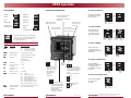
Front Panel Identification
•In Normal Display Mode,
pushbuttons adjust Setpoint.
•In Setup Mode, pushbuttons
increase/decrease MENU
values.
•For Ramp/soak Operation:
Pushbutton
•Reset Latching Alarm
•Hold for more than
3 seconds to enter or
exit Setup Mode
•Scrolls through
MENUs in
Setup Mode
}
Start
Hold
Press together
to Stop
LEDs indicate Alarm
or Event Output ON
LEDs indicate Control
Output #1 or #2 ON
•Process Variable Display in
Normal Display Mode
•Alphanumeric Cue Display in
Setup Mode
Active
Setpoint
Display
Chromalox
®
1382 Heil Quaker Boulevard • Lavergne, Tennessee 37086
Telephone: 615-793-3900 • FAX: 615-793-3563
2104 QuickInfo
Programmable Pushbutton
•PID1/PID2 Toggle Switch
•Auxiliary Setpoint Enable
•Remote Setpoint Enable
•Output Disable
•Ramp/Soak Operations
•Auto/Manual Selector
LEDs indicate
°F or °C selected for
Process Variable
LED indicates an
Auxiliary function
is active
Display
Control
Input
Ramp/Soak
Custom Input
Output Scaling
OO
OO
O
UT1UT1
UT1UT1
UT1
OO
OO
O
UT2UT2
UT2UT2
UT2
OO
OO
O
UT4UT4
UT4UT4
UT4
OO
OO
O
UT5UT5
UT5UT5
UT5
OO
OO
O
UT3UT3
UT3UT3
UT3
DiGDiG
DiGDiG
DiG
Output #1
Output #2
Output #3
Output #4
Output #5
Digital
Communications
DD
DD
D
iSPiSP
iSPiSP
iSP
CC
CC
C
TRLTRL
TRLTRL
TRL
II
II
I
NPTNPT
NPTNPT
NPT
RSPGRSPG
RSPGRSPG
RSPG
ScAScA
ScAScA
ScA
LL
LL
L
Ramp/Soak Page
MENU Description Available Settings
UNITUNIT
UNITUNIT
UNIT
Time Units SEc =seconds (1 to 9999)
MIN =minutes (0.1 to 999.9)
HR =hours (0.01 to 99.99)
STBSTB
STBSTB
STB
YY
YY
Y
Standby Setpoint Instrument Sensor Span
INT1INT1
INT1INT1
INT1
Interval 1 Time see Time Units Menu (above)
SP1SP1
SP1SP1
SP1
Setpoint 1 Instrument Sensor Span
•
• Intervals 2-16
• Time and Setpoint
CC
CC
C
ONTONT
ONTONT
ONT
Continuous OFF, ON
FF
FF
F
RORO
RORO
RO
Loop from the end 1 to 16
of interval
TOTO
TOTO
TO
To the beginning 1 to 16
of interval
NONO
NONO
NO
Number of times 0 to 9999
SBETSBET
SBETSBET
SBET
Standby Events OFF =All off
E3 =Event Output 3 On
E4 =Event Output 4 On
E43 =Event Outputs 4 & 3 On
E5 =Event Output 5 On
E53 =Event Outputs 5 & 3 On
E54 =Event Outputs 5 & 4 On
E543 =Event Outputs 5, 4, 3 On
ILEILE
ILEILE
ILE
Interval 1-16 Events same as above for Stand by Events
GG
GG
G
SDBSDB
SDBSDB
SDB
Guaranteed Soak OFF, 1°F to sensor range
Differential
This setup PAGE appears only if Ramp/Soak
control is turned on. The Ramp/Soak Enable
parameter is the next to the last menu on
CTRL PAGE, Menu
RSEN
.
RSPGRSPG
RSPGRSPG
RSPG
PP
PP
P
AA
AA
A
GEGE
GEGE
GE
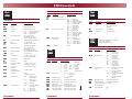
Setup PAGES
To enter Setup Mode:
Hold down the RESET
pushbutton for longer
than 3 seconds.
RESET AUX
SPSP
SPSP
SP
250250
250250
250
➮
RESET AUX
250250
250250
250
250250
250250
250
☛
Setup Mode
entered.
Hold for at
least
3 seconds.
➮
RESET AUX
SPSP
SPSP
SP
250250
250250
250
To select a PAGE:
Press and hold the
Reset pushbutton,
while pressing the
▲ or ▼ Pushbutton.
☛
Hold Press ▲ or ▼
☛
RESET AUX
Hold Press ▲ or ▼
CC
CC
C
TRLTRL
TRLTRL
TRL
PP
PP
P
AA
AA
A
GEGE
GEGE
GE
☛
After reaching the
correct PAGE, press
RESET to move through
the MENUs.
➮
RESET AUX
CYcCYc
CYcCYc
CYc
LL
LL
L
250250
250250
250
☛
To select a MENU:
RESET AUX
OL1OL1
OL1OL1
OL1
100.0100.0
100.0100.0
100.0
☛
After the MENU is
selected and displayed,
use the ▲ and ▼
pushbuttons to change
the value.
➮
RESET AUX
CYcCYc
CYcCYc
CYc
LL
LL
L
1.01.0
1.01.0
1.0
To change a MENU value:
RESET AUX
1.51.5
1.51.5
1.5
CYcCYc
CYcCYc
CYc
LL
LL
L
☛
☛
Press and hold RESET
for more than 3
seconds.
RESET AUX
SS
SS
S
TBTB
TBTB
TB
YY
YY
Y
250250
250250
250
☛
To return to Operating Mode:
Hold for at
least
3 seconds.
P/N 0037- 75241
RESET
AUX
☛

RTD = 100Ω RTD
(α = .00385)
4-20 = 4-20mA
0-5 = 0-5 Vdc
1-5 = 1 t-5 Vdc
RTDT = 100Ω RTD
(0.1˚
Chromalox
®
Chromalox
®
Chromalox
®
2104 QuickInfo
Outputs #1 and #2
MENU Description Available Settings
CC
CC
C
YY
YY
Y
C1C1
C1C1
C1
Output #1 Cycle 0.0 to 60.0 seconds
Time 0.0 = Voltage/Current
algorithm
OLOL
OLOL
OL
11
11
1
Output #1 Limit 0.0 to 100.0%
HH
HH
H
OFFOFF
OFFOFF
OFF
Heat Offset 0°F to PB1 setting
Outputs #3, #4 and #5
MENU Description Available Settings
TT
TT
T
YY
YY
Y
P3P3
P3P3
P3
Output #3 Type OFF = Disabled
ALR = Alarm Output
ENT = Event Output
AA
AA
A
LR3LR3
LR3LR3
LR3
Alarm #3 Type NONE = Disabled (off)
Hi = High Alarm
Lo = Low Alarm
HiLo = High-Low Alarm
PDE = + Dev Alarm
-DE = - Dev Alarm
DE = +/- Dev Alarm
LooP = Control Loop
Protection Alarm
RR
RR
R
LL
LL
L
YY
YY
Y
33
33
3
Alarm #3 Relay NDE = Normally de-energized
Action non-latching
NE = Normally energized
non-latching
NDEL = Normally de-energized
latching
NEL = Normally energized
latching
ALAL
ALAL
AL
O3O3
O3O3
O3
Alarm #3 Low SP Instrument Sensor Span
AHAH
AHAH
AH
I3I3
I3I3
I3
Alarm #3 High SP Instrument Sensor Span
DB3DB3
DB3DB3
DB3
Output #3 Dead Band 0 to 100°F
(Alarm Hysteresis)
INH3INH3
INH3INH3
INH3
Alarm #3 Inhibit OFF
ON
OO
OO
O
UT3UT3
UT3UT3
UT3
PP
PP
P
AA
AA
A
GEGE
GEGE
GE
These setup PAGES appear only if the
controller is equipped
with Outputs #3, #4 and #5.
OO
OO
O
UT1UT1
UT1UT1
UT1
PP
PP
P
AA
AA
A
GEGE
GEGE
GE
Control Page (continued)
MENU Description Available Settings
RR
RR
R
SPSP
SPSP
SP
Remote Setpoint Enable OFF, On
EE
EE
E
NTINTI
NTINTI
NTI Event/Digital Input Function NONE = Disabled
PID2 = PID2 enable
AUSP = Auxiliary SP enable
RSP = Remote SP enable
OUTD = Output disable
RS = Ramp/Soak
AUTO = Auto/Manual
ALR = Alarm Reset
AA
AA
A
UU
UU
U
Auxiliary Key Function NONE = Disabled
PID2 = PID2 enable
AUSP = Auxiliary SP enable
RSP = Remote SP enable
OUTD = Output disable
AUTO = Auto/Manual
AA
AA
A
OUTOUT
OUTOUT
OUT
Analog Output NONE = Disabled
Assignment PROC = Process Variable
ASP = Active Setpoint
OUT1 = Control Output 1
OUT2 = Control Output 2
RR
RR
R
SESE
SESE
SE
NN
NN
N
Ramp/Soak OFF, ON
Input Page
MENU Description Available Settings
SESE
SESE
SE
NN
NN
N
SS
SS
S
Sensor Type J = J T/C
K = K T/C
T = T T/C
E = E T/C
R = R T/C
S = S T/C
B = B T/C
UNITUNIT
UNITUNIT
UNIT
Display Units NONE = no units
°F = Fahrenheit
°C = Celsius
CC
CC
C
OO
OO
O
FFFF
FFFF
FF
Calibration Offset 0 to ±100°F
SPLLSPLL
SPLLSPLL
SPLL
Setpoint Low Limit Instrument Sensor Span
SPULSPUL
SPULSPUL
SPUL
Setpoint Upper Limit Instrument Sensor Span
FF
FF
F
II
II
I
LL
LL
L
TT
TT
T
Digital Filter 0 to 60 Seconds D
HPRCHPRC
HPRCHPRC
HPRC
High Process Input Instrument Sensor Span
LL
LL
L
PRCPRC
PRCPRC
PRC
Low Process Input Instrument Sensor Span
HIHI
HIHI
HI
AA
AA
A
High Ambient Temp. Instrument Sensor Span
LL
LL
L
OO
OO
O
AA
AA
A
Low Ambient Temp. Instrument Sensor Span
II
II
I
NPTNPT
NPTNPT
NPT
PP
PP
P
AA
AA
A
GEGE
GEGE
GE
Control Page
MENU Description Available Settings
LL
LL
L
OCOC
OCOC
OC
HH
HH
H
Security Lock 0 to 9999
SPSP
SPSP
SP
Setpoint Instrument sensor span
AA
AA
A
UU
UU
U
SPSP
SPSP
SP
Auxiliary SP Instrument sensor span
TUNTUN
TUNTUN
TUN
EE
EE
E
Self Tune OFF = Self-tuning disabled
PRUP = Power-up tuning
BEGN = Begin tuning
PP
PP
P
BB
BB
B
11
11
1
Proportional Band 1 0°F to sensor range
0°F displays as
OnOF
to
indicate ON/OFF control
AA
AA
A
RR
RR
R
11
11
1
Automatic Reset 1 0.00 to 99.99 repeats/minute
RR
RR
R
AA
AA
A
TT
TT
T
11
11
1
Rate 1 0 to 500 seconds
DB1DB1
DB1DB1
DB1
Dead Band 1 1 to 100°F, 0.01 to 6.25%
span for analog inputs
PP
PP
P
BB
BB
B
22
22
2
Proportional Band 2 0°F to sensor range
0°F displays as
OnOF
to
indicate ON/OFF control
AA
AA
A
RR
RR
R
22
22
2
Automatic Reset 2 0.00 to 99.99 repeats/minute
RR
RR
R
AA
AA
A
TT
TT
T
22
22
2
Rate 2 0 to 500 seconds
DBDB
DBDB
DB
22
22
2
Dead Band 2 1 to 100°F, 0.01 to 6.25%
span for analog inputs
OFSOFS
OFSOFS
OFS
TT
TT
T
Manual Reset -99.9 to 99.9
FLFL
FLFL
FL
Fuzzy Logic OFF, ON
OO
OO
O
RNGRNG
RNGRNG
RNG
Open Sensor Output -100.0 to -0.1 for cooling
Command 0.1 to 100.0 for heating
LL
LL
L
OOPOOP
OOPOOP
OOP
Control Loop OFF, 0.1 to 999.9 minutes
Protection
AA
AA
A
UTOUTO
UTOUTO
UTO
Auto/Manual 0 to 100 seconds
Disintegration time
RRRR
RRRR
RR
AA
AA
A
TT
TT
T
Ramp Rate OFF or
1 to 9999 degrees/hour
CC
CC
C
ONTONT
ONTONT
ONT
Controller Type HEAT = Reverse Acting
Single Output
COOL = Direct Acting
Single Output
HTCL = Heat/Cool
CC
CC
C
OOOO
OOOO
OO
LL
LL
L
Cooling Medium PID2 = Uses PID2 settings
for cooling
AIR = Air Cooling
OIL = Oil Cooling
H2O = Water Cooling
CC
CC
C
TRLTRL
TRLTRL
TRL
PP
PP
P
AA
AA
A
GEGE
GEGE
GE
▼
Resolution)
-
 1
1
-
 2
2


Altri documenti
-
Omega CN3240 Series Manuale del proprietario
-
Eurotherm 2404, 2408 Manuale del proprietario
-
-
-
-
-
-
gefran 600 Manuale utente
-
-
CARLO GAVAZZI SHA4XLS2TEMDIS Manuale utente