
LFS - ServoLFS - Servo
LFS - ServoLFS - Servo
LFS - Servo
170.IU0.LFS.SD0 01/11
UU
UU
U
USER MANUAL USER MANUAL
USER MANUAL USER MANUAL
USER MANUAL
UU
UU
U
ISTRUZIONI D'USO ISTRUZIONI D'USO
ISTRUZIONI D'USO ISTRUZIONI D'USO
ISTRUZIONI D'USO
LFSSV-0-D0.pmd 11/01/2011, 13.211

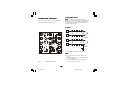
INDEXINDEX
INDEXINDEX
INDEX
MOUNTING REQUIREMENTS........................... 1
OUTLINE AND CUT OUT DIMENSIONS ........... 2
CONNECTION DIAGRAMS ................................ 3
PRELIMINARY HARDWARE SETTINGS........... 9
CONFIGURATION PROCEDURE .................... 10
OPERATIVE MODE.......................................... 19
Display function.......................................... 19
Indicators ................................................... 19
Pushbutton function during operating mode 20
Feedback potentiometer calibration ........... 20
Enable/disable the control output ............... 21
Manual function.......................................... 21
Direct access to the set point ..................... 22
Operative set point selection ...................... 22
Lamp test ................................................... 22
Serial link ................................................... 23
SMART function......................................... 23
OPERATIVE PARAMETERS............................ 24
ERROR MESSAGES........................................ 27
GENERAL INFORMATION............................... 30
MAINTENANCE ................................................... 34
ELECTRICAL AND SAFETY SYMBOLS ................ 35
DEFAULT PARAMETERS ...................................A.1
GBGB
GBGB
GB
INDICEINDICE
INDICEINDICE
INDICE
MONTAGGIO ....................................................... 1
DIMENSIONI E FORATURA ................................... 2
COLLEGAMENTI ELETTRICI.................................. 3
IMPOSTAZIONI HARDWARE PRELIMINARI ........... 9
PROCEDURE DI CONFIGURAZIONE ................... 10
MODO OPERATIVO ............................................ 20
Funzionalità del visualizzatore ..................... 20
Indicatori .................................................... 20
Operatività dei tasti durante
il modo operativo ........................................ 21
Calibrazione del potenziometro
di controreazione ........................................ 21
Abilitazione/disabilitazione
dell'uscita regolante ................................... 22
Funzionamento in modo MANUALE ............. 22
Modifica diretta del set point ...................... 23
Selezione del set point operativo ................ 23
Lamp test ................................................... 23
Interfaccia seriale ....................................... 24
Funzione SMART ........................................ 24
PARAMETRI OPERATIVI ..................................... 25
MESSAGGI DI ERRORE ..................................... 28
CARATTERISTICHE TECNICHE ........................... 31
MANUTENZIONE ................................................. 35
LEGENDA SIMBOLI ELETTRICI E DI SICUREZZA . 36
DEFAULT PARAMETERS ...................................A.1
II
II
I
(Applicable in the countries of the
European Union)
The label on the instruction
manual and on the carton box indicates that
the product, is compliant with the requests of
the European Directive nr. 2002/92/CE regarding
the restriction of hazardous substances in
electric and electronic apparatus.
(Applicabile nei paesi dell’Unione
Europea)
Il marchio riportato sulla
documentazione e sulla scatola da imballo , indica
che il prodotto è conforme alle richieste della
Direttiva Europea nr. 2002/92/CE relativa alla
riduzione dell’uso di sostanze pericolose nelle
apparecchiature elettriche ed elettroniche.
LFSSV-0-D0.pmd 11/01/2011, 13.212

LFSSV-0-D0.pmd 11/01/2011, 13.213

1
GBGB
GBGB
GB
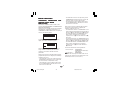
MOUNTING REQUIREMENTSMOUNTING REQUIREMENTS
MOUNTING REQUIREMENTSMOUNTING REQUIREMENTS
MOUNTING REQUIREMENTS
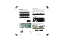
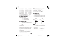
Select a mounting location where there is
minimum vibration and the ambient temperature
range between 0 and 50 °C.
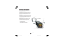
The instrument can be mounted on a panel up to
15 mm thick with a square cutout of 45 x 45 mm.
For outline and cutout dimensions refer to Fig. 2.
The surface texture of the panel must be better
than 6,3 μm.
The instrument is shipped with rubber panel gasket
(50 to 60 Sh).
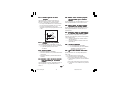
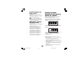
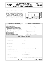
To assure the IP65 and NEMA 4 protection, insert
the panel gasket between the instrument and the
panel as shown in fig. 1.
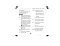
While holding the instrument against the panel
proceed as follows:
1) insert the gasket in the instrument case;
2) insert the instrument in the panel cutout;
3) pushing the instrument against the panel, insert
the mounting bracket;
4) with a screwdriver, turn the screws with a
torque between 0.3 and 0.4 Nm.
Screw
Fig. 1
bracket
Panel
Gasket
LFSSV-1-D0.pmd 11/01/2011, 13.431

2
GBGB
GBGB
GB
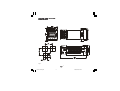
OUTLINE AND CUT OUTOUTLINE AND CUT OUT
OUTLINE AND CUT OUTOUTLINE AND CUT OUT
OUTLINE AND CUT OUT
DIMENSIONSDIMENSIONS
DIMENSIONSDIMENSIONS
DIMENSIONS
Fig. 2
LFSSV-1-D0.pmd 11/01/2011, 13.432

3
GBGB
GBGB
GB
CONNECTION DIAGRAMSCONNECTION DIAGRAMS
CONNECTION DIAGRAMSCONNECTION DIAGRAMS
CONNECTION DIAGRAMS
Connections are to be made with the instrument
housing installed in its proper location.
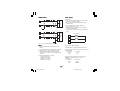
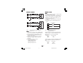
Fig. 3 REAR TERMINAL BLOCK
A) MEASURING INPUTA) MEASURING INPUT
A) MEASURING INPUTA) MEASURING INPUT
A) MEASURING INPUT
NOTENOTE
NOTENOTE
NOTE: Any external components (like zener
barriers etc.) connected between sensor and input
terminals may cause errors in measurement due to
excessive and/or not balanced line resistance or
possible leakage currents.
TC INPUTTC INPUT
TC INPUTTC INPUT
TC INPUT
Fig. 4 THERMOCOUPLE INPUT WIRING
NOTENOTE
NOTENOTE
NOTE:
1) Don’t run input wires together with power
cables.
2) For TC wiring use proper compensating cable
preferable shielded.
3) when a shielded cable is used, it should be
connected at one point only.
Shield
Shield
10
9
+
_
10
9
+
_
LFSSV-1-D0.pmd 11/01/2011, 13.433

4
GBGB
GBGB
GB
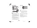
LINEAR INPUTLINEAR INPUT
LINEAR INPUTLINEAR INPUT
LINEAR INPUT
Fig. 5 mA, mV AND V INPUTS WIRING
NOTENOTE
NOTENOTE
NOTE:
1) Don’t run input wires together with power
cables.
2) Pay attention to the line resistance; a high line
resistance may cause measurement errors.
3) When shielded cable is used, it should be
grounded at one side only to avoid ground loop
currents.
4) The input impedance is equal to:
< 5 Ω for 20 mA input
> 1 MΩ for 60 mV input
> 400 kΩ for 5 V input
> 400 kΩ for 10 V input
LOGIC INPUTLOGIC INPUT
LOGIC INPUTLOGIC INPUT
LOGIC INPUT
Safety note:
1) The "serial comunication" and the "logic input"
options are mutually exclusive.
2) Do not run logic input wiring together with
power cables.
3) Use an external dry contact capable of
switching 0.5 mA, 5 V DC.
4) The instrument needs 100 ms to recognize a
contact status variation.
5) The logic inputs are isolated by the measuring
input
Fig. 7 - LOGIC INPUT WIRING
This instrument is provided with 2 logic inputs.
The logic input 1 allows to select the operative set
point as follows
logic input 1 op. set point
open SP
close SP2
The logic input 2 allows to select the AUTO /
MANUAL operative mode (see also P24
parameter):
logic input 2 operat. mode
open AUTO
close MANUAL
Shield
_
+
mA,
mV
or
V
9
+
_
G
mA
mV
or
V
10
9
10
11
Log. input 1
12
13
Log. input 2
LFSSV-1-D0.pmd 11/01/2011, 13.434

5
GBGB
GBGB
GB
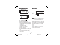
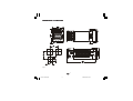
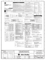
VALVE MOTOR DRIVE OUTPUT.VALVE MOTOR DRIVE OUTPUT.
VALVE MOTOR DRIVE OUTPUT.VALVE MOTOR DRIVE OUTPUT.
VALVE MOTOR DRIVE OUTPUT.
Fig. 8 - SERVOMOTOR WIRING
The two relay outputs are interlocked.
NOTENOTE
NOTENOTE
NOTE:
1) Before connecting the instrument to the power line,
make sure that line voltage and the load current are
in accordance with the contact rating (3A/250V AC
on resistive load).
2) To avoid electric shock, connect power line at the
end of the wiring procedure.
3) For servomotor connections use No 16 AWG or
larger wires rated for at last 75 °C.
4) Use copper conductors only.
5) Don’t run input wires together with power cables.
6) For feedback potentiometer, use shielded cable
with the shield connected to the earth at one point
only.
7) The relay outputs are protected by varistor
against inductive load with inductive compo-
nent up to 0.5 A.
1
2
3
Servo-
motor
Power
line
V (Open the valve)
W (Close the valve)
RELAY OUTPUTSRELAY OUTPUTS
RELAY OUTPUTSRELAY OUTPUTS
RELAY OUTPUTS
Fig. 9 RELAY OUTPUTS WIRING
NOTENOTE
NOTENOTE
NOTE: OUT 1 can be used either as servomotor
output or as time proportional relay output;
by the P5 parameter (see pag.11) it is
possible to set the desired output.
All relay outputs are protected by varistor against
inductive load with inductive component up to 0.5 A.
The contact rating of the OUT 3 and 4 is 2A/250V AC
resistive load.
The number of operations is 1 x 10
5
at specified
rating.
Alarm 2 and alarm 3 are in OR condition on the
out 4.
The following recommendations avoid serious
problems which may occur, when using relay
output for driving inductive loads.
8
6
7
C - OUT 3/4
NO - OUT 4
NO - OUT 3
OUT 4
OUT 3
14
15
Feedback
potentiometer
Shield
LFSSV-1-D0.pmd 11/01/2011, 13.435

6
GBGB
GBGB
GB
INDUCTIVE LOADSINDUCTIVE LOADS
INDUCTIVE LOADSINDUCTIVE LOADS
INDUCTIVE LOADS
High voltage transients may occur when switching
inductive loads.
Through the internal contacts these transients may
introduce disturbances which can affect the
performance of the instrument.
The internal protection (varistor) assures a correct
protection up to 0.5 A of inductive component.
The same problem may occur when a switch is
used in series with the internal contacts as shown
in Fig. 10.
Fig. 10 EXTERNAL SWITCH IN SERIES WITH THE
INTERNAL CONTACT
In this case it is recommended to install an
additional RC network across the external contact
as shown in Fig. 10
The value of capacitor (C) and resistor (R) are
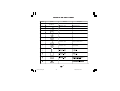
shown in the following table.
Anyway the cable involved in relay output wiring
must be as far away as possible from input or
communication cables.
SERIAL INTERFACESERIAL INTERFACE
SERIAL INTERFACESERIAL INTERFACE
SERIAL INTERFACE
RS-485 interface allows to connect up to 30
devices with one remote master unit.
Fig. 11 - RS-485 WIRING
The cable length must not exceed 1.5 km at 9600
BAUD.
The "serial comunication" and the "logic input"
options are mutually exclusive.
NOTENOTE
NOTENOTE
NOTE:The following report describes the signal
sense of the voltage appearing across the
interconnection cable as defined by EIA for
RS-485.
a) The ” A ” terminal of the generator shall be
negative with respect to the ” B ” terminal for
a binary 1 (MARK or OFF) state.
b) The ” A ” terminal of the generator shall be
positive with respect to the ” B ” terminal for
a binary 0 (SPACE or ON)
12
13
COMMON
11
B'/B
B/B'
A/A'
A'/A
M
A
S
T
E
R
I
N
S
T
R
U
M
E
N
T
LOAD
(mA)
<40 mA
<150 mA
<0.5 A
C
(μF)
0.047
0.1
0.33
R
(Ω)
100
22
47
P.
(W)
1/2
2
2
OPERATING
VOLTAGE
260 V AC
260 V AC
260 V AC
LFSSV-1-D0.pmd 11/01/2011, 13.436

7
GBGB
GBGB
GB
POWER LINE WIRINGPOWER LINE WIRING
POWER LINE WIRINGPOWER LINE WIRING
POWER LINE WIRING
Fig. 12 POWER LINE WIRING
NOTENOTE
NOTENOTE
NOTE:
1) Before connecting the instrument to the power
line, make sure that line voltage corresponds to the
descrtiption on the identification label.
2) To avoid electric shock, connect power line at the
end of the wiring procedure.
3) For supply connections use No 16 AWG or larger
wires rated for at last 75 °C.
4) Use copper conductors only.
5) Don't run input wires together with power cables.
6) For 24 V DC the polarity is a do not care condition.
7) The power supply input is fuse protected by a sub
miniature fuse rated T, 1A, 250 V.
When fuse is damaged, it is advisable to verify the
power supply circuit, so that it is necessary to send
back the instrument to your supplier.
8) The safety requirements for Permanently Con-
nected Equipment say:
- a switch or circuit-breaker shall be included in the
building installation;
- It shall be in close proximity to the equipment and
within easy reach of the operator;
- it shall be marked as the disconnecting device for
the equipment.
NOTENOTE
NOTENOTE
NOTE: a single switch or circuit-breaker can drive
more than one instrument.
9) When a neutral line is present, connect it to
terminal 5.
R (S,T)
R (S,T)
N
N
POWER LINE 100 V to 240 V A.C (50/
60Hz)
4
5
LFSSV-1-D0.pmd 11/01/2011, 13.437

8
GB
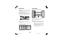
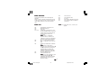
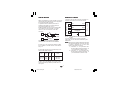
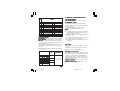
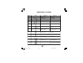
PRELIMINARY HARDWARE
SETTINGS
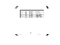
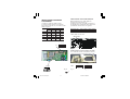
1) Remove the instrument from its case.
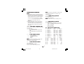
2) It is necessary to set J1 according to the desired
input type as shown in the following figure.
INPUT J1
TYPE 1-2 3-4 5-6 7-8
TC close open open open
60 mV close open open open
5 V open close open open
10 V open open close open
20 mA open open open close
OPEN INPUT CIRCUIT
This instrument is able to identify the open circuit
for TC input.
For TC input, it is possible to select overrange
indication (standard) or underrange indication set-
ting the CH1 and SH1 according to the following
table:
Overrange (STD) CH1 = close SH1 = open
Underrange CH1 = open SH1 = close
Both pads are located on the soldering side of the
CPU card
Logic input - serial interface selection
When both options are fitted, select the desired
function by setting J105 as follows:
Fig.15
Fig. 13
Fig. 14
Fig. 13
SH1 CH1
SW1
1 3 5 7
2 4 6 8
J1
J105
Logic inputs
1 3 5 7
2 4 6 8
1 3 5 7
2 4 6 8
RS-485
LFS-servo-1-02.p65 10/18/01, 6:57 PM8
7 5 3 1
7 5 3 1
8 6 4 2
8 6 4 2

9
GBGB
GBGB
GB
INSTRUMENT CONFIGURATIONINSTRUMENT CONFIGURATION
INSTRUMENT CONFIGURATIONINSTRUMENT CONFIGURATION
INSTRUMENT CONFIGURATION
1) Switch on the instrument.
The upper display shows the measured value while
the lower display shows the programmed set point
value (we define the above condition as “normal
display mode”).
2) Push "FUNC" pushbutton and, maintaining the
pressure, push the "MAN" pushbutton for more
than 4 seconds.
The lower display will show
ConF while the
upper display will show
C.mOn.
NOTENOTE
NOTENOTE
NOTE: two different configuration mode are
possible:
A)
Monitor modeMonitor mode
Monitor modeMonitor mode
Monitor mode: in this mode it is possible
to monitor but not to modify the configuration
parameter. During the monitor mode the
instrument continue to perform the standard
control.
B)
Modify modeModify mode
Modify modeModify mode
Modify mode: in this mode it is possible to
verify and to modify all configuration
parameter.
3) By and pushbuttons select the
C.mOd
indication (modify mode).
4) Push the "FUNC" pushbutton.
NOTESNOTES
NOTESNOTES
NOTES:
1) When modify mode is started, the instrument
stops the control action and:
- sets control outputs to OFF;
- sets alarms in no alarm condition;
- disables the serial link.
2) If the configuration parameters are protected by
security code the display will show:
By and keys enter a value equal to the
configuration security code (see P51 parameter)
or the master key code (see appendix A).
Note:Note:
Note:Note:
Note: the master key code allows to enter in modify
configuration parameters mode either if the
configuration security code is lost or if the configu-
ration parameters are always protected (P51 = 1).
When it is desired to exit from configuration modify
mode proceed as follows:
a) Push "FUNC" or "MAN" push-button more times
until the
C.End parameter is displayed.
b) Pushing ”” or “” push-button select the
yes
indication.
c) Push “FUNC” push-button. The instrument ends
the configuration modify mode, preforms an
automatic reset and restarts in the run time
mode.
Pushbutton function during configurationPushbutton function during configuration
Pushbutton function during configurationPushbutton function during configuration
Pushbutton function during configuration
modemode
modemode
mode
FUNC = This will memorize the new value of the
selected parameter and go to the next
parameter (increasing order).
MAN = This will scroll back the parameters
without memorization of the new value.
= This will increase the value of the
selected parameter
= This will decrease the value of the
selected parameter.
LFSSV-1-D0.pmd 11/01/2011, 13.449

10
GBGB
GBGB
GB
CONFIGURATION PARAMETERSCONFIGURATION PARAMETERS
CONFIGURATION PARAMETERSCONFIGURATION PARAMETERS
CONFIGURATION PARAMETERS
Notes:Notes:
Notes:Notes:
Notes:
1) In the following pages we will describe all the
parameters of the instrument but the instrument
will show only the parameters related with the
specific hardware and in accordance with the
specific instrument configuration (i.e. setting
Ser1 = OFF (not used), all the parameters
related with serial interface will not be
displayed).
2) During configuration mode, the lower display
shows the mnemonic code of the selected
parameter while the upper display shows the
value or the status assigned to the selected
parameter.
Ld. dFLd. dF
Ld. dFLd. dF
Ld. dF
- Load default configuration data - Load default configuration data
- Load default configuration data - Load default configuration data
- Load default configuration data
This parameter is skipped in monitor configuration
parameter mode.
OFF = No default data loading
tb.1 = Load default data from European table
(TB1)
tb.2 = Load default data from American table
(TB2)
SEr1SEr1
SEr1SEr1
SEr1
= Serial interface protocol = Serial interface protocol
= Serial interface protocol = Serial interface protocol
= Serial interface protocol
OFF = No serial interface
ero = Polling/selecting ERO
nbUs = Modbus
jbUs = Jbus
NOTENOTE
NOTENOTE
NOTE: the "serial comunication" and the "logic
input" options are mutually exclusive and
selectable by a jumper setting.
ser2ser2
ser2ser2
ser2
= Serial link device address = Serial link device address
= Serial link device address = Serial link device address
= Serial link device address
Not available when SEr1 = OFF
From 1 to 95 for ERO protocol
From 1 to 255 for all the other protocols
NOTENOTE
NOTENOTE
NOTE: the electrical characteristic of the RS 485
serial interface will allow the connection of 31
devices maximum.
ser3ser3
ser3ser3
ser3
= Baude rate for serial link = Baude rate for serial link
= Baude rate for serial link = Baude rate for serial link
= Baude rate for serial link
Not available when SEr1 = OFF
From 600 to 19200 baud.
NOTE
NOTE
NOTENOTE
NOTE: 19200 baud is shown on display as 19.2.
ser4ser4
ser4ser4
ser4
= Byte format for serial link = Byte format for serial link
= Byte format for serial link = Byte format for serial link
= Byte format for serial link
Not available when SEr1 = OFF
7e = 7 bits + even parity (For ERO protocol only)
7O = 7 bits + odd parity (For ERO protocol only)
8E = 8 bits + even parity
8O = 8 bits + odd parity
8 = 8 bits without parity
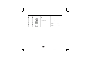
P1 - Input type and standard rangeP1 - Input type and standard range
P1 - Input type and standard rangeP1 - Input type and standard range
P1 - Input type and standard range
0 = TC type L range 0 / +400.0 °C
1 = TC type L range 0 / +900 °C
2 = TC type J range -100.0 / +400.0 °C
3 = TC type J range -100 / +1000 °C
4 = TC type K range -100.0 / +400.0 °C
5 = TC type K range -100 / +1370 °C
6 = TC type T range -199.9 / +400.0 °C
7 = TC type N range -100 / +1400 °C
8 = TC type R range 0 / +1760 °C
9 = TC type S range 0 / +1760 °C
10 = TC type B range 0 / +1820 °C
13 = mV Linear range 0 / 60 mV
14 = mV Linear range 12 / 60 mV
15 = mA Linear range 0 / 20 mA
16 = mA Linear range 4 / 20 mA
17 = V Linear range 0 / 5 V
18 = V Linear range 1 / 5 V
19 = V Linear range 0 / 10 V
20 = V Linear range 2 / 10 V
LFSSV-1-D0.pmd 11/01/2011, 13.4410

11
GBGB
GBGB
GB
21 = TC type L range 0 / +1650 °F
22 = TC type J range -150 / +1830 °F
23 = TC type K range -150 / +2500 °F
24 = TC type T range -330 / +750 °F
25 = TC type N range -150 / +2550 °F
26 = TC type R range 0 / +3200 °F
27 = TC type S range 0 / +3200 °F
28 = TC type B range 0 / + 3310 °F
NOTENOTE
NOTENOTE
NOTE: selecting P1 = 0, 2, 4, 6, 10 or 28, the
instrument set automatically P43 = filt. For all
the remaining ranges it will set P43 = nOfl.
P2 = Decimal point positionP2 = Decimal point position
P2 = Decimal point positionP2 = Decimal point position
P2 = Decimal point position
This parameter is available only when a linear input
is selected (P1 = 13 to 20).
----. = No decimal figure.
---.- = One decimal figure.
--.-- = Two decimal figures.
-.--- = Three decimal figures.
P3 = Initial scale valueP3 = Initial scale value
P3 = Initial scale valueP3 = Initial scale value
P3 = Initial scale value
For linear inputs, it is programmable from -1999 to 4000
and P3 value may be greater than P4 value
in order to obtain a reverse read-out.
For TC inputs, it is programmable within the input
range.
When this parameter is modified, rL parameter will
be re-alligned to it.
P4 = Full scale valueP4 = Full scale value
P4 = Full scale valueP4 = Full scale value
P4 = Full scale value
For linear inputs, it is programmable from -1999 to
4000.
For TC inputs, it is programmable within the input
range.
When this parameter is modified, rH parameter will
be re-alligned to it.
The initial and full scale values determine the input
span which is used by the PID algorithm, the
SMART and the alarm functions.
NOTENOTE
NOTENOTE
NOTE: the minimum input span (S = P4 - P3), in
absolute value, should be set as follows:
- For linear inputs, S
100 units.
- For TC input with °C readout, S
300 °C.
- For TC input with °F readout, S
550 °F.
P5 = Output 1 typeP5 = Output 1 type
P5 = Output 1 typeP5 = Output 1 type
P5 = Output 1 type
sm.Ol = servomotor open loop.
sm.Cl = servomotor close loop.
rEU = time proportional control output with reverse
action
dir = time proportional control output with direct
action.
NOTES:NOTES:
NOTES:NOTES:
NOTES:
1) If P5 is changed to "sm.Ol " or it is changed from
"sm.Ol " to another selection, the parameter P41
will be forced to 0.
2) If P5 is changed to "rEU" the cycle time (Cy1) will
be forced to 15 s
3) If P5 is changed to "dir" the cycle time (Cy1)
will be forced to: 10 s when P25 = Air
4 s when P25 = OIL
2 s when P25 = H2O
t
INPUT
t
OUTPUT
t
INPUT
t
OUTPUT
Reverse Direct
LFSSV-1-D0.pmd 11/01/2011, 13.4411

12
GBGB
GBGB
GB
P6 = Valve position indication.P6 = Valve position indication.
P6 = Valve position indication.P6 = Valve position indication.
P6 = Valve position indication.
This parameter is available only if P5 = sm.Ol.
fb = the valve position will be displayed
no.fb = the valve position will not be displayed (the
feedback potentiometer can be omitted)
P7 = Output 3 function.P7 = Output 3 function.
P7 = Output 3 function.P7 = Output 3 function.
P7 = Output 3 function.
none = output not used.
al1.p = it is used as Alarm 1 output and the alarm
1 is programmed as process alarm.
al1b = it is used as Alarm 1 output and the alarm
1 is programmed as band alarm.
al1.d = it is used as Alarm 1 output and the alarm 1
is programmed as deviation alarm.
rEU = it is used as second time proportional
control output with reverse action.
dir = it is used as second time proportional
control output with direct action.
NOTES:NOTES:
NOTES:NOTES:
NOTES:
1) If P7 is changed to "rEU" the cycle time (Cy3) will
be forced to 15 s
2) If P7 is changed to "dir" the cycle time (Cy3)
will be forced to: 10 s when P25 = Air
4 s when P25 = OIL
2 s when P25 = H2O
3) Only one of the two outputs (see P5 and P7)
can be configured as "rEU" control output.
4) Only one of the two outputs (see P5 and P7)
can be configured as "dir" control output.
5) If the servomotor output is selected (P5 ="sm.Ol" or
"sm.Cl") the OUT 3 can be set as alarm output only
(P7 = "al1.p" or "al1.b" or "al1.d").
P8 = Alarm 1 operating modeP8 = Alarm 1 operating mode
P8 = Alarm 1 operating modeP8 = Alarm 1 operating mode
P8 = Alarm 1 operating mode
Available only when P7 is equal to al1.p, al1.b or
al1.d.
H.A. = High alarm (outside for band alarm) with
automatic reset.
l.a. = Low alarm (inside for band alarm) with
automatic reset.
h.l. = High alarm (outside for band alarm) with
manual reset (latched).
l.l. = low alarm (inside for band alarm) with
manual reset (latched).
P9 = Alarm 2 function (OUT 4).P9 = Alarm 2 function (OUT 4).
P9 = Alarm 2 function (OUT 4).P9 = Alarm 2 function (OUT 4).
P9 = Alarm 2 function (OUT 4).
none = output not used.
al2.p = it is used as Alarm 2 output and the alarm 2
is programmed as process alarm.
al2.b = it is used as Alarm 2 output and the alarm
2 is programmed as band alarm.
al2.d = it is used as Alarm 2 output and the alarm 2
is programmed as deviation alarm.
NOTE NOTE
NOTE NOTE
NOTE : The output 4 operates as a logic OR
between the alarm 2 and the alarm 3.
P10 = Alarm 2 operating modeP10 = Alarm 2 operating mode
P10 = Alarm 2 operating modeP10 = Alarm 2 operating mode
P10 = Alarm 2 operating mode
Available only when P9 is different from "none".
H.A. = High alarm (outside for band alarm) with
automatic reset.
l.a. = Low alarm (inside for band alarm) with
automatic reset.
h.l. = High alarm (outside for band alarm) with
manual reset (latched).
l.l. = low alarm (inside for band alarm) with
manual reset (latched).
P11 = Alarm 3 function (OUT 4)P11 = Alarm 3 function (OUT 4)
P11 = Alarm 3 function (OUT 4)P11 = Alarm 3 function (OUT 4)
P11 = Alarm 3 function (OUT 4)
none
= output not used.
al3.p = it is used as Alarm 3 output and the alarm 3
is programmed as process alarm.
al3.b = it is used as Alarm 3 output and the alarm
3 is programmed as band alarm.
al3.d = it is used as Alarm 3 output and the alarm 3
is programmed as deviation alarm.
NOTE NOTE
NOTE NOTE
NOTE : The output 4 operates as a logic OR
between the alarm 2 and the alarm 3.
LFSSV-1-D0.pmd 11/01/2011, 13.4412

13
GBGB
GBGB
GB
P12 =P12 =
P12 =P12 =
P12 =
Alarm 3 operating modeAlarm 3 operating mode
Alarm 3 operating modeAlarm 3 operating mode
Alarm 3 operating mode
Available only when P11 is different from "none".
H.A. = High alarm (outside for band alarm) with
automatic reset.
l.a. = Low alarm (inside for band alarm) with
automatic reset.
h.l. = High alarm (outside for band alarm) with
manual reset (latched).
l.l. = low alarm (inside for band alarm) with
manual reset (latched).
P13 =P13 =
P13 =P13 =
P13 =
Programmability of the alarm 3.Programmability of the alarm 3.
Programmability of the alarm 3.Programmability of the alarm 3.
Programmability of the alarm 3.
Available only when P11 is different from "none".
Oprt = Alarm 3 threshold and hysteresis are
programmable in operating mode.
COnf = Alarm 3 threshold and hysteresis are
programmable in configuration mode.
speC = During configuration mode, the user
assigns to the alarm 3 the hysteresis
value and two threshold values while,
during operative mode, he can select the
first or the second threshold value as
operative threshold value.
P14 =P14 =
P14 =P14 =
P14 =
Alarm 3 first threshold value.Alarm 3 first threshold value.
Alarm 3 first threshold value.Alarm 3 first threshold value.
Alarm 3 first threshold value.
Available only when P11 is different from "none"
and P13 is equal to "COnf" or "speC".
Range:
- For process alarm - within the range limits.
- For band alarm - from 0 to 500 units.
- For deviation alarm - from -500 to 500 units.
P15 =P15 =
P15 =P15 =
P15 =
Alarm 3 second threshold valueAlarm 3 second threshold value
Alarm 3 second threshold valueAlarm 3 second threshold value
Alarm 3 second threshold value
Available only when P11 is different from "none"
and P13 is equal to "speC".
Range:
- For process alarm - within the range limits.
- For band alarm - from 0 to 500 units.
- For deviation alarm - from -500 to 500 units.
P16 =
P16 =
P16 =P16 =
P16 =
Alarm 3 hysteresis valueAlarm 3 hysteresis value
Alarm 3 hysteresis valueAlarm 3 hysteresis value
Alarm 3 hysteresis value
Available only when P11 is different from "none"
and P13 is equal to "COnf" or "speC".
Range in engineering units: from 1 to the lower
value between 250 units and the
programmed span (P4 - P3).
NoteNote
NoteNote
Note: If the hysteresis of a band alarm is larger than
the alarm band, the instrument will use an hysteresis
value equal to the programmed band minus 1 digit.
P17 = Threshold of the “Soft Start”P17 = Threshold of the “Soft Start”
P17 = Threshold of the “Soft Start”P17 = Threshold of the “Soft Start”
P17 = Threshold of the “Soft Start”
function.function.
function.function.
function.
Available only when P5 is different from "sm.Ol" or
"sm.CL".
Threshold value, in eng. units, to initiate the "Soft
start" function (output power limiting) at start up.
Range : within the readout span.
NOTESNOTES
NOTESNOTES
NOTES:
1) This threshold value will not be taken into account
when tOL = Inf (power limiting ever active).
2) When it is desired to disable the soft start
function, set P17 equal to the lower readout
value or set the OLH parameter equal to 100.0%
(no power limiting).
P18 = Safety lockP18 = Safety lock
P18 = Safety lockP18 = Safety lock
P18 = Safety lock
NOTENOTE
NOTENOTE
NOTE: When P18 is selected, the display will show:
- "0" if P18 is equal to 0
- "1" if P18 is equal to 1
- "sft.a" if P18 is included from 2 to 4999
- "sft.B" if P18 is included from 5000 to 9999.
Using and pushbutton set the P18 according
to the following conditions:
0 = No parameter protection. The device is always
in unlock condition and all parameters can be
modified.
1 = The device is always in lock condition and no one
of the parameters (exception made for SP, SP2
and alarm manual reset) can be modified (for
SMART status see P33 parameter).
LFSSV-1-D0.pmd 11/01/2011, 13.4413

14
GBGB
GBGB
GB
P21 = Alarm 3 delay and overrange maskP21 = Alarm 3 delay and overrange mask
P21 = Alarm 3 delay and overrange maskP21 = Alarm 3 delay and overrange mask
P21 = Alarm 3 delay and overrange mask
This parameter is available when P11 different from
none.
enb = the two special functions are enabled
DIs = the two special functions are disabled.
For other details see P19 parameter.
P22 = Servomotor control actionP22 = Servomotor control action
P22 = Servomotor control actionP22 = Servomotor control action
P22 = Servomotor control action
Available when P5 = SM.CL or SM.OL.
REU = reverse control action
DIR = direct control action.
P23 = Feedback potentiometer selectionP23 = Feedback potentiometer selection
P23 = Feedback potentiometer selectionP23 = Feedback potentiometer selection
P23 = Feedback potentiometer selection
Available only when P5 is equal to "sm.Ol" or
"sm.CL".
0 = from 300 to 1000 Ω potentiometer
1 = from 100 to 300 Ω potentiometer
P24 = Logic input 2 function (contact)P24 = Logic input 2 function (contact)
P24 = Logic input 2 function (contact)P24 = Logic input 2 function (contact)
P24 = Logic input 2 function (contact)
none = Logic input 2 not used
aU.mA = Logic input 2 used for AUTO/ MAN
control mode selection.
Open = AUTO
Closed = MANUAL
NOTENOTE
NOTENOTE
NOTE: the "serial comunication" and the "logic
input" options are mutually exclusive.
P25 = Cooling media.P25 = Cooling media.
P25 = Cooling media.P25 = Cooling media.
P25 = Cooling media.
Available only when the device is configured with
two control outputs.
air = Air OIL = Oil H2O = water
Changing P25 parameter, the instrument forces
the cycle time and relative cooling gain parameter
to the default value related with the chosen
cooling media.
When P25 = AIr - CYx = 10 s and rC
= 1.00
P25 = OIL - CYx = 4 s and rC = 0.80
P25 = H2O - CYx = 2 and rC = 0.40
From 2 to 4999 = This combination number is a
secret value to be used, in run time (see nnn
parameter) to put device in lock/unlock
condition.
With this selection, the lock/unlock condition
has no effect on SP, SP2 and manual reset of
the alarms (for SMART status see P33).
From 5000 to 9999 = This combination number is a
secret value to be used, in run time (see nnn
parameter) to put device in lock/unlock
condition.
With this selection, the lock/unlock condition
has no effect on SP, SP2, manual reset of the
alarms and AL1/ AL2/ AL3 thresholds (for
SMART status see P33).
P19 = Alarm 1 delay and overrange maskP19 = Alarm 1 delay and overrange mask
P19 = Alarm 1 delay and overrange maskP19 = Alarm 1 delay and overrange mask
P19 = Alarm 1 delay and overrange mask
Two special function are driven by this parameter:
1) When the instrument detects an alarm condition
it waits for 6.5 s before to activate or de-
activate the alarm. If the alarm condition
changes during this time, the alarm will not be
activated or de-activated otherwise it will
operate as usual.
2) When the instrument detects a very high overrange
(like for OPEN TC), it will mask this alarm.
This parameter is available when P7 is different
from none, rEU or dir.
enab = the two special functions are enabled
DIsa = the two special functions are disabled.
P20 = Alarm 2 delay and overrange maskP20 = Alarm 2 delay and overrange mask
P20 = Alarm 2 delay and overrange maskP20 = Alarm 2 delay and overrange mask
P20 = Alarm 2 delay and overrange mask
This parameter is available when P9 is different
from none.
enb = the two special functions are enabled
DIs = the two special functions are disabled.
For other details see P19 parameter.
LFSSV-1-D0.pmd 11/01/2011, 13.4414

15
GBGB
GBGB
GB
P26 = Alarm 1 actionP26 = Alarm 1 action
P26 = Alarm 1 actionP26 = Alarm 1 action
P26 = Alarm 1 action
Available only when P7 is equal to "al1.p" or
"al1.b" or "al1.d".
dir = direct action (relay energized in alarm
condition)
rEU = reverse action (relay de-energized in alarm
condition)
P27 = Alarm 1 stand-by function (mask)P27 = Alarm 1 stand-by function (mask)
P27 = Alarm 1 stand-by function (mask)P27 = Alarm 1 stand-by function (mask)
P27 = Alarm 1 stand-by function (mask)
Available only when P7 is equal to "al1.p" or
"al1.b" or "al1.d".
Off = stand-by function (mask alarm) disabled ON
= stand-by function (mask alarm) enabled
NOTENOTE
NOTENOTE
NOTE: If the alarm is programmed as band or
deviation alarm, this function masks the alarm
condition after a set point change or at the
instrument start-up until the process variable
reaches the alarm threshold plus or minus
hysteresis. If the alarm is programmed as a process
alarm, this function masks the alarm condition at
instrument start-up until the process variable
reaches the alarm threshold plus or minus
hysteresis.
P28 = Action of the alarm 2 and 3P28 = Action of the alarm 2 and 3
P28 = Action of the alarm 2 and 3P28 = Action of the alarm 2 and 3
P28 = Action of the alarm 2 and 3
Available only when P9 and/or P11 are different from
"none".
dir = direct action (relay energized in alarm condi-
tion)
rEU = reverse action (relay de-energized in alarm
condition)
P29 = Alarm 2 stand-by function (mask)P29 = Alarm 2 stand-by function (mask)
P29 = Alarm 2 stand-by function (mask)P29 = Alarm 2 stand-by function (mask)
P29 = Alarm 2 stand-by function (mask)
Available only when P9 is different from "none".
OFF = Stand by (mask) disabled
On = Stand by (mask) enabled
P30 = Alarm 3 stand-by function (mask)P30 = Alarm 3 stand-by function (mask)
P30 = Alarm 3 stand-by function (mask)P30 = Alarm 3 stand-by function (mask)
P30 = Alarm 3 stand-by function (mask)
Available only when P11 is different from "none".
OFF = Stand by (mask) disabled
On = Stand by (mask) enabled
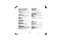
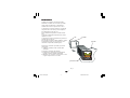
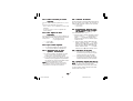
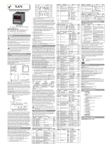
P31 = OFFSET applied to the measuredP31 = OFFSET applied to the measured
P31 = OFFSET applied to the measuredP31 = OFFSET applied to the measured
P31 = OFFSET applied to the measured
valuevalue
valuevalue
value
This will set a constant OFFSET throughout the
readout range. It is skipped for linear inputs
- For readout ranges with decimal figure, P31 is
programmable from -19.9 to 19.9.
- For readout ranges without decimal figure, P31
is programmable from -199 to 199.
P32 = Displayable protected parametersP32 = Displayable protected parameters
P32 = Displayable protected parametersP32 = Displayable protected parameters
P32 = Displayable protected parameters
This parameter is skipped when P18 = 0.
Off = Protected parameters cannot be
displayed.
On = Protected parameter can be displayed.
P33 = SMART functionP33 = SMART function
P33 = SMART functionP33 = SMART function
P33 = SMART function
O =SMART function disabled.
1 = SMART function in NOT protected by safety
lock.
2 =SMART function is under safety lock
protection.
Real curve
Readout
Adjusted
curve
Input
P31
LFSSV-1-D0.pmd 11/01/2011, 13.4415

16
GBGB
GBGB
GB
P34 =P34 =
P34 =P34 =
P34 =
Maximum value of the proportionalMaximum value of the proportional
Maximum value of the proportionalMaximum value of the proportional
Maximum value of the proportional
band calculated by the SMARTband calculated by the SMART
band calculated by the SMARTband calculated by the SMART
band calculated by the SMART
algorithm.algorithm.
algorithm.algorithm.
algorithm.
This parameter is skipped if P33=0.
It is programmable from P35 value to 200.0 %.
P35 =P35 =
P35 =P35 =
P35 =
Minimum value of the proportionalMinimum value of the proportional
Minimum value of the proportionalMinimum value of the proportional
Minimum value of the proportional
band calculated by the SMARTband calculated by the SMART
band calculated by the SMARTband calculated by the SMART
band calculated by the SMART
algorithmalgorithm
algorithmalgorithm
algorithm
This parameter is skipped if P33=0.
It is programmable from 1.0 % to P34 value.
P36 =P36 =
P36 =P36 =
P36 =
Minimum value of the integral timeMinimum value of the integral time
Minimum value of the integral timeMinimum value of the integral time
Minimum value of the integral time
calculated by the SMARTcalculated by the SMART
calculated by the SMARTcalculated by the SMART
calculated by the SMART
algorithm.algorithm.
algorithm.algorithm.
algorithm.
This parameter is skipped if P33=0.
It is programmable from 1 second (00.01) to 2
minutes (02.00).
P37 =P37 =
P37 =P37 =
P37 =
Relative cooling gain calculated byRelative cooling gain calculated by
Relative cooling gain calculated byRelative cooling gain calculated by
Relative cooling gain calculated by
SMART function.SMART function.
SMART function.SMART function.
SMART function.
This parameter available only when device is
configured with two control output and P33 is
different from 0.
Off = SMART algorithm does not calculate the
rC parameter value
On = SMART algorithm calculates the rC
parameter value.
P38 = MANUAL functionP38 = MANUAL function
P38 = MANUAL functionP38 = MANUAL function
P38 = MANUAL function
Off = manual function is disabled
On
= manual function can be enabled/
disabled by MAN pushbutton or by
contact closure on logic input 2.
P39 =P39 =
P39 =P39 =
P39 =
Device status at instrument startDevice status at instrument start
Device status at instrument startDevice status at instrument start
Device status at instrument start
up.up.
up.up.
up.
This parameter is skipped when P38 = Off .
O = the instrument starts in AUTO mode.
1 = the instrument starts in manual mode.
If the time proportioning output is
configured, the power output will be set to 0.
If servomotor control is configured, the
instrument will not modify the valve position.
2 = It starts in the same way it was prior to the
power shut down.
If the time proportioning output is configured
and the instrument was in manual mode, the
power output will be set to 0.
If servomotor control is configured and the
instrument was in manual mode, the instru-
ment will not modify the valve position.
3 = It starts in the same way it was prior to the
power shut down.
If: - the time proportioning output is
configured
- the instrument was in manual mode
the power output will be set equal to the last
value prior to power shut down.
If: - servomotor control is configured
- the instrument was in manual mode
- P40 = "bUmp"
the instrument will not modify the valve
position.
If: - servomotor control is configured
- the instrument was in manual mode
- P40 is different from "bUmp"
the instrument will modify the valve position in
order to reach the value set in P40.
LFSSV-1-D0.pmd 11/01/2011, 13.4416

17
GBGB
GBGB
GB
P40 = Transfer from AUTO to MANUALP40 = Transfer from AUTO to MANUAL
P40 = Transfer from AUTO to MANUALP40 = Transfer from AUTO to MANUAL
P40 = Transfer from AUTO to MANUAL
This parameter is skipped if P38 = OFF
When P5 = "smOL" and P6 = "no.fb", this parameter
is forced to "bUmp" and it cannot be modified.
- When the device is configured for one control
output, P40 can be set from 0 to 100
- When device is configured for two control
outputs, P40 can be set from -100 to 100.
Above the 100 value the instrument will show
"bUmp" and the transfer will be bumpless (the
manual mode starts with an output value equal to
the last value in the auto mode)
NOTENOTE
NOTENOTE
NOTE: If P40 is different from "bUmp" and an open
loop servomotor control with feedback
potentiometer is programmed, the instrument will
reach the P40 value using the feedback
indication.
P41 = Conditions for output safety valueP41 = Conditions for output safety value
P41 = Conditions for output safety valueP41 = Conditions for output safety value
P41 = Conditions for output safety value
When P5 is different from "sm.Ol" the P41 possible
selections are:
0 = No safety value ("Standard" effect)
1 = Safety value applied when overrange or
underrange condition is detected.
2 = Safety value applied when overrange
condition is detected.
3 = Safety value applied when underrange
condition is detected.
When P5 is equal to "sm.Ol" the P41 possible
selections are:
0 = No safety value ("Standard" effect)
4 = When an overrange or an underrange
condition is detected the instrument will close
the OUT 1 () relay contact.
5 = When an overrange or an underrange
condition is detected the instrument will close
the OUT 2 () relay contact.
6 = When an overrange or an underrange
condition is detected the instrument will revert
the "standard" effect.
NOTENOTE
NOTENOTE
NOTE: For "Standard effect" see chapter "Error
messages".
P42 = Output safety valueP42 = Output safety value
P42 = Output safety valueP42 = Output safety value
P42 = Output safety value
This parameter is skipped when P41 = 0, 4, 5 or 6.
This value can be set
- from 0 to 100 % when one control output is configured
- from -100 % to 100 % when two control outputs
are configured.
P43 = Digital filter on the displayedP43 = Digital filter on the displayed
P43 = Digital filter on the displayedP43 = Digital filter on the displayed
P43 = Digital filter on the displayed
valuevalue
valuevalue
value
It is possible to apply to the displayed value a
digital filter of the first order with a time constant
equal to :- 4 s for TC inputs
- 2 s for linear inputs
nO.Fl. = no filter
fltr. = filter enabled
P44 =P44 =
P44 =P44 =
P44 =
Control action typeControl action type
Control action typeControl action type
Control action type
p.I.D. - the instrument operates with a PID algorithm.
p.I. - the instrument operates with a PI algorithm.
P45 =P45 =
P45 =P45 =
P45 =
Operative set point alignement atOperative set point alignement at
Operative set point alignement atOperative set point alignement at
Operative set point alignement at
instrument start up.instrument start up.
instrument start up.instrument start up.
instrument start up.
0 = The operative set point will be aligned to SP or
SP2 according to the status of the logic inputs
1 and the set of P50.
1 = The operative set point will be aligned to the
measured value and then it will reach the
selected set point with a programmable ramp
(see Grd1 and Grd2 operative parameters).
NOTENOTE
NOTENOTE
NOTE: if the instrument detects an out of range or
an error condition on the measured value it will
ever operate as P45 = 0.
LFSSV-1-D0.pmd 11/01/2011, 13.4417
La pagina si sta caricando...
La pagina si sta caricando...
La pagina si sta caricando...
La pagina si sta caricando...
La pagina si sta caricando...
La pagina si sta caricando...
La pagina si sta caricando...
La pagina si sta caricando...
La pagina si sta caricando...
La pagina si sta caricando...
La pagina si sta caricando...
La pagina si sta caricando...
La pagina si sta caricando...
La pagina si sta caricando...
La pagina si sta caricando...
La pagina si sta caricando...
La pagina si sta caricando...
La pagina si sta caricando...
La pagina si sta caricando...
La pagina si sta caricando...
La pagina si sta caricando...
La pagina si sta caricando...
La pagina si sta caricando...
La pagina si sta caricando...
La pagina si sta caricando...
La pagina si sta caricando...
La pagina si sta caricando...
La pagina si sta caricando...
La pagina si sta caricando...
La pagina si sta caricando...
La pagina si sta caricando...
La pagina si sta caricando...
La pagina si sta caricando...
La pagina si sta caricando...
La pagina si sta caricando...
La pagina si sta caricando...
La pagina si sta caricando...
La pagina si sta caricando...
La pagina si sta caricando...
La pagina si sta caricando...
La pagina si sta caricando...
La pagina si sta caricando...
La pagina si sta caricando...
La pagina si sta caricando...
La pagina si sta caricando...
La pagina si sta caricando...
La pagina si sta caricando...
La pagina si sta caricando...
La pagina si sta caricando...
La pagina si sta caricando...
La pagina si sta caricando...
La pagina si sta caricando...
La pagina si sta caricando...
La pagina si sta caricando...
La pagina si sta caricando...
La pagina si sta caricando...
La pagina si sta caricando...
La pagina si sta caricando...
La pagina si sta caricando...
La pagina si sta caricando...
La pagina si sta caricando...
-
 1
1
-
 2
2
-
 3
3
-
 4
4
-
 5
5
-
 6
6
-
 7
7
-
 8
8
-
 9
9
-
 10
10
-
 11
11
-
 12
12
-
 13
13
-
 14
14
-
 15
15
-
 16
16
-
 17
17
-
 18
18
-
 19
19
-
 20
20
-
 21
21
-
 22
22
-
 23
23
-
 24
24
-
 25
25
-
 26
26
-
 27
27
-
 28
28
-
 29
29
-
 30
30
-
 31
31
-
 32
32
-
 33
33
-
 34
34
-
 35
35
-
 36
36
-
 37
37
-
 38
38
-
 39
39
-
 40
40
-
 41
41
-
 42
42
-
 43
43
-
 44
44
-
 45
45
-
 46
46
-
 47
47
-
 48
48
-
 49
49
-
 50
50
-
 51
51
-
 52
52
-
 53
53
-
 54
54
-
 55
55
-
 56
56
-
 57
57
-
 58
58
-
 59
59
-
 60
60
-
 61
61
-
 62
62
-
 63
63
-
 64
64
-
 65
65
-
 66
66
-
 67
67
-
 68
68
-
 69
69
-
 70
70
-
 71
71
-
 72
72
-
 73
73
-
 74
74
-
 75
75
-
 76
76
-
 77
77
-
 78
78
-
 79
79
-
 80
80
-
 81
81


in altre lingue
- English: Eurotherm LFS Servo User guide
Documenti correlati
-
Eurotherm TKS Guida utente
-
-
-
-
-
-
Eurotherm LHL Guida utente
-
-
-
Altri documenti
-
Omega CN3240 Series Manuale del proprietario
-
 CET LFP41 Manuale del proprietario
-
Ascon tecnologic D1 Manuale utente
-
gefran 600 Manuale utente
-
-
red lion IMP Manuale utente
-
-
 Rockwell Automation Allen-Bradley 900-TC32 Manuale utente
-
 ASCON TECNOLOGIC S.r.l. TLK72 Quick Manual
-
MD Sports TTT215_138M Guida utente


