Viessmann 5545 Manuale del proprietario
- Categoria
- Accessori per la preparazione del caffè
- Tipo
- Manuale del proprietario

Bedienungsanleitung
Operation Manual
Innovation,
die bewegt!
5545
Tasten-Stellpult 4-begriffig
Push-button panel 4-aspect
1. Wichtige Hinweise / Important information ........................................................ 2
2. Einleitung / Introduction ..................................................................................... 2
3. Anschluss / Connection ..................................................................................... 3
4. Gewährleistung / Warranty ................................................................................ 4
5. Technische Daten / Technical data .................................................................... 4

2
DE EN
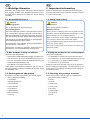
1. Wichtige Hinweise
Bitte lesen Sie vor der ersten Anwendung des Produktes
bzw. dessen Einbau diese Bedienungsanleitung auf-
merksam durch. Bewahren Sie diese auf, sie ist Teil des
Produktes.
1.1 Sicherheitshinweise
Vorsicht:
Verletzungsgefahr!
Für die Montage sind Werkzeuge nötig.
Stromschlaggefahr!
Die Anschlussdrähte niemals in eine Steckdose einfüh-
ren! Verwendetes Versorgungsgerät (Transformator,
Netzteil) regelmäßig auf Schäden überprüfen. Bei Schä-
den am Versorgungsgerät dieses keinesfalls benutzen!
Alle Anschluss- und Montagearbeiten nur bei abgeschal
-
teter Betriebsspannung durchführen!
Ausschließlich nach VDE/EN gefertigte Modellbahn-
transformatoren verwenden!
Stromquellen unbedingt so absichern, dass es bei einem
Kurzschluss nicht zum Kabelbrand kommen kann.
1.2 Das Produkt richtig verwenden
Dieses Produkt ist bestimmt:
- Zum Einbau in Modelleisenbahnanlagen und Dioramen.
- Zum Anschluss an einen Modellbahntransformator
(z. B. Art. 5200) bzw. an eine Modellbahnsteuerung mit
zugelassener Betriebsspannung.
- Zum Betrieb in trockenen Räumen.
Jeder darüber hinausgehende Gebrauch gilt als nicht be-
stimmungsgemäß. Für daraus resultierende Schäden haftet
der Hersteller nicht.
1.3 Packungsinhalt überprüfen
Kontrollieren Sie den Lieferumfang auf Vollständigkeit:
- Tasten-Stellpult4-begrig
- 2 Schrauben
- Verbindungselement
- 2 weiße Stecker
- 2 grüne Stecker
- 2 rote Stecker
- 2 gelbe Stecker
- Brauner Stecker
- Anleitung
1. Important information
Please read this manual completely and attentively be-
fore using the product for the rst time. Keep this manual.
It is part of the product.
1.1 Safety instructions
Caution:
Risk of injury!
Tools are required for installation.
Electrical hazard!
Never put the connecting wires into a power socket!
Regularly examine the transformer for damage. In case
of any damage, do not use the transformer.
Make sure that the power supply is switched o when
you mount the device and connect the cables!
Only use VDE/EN tested special model train transform-
ers for the power supply!
The power sources must be protected to avoid the risk
of burning cables.
1.2 Using the product for its correct purpose
This product is intended:
- For installation in model train layouts and dioramas.
- For connection to an authorized model train transformer
(e. g. item 5200) or a digital command station.
- For operation in dry rooms only.
Using the product for any other purpose is not approved
and is considered inappropriate. The manufacturer is not
responsible for any damage resulting from the improper
use of this product.
1.3 Checking the package contents
Check the contents of the package for completeness:
- Push-button panel 4-aspect
- 2 screws
- Connector
- 2 white plugs
- 2 green plugs
- 2 red plugs
- 2 yellow plugs
- 1 brown plug
- Manual

3
Sekundär
0-10-16 V~
16 V
Primär
230 V~
Gefertigt nach
VDE 0570
EN 61558
Lichttransformator
5200
Nur für trockene Räume
Primär 230 V 50 - 60 Hz
Sekundär max. 3,25 A52 VA
ta 25°CIP 40
10 V
0 V
rt1 wszum Gleis gn
Vorsignal -
Steuerung
rt2
viessmann
Steuermodul für
Licht-Ausfahrsignal 5223
16 V
bn ge
ge
viessmann 5545
Hp0 Hp1
Sh1 Hp2
Stellpult für Ausfahrsignale
+
-
DT
Verbindung bei
Dunkeltastung entfernen
Signalsteuerbaustein 5210
L+ ge1 ge2 gn1 gn2 rt1 rt2 gn ge ws
Viessmann
viessmann 5545
Hp0 Hp1
Sh1 Hp2
Stellpult für Ausfahrsignale
Hp0 Hp1
Sh1 Hp2
ge
rt
ws
gn
ge
rt
ws
gn
Fig. 1
Abb. 1
Hp0
Zughalt und
Rangierverbot
Stop and
shunting stop
Hp0/Sh1
Zughalt,
Rangierverbot
aufgehoben
Stop, proceed
shunting
Hp1
Fahrt
Proceed
Hp2
Langsamfahrt
Proceed slowly
2. Einleitung
Das Stellpult für Ausfahrsignale besitzt 8 separate Mo-
menttaster in 2 Gruppen für die Steuerung von bis zu 2
vierbegrigenLichtsignalen(Ausfahrsignale).JedeGruppe
besitzt 4 Taster.
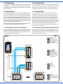
3. Anschluss
Das Stellpult allein ist nicht in der Lage, Lichtsignale anzu-
steuern. Erst durch den Anschluss eines Signal-Steuermo-
duls,(z.B.ViessmannArt.5210(ohneZugbeeinussung)
oderArt.5223(mitZugbeeinussung)sieheAbb.1),(Art.
5227 (für Ks-Signale) oder bistabile Relais, Art. 5552 siehe
Abb. 2) werden Spannungsimpulse des Stellpults in für die
Signale notwendige Dauerspannung umgewandelt und die
entsprechenden Signalbilder erzeugt.
Beachten Sie dazu auch auf jeden Fall die dem Steuermo-
dul und dem Signal beiliegenden Anleitungen!
3.1 Verbindung mehrerer Stellpulte
Mit dem jeweils beiliegenden Verbindungselement können
mehrere Viessmann-Stellpulte (Art. 5545, 5546, 5547,
5548, 5549) zu beliebig langen Funktionsgruppen zusam-
men gesteckt werden (siehe Abb. 1).
2. Introduction
The push-button panel for exit signals has got eight sepa-
rate momentary contacts for the switching of max. 2 four-
aspect colour light (exit-) signals. The push-buttons are
organized into two groups, each with four push-buttons.
3. Connection
The push-button panel on its own cannot control the
colour light signal. Only by connecting a signal control
module (e. g. Viessmann item 5210 (without signal de-
pendent train control) or item 5223 (with signal depend-
ent train control) as shown in g. 1), (item 5227 (for Ks-
signals) or solenoid relays, item 5552 as shown in g 2.)
the voltage pulses coming from the control panel are con-
verted into the required continuous output for the signals
and thus generate the appropriate signal aspects.
It is important to read the manuals provided with the con-
trol module and the signal!
3.1 Connecting several push-button panels
You can put several push-button panels together by us-
ing the enclosed connector. It is also possible to connect
other Viessmann push-button panels (items 5545, 5546,
5547, 5548, 5549) (see g. 1).

Modellbauartikel, kein Spielzeug! Nicht geeignet für
Kinder unter 14 Jahren! Anleitung aufbewahren!
Model building item, not a toy! Not suitable for children
under the age of 14 years! Keep these instructions!
Ce n’est pas un jouet! Ne convient pas aux enfants de moi-
ns de 14 ans! Conservez cette notice d’instructions!
Não é um brinquedo! Não aconselhável para menores de
14 anos! Conservar o manual de instruções!
Modelbouwartikel, geen speelgoed! Niet geschikt voor
kinderen onder 14 jaar! Gebruiksaanwijzing bewaren!
Articolo di modellismo, non è un giocattolo! Non adatto
a bambini al di sotto dei 14 anni! Conservare istruzioni per
l’uso!
Artículo para modelismo ¡No es un juguete! No
recomendado para menores de 14 años! Conserva las
instrucciones de servicio!
DE
EN
FR
NL
IT
ES
PT
Made in Europe
Viessmann
Modelltec
hnik GmbH
Bahnhofstraße 2a
D - 35116 Hatzfeld-Reddighausen
+49 6452 9340-0
www.viessmann-modell.de
4
92120
Stand 05/sw
10/2021
Ho/Kf
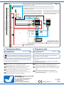
Fig. 2
Abb. 2
rt1
ws ge
gn
rt2
N2
bn ge
viessmann 5545
Hp0 Hp1
Sh1 Hp2
Stellpult für Ausfahrsignale
Elektr. Relais 5552
Viessmann
Elektr. Relais 5552
Viessmann
Die zweite Hälfte des Relais Art. 5552
kann für andere Zwecke genutzt werden.
The second half of the relay item 5552
can be used for other purposes.
Nur bei Hp0 wird der Fahrstrom im Halteabschnitt vor dem Signal abgeschal-
tet.Beidenanderen3SignalbegrienwirdderAbschnittüberdieRelaiskon-
takte mit Fahrstrom versorgt.
The driving current at the stop section will be switched o only when the signal
is showing “Hp0”. If the signal shows the three other aspects, the relay con-
tacts will power the section.
Dieser Schaltkontakt schaltet das Signal auto-
matisch auf Hp0, sobald der Zug es passiert hat.
This switching contact switches the signal auto-
matically to „Hp0“ after the train has passed it.
Schaltkontakt Art. 6840
Switching contact item 6840
mind. 1 Loklänge
at least 1 locomotive length
mind. 2 Loklängen
at least 2 locomotive lengths
Halteabschnitt / stop section
Gleichrichter-
dioden,
Art. 6834
Diodes,
item 6834
zum Fahrtransformator
to the regulating transformer
Signal-
standort
Signal
position
4. Technical data
max. switching voltage: 24V AC~ / DC=
max. contact load: 2A
4. Technische Daten
Max Schaltspannung: 24 V AC~ / DC=
Kontaktbelastbarkeit: 2A
Änderungen vorbehalten. Keine Haftung für Druckfehler und Irrtümer.
DieaktuelleVersionderAnleitungndenSieaufderViessmann
Homepage unter der Artikelnummer.
Subject to change without prior notice. No liability for mistakes and
printing errors.
You will nd the latest version of the manual on the Viessmann
website using the item number.
Entsorgen Sie dieses Produkt nicht über den (unsortierten)
Hausmüll, sondern führen Sie es der Wiederverwertung zu.
Do not dispose of this product through (unsorted) domestic
waste, supply it to recycling instead.
zum Transformator oder DC
Netzteil (braun: positiver Pol)
to transformer or DC power
supply (brown: positive pole)
-
 1
1
-
 2
2
-
 3
3
-
 4
4


Viessmann 5545 Manuale del proprietario
- Categoria
- Accessori per la preparazione del caffè
- Tipo
- Manuale del proprietario
in altre lingue
- English: Viessmann 5545 Owner's manual
- Deutsch: Viessmann 5545 Bedienungsanleitung
Documenti correlati
-
Viessmann 5223 Manuale del proprietario
-
Viessmann 5224 Manuale del proprietario
-
-
-
-
-
Viessmann 5221 Manuale del proprietario
-
-
-