Hangar 9 HAN4720 Manuale del proprietario
- Categoria
- Giocattoli telecomandati
- Tipo
- Manuale del proprietario
Questo manuale è adatto anche per

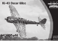
Ki-43 Oscar 60cc
Instruction Manual
Bedienungsanleitung
Manuel d’utilisation
Manuale di Istruzioni

2EN
NOTICE
All instructions, warranties and other collateral documents are subject to change at the sole discretion of Horizon
Hobby, LLC. For up-to-date product literature, visit horizonhobby.com or www.towerhobbies.com and click on the
support or resources tab for this product.
Age Recommendation: Not For Children Under 14 Years. This Is Not A Toy.
SAFETY WARNINGS AND PRECAUTIONS
Read and follow all instructions and safety precautions before use. Improper use can result in fi re, serious injury and
damage to property.
Components
Use only with compatible components. Should any compatibility questions exist, please refer to the product
instructions, component instructions or contact the appropriate Horizon Hobby offi ce.
Flight
Fly only in open areas to ensure safety. It is recommended fl ying be done at radio control fl ying fi elds. Consult local
ordinances before choosing a fl ying location.
Propeller
Always keep loose items that can become entangled in the propeller away from the prop. This includes loose clothing
or other objects such as pencils and screwdrivers. Keep your hands away from the propeller as injury can occur.
Batteries
Always follow the manufacturer’s instructions when using and disposing of any batteries. Mishandling of Li-Po
batteries can result in fi re causing serious injury and damage.
Small Parts
This kit includes small parts and should not be left unattended near children as choking and serious injury could result.
MEANING OF SPECIAL LANGUAGE
The following terms are used throughout the product literature to indicate various levels of potential harm when
operating this product:
WARNING: Procedures, which if not properly followed, create the probability of property damage, collateral damage,
and serious injury OR create a high probability of superfi cial injury.
CAUTION: Procedures, which if not properly followed, create the probability of physical property damage AND a
possibility of serious injury.
NOTICE: Procedures, which if not properly followed, create a possibility of physical property damage AND a little or
no possibility of injury.
WARNING: Read the ENTIRE instruction manual to become familiar with the features of the product before
operating. Failure to operate the product correctly can result in damage to the product, personal property and
cause serious injury.
This is a sophisticated hobby product. It must be operated with caution and common sense and requires some basic
mechanical ability. Failure to operate this Product in a safe and responsible manner could result in injury or damage
to the product or other property. This product is not intended for use by children without direct adult supervision. Do
not attempt disassembly, use with incompatible components or augment product in any way without the approval
of Horizon Hobby, LLC. This manual contains instructions for safety, operation and maintenance. It is essential to
read and follow all the instructions and warnings in the manual, prior to assembly, setup or use, in order to operate
correctly and avoid damage or serious injury.
SAFE OPERATING RECOMMENDATIONS
• Inspect your model before every fl ight to ensure it is airworthy.
• Be aware of any other radio frequency user who may present an interference problem.
• Always be courteous and respectful of other users in your selected fl ight area.
• Choose an area clear of obstacles and large enough to safely accomodate your fl ying activity.
• Make sure this area is clear of friends and spectators prior to launching your aircraft.
• Be aware of other activities in the vicinity of your fl ight path that could cause potential confl ict.
• Carefully plan your fl ight path prior to launch.
• Abide by any and all established AMA National Model Aircraft Safety Code.
BEFORE STARTING ASSEMBLY
• Remove parts from bag.
• Inspect fuselage, wing panels, rudder and stabilizer for damage.
• If you fi nd damaged or missing parts, contact your place of purchase.
• Charge transmitter and receiver batteries.
• Center trims and sticks on your transmitter.
• For a computer radio, create a model memory for this particular model.
• Bind your transmitter and receiver, using your radio system’s instructions.
NOTICE: Rebind the radio system once all control throws are set. This will keep the servos from moving to their
endpoints until the transmitter and receiver connect. It will also guarantee the servo reversal settings are saved in the
radio system.
FAA INFORMATION
If you own this product, you may be required to register with the FAA.
For up-to-date information on how to register with the FAA, please visit https://registermyuas.faa.gov/.
For additional assistance on regulations and guidance on UAS usage, visit knowbeforeyoufl y.org/.

3 EN
Ki-43 Oscar 60cc ARF
REQUIRED ADHESIVES
Description
15-minute epoxy
30-minute epoxy
Thin CA
Medium CA
Threadlock, low and high strength
Part # Description
HAN472001 KI-43 Oscar 60cc Airframe Only
HAN472002 Fuselage with Hatch: Ki-43 60cc
HAN472003 LH Wing with Aileron & Flap: Ki-43 60cc
HAN472004 RH Wing with Aileron & Flap: Ki-43 60cc
HAN472005 Stabilizer with Elevator: KI-43 60cc
HAN472006 Rudder: Ki-43 60cc
HAN472007 Cowling & Dummy Engine:Ki-43 60cc
HAN472008 Top Hatch: Ki-43 60cc
HAN472009 Canopy: Ki-43 60cc
HAN472010 Painted Pilot: Ki-43 60cc
HAN472011 Hardware Set: Ki-43 60cc
HAN472012 Mainwheels 5-inch: Ki-43 60cc
HAN472013 Tail Wheel Assembly: Ki-43 60cc
HAN472014 Pushrod Set: Ki-43 60cc
HAN472015 Spinner 3
3
/
4
-inch: Ki-43 60cc
HAN472016 Wing Tube: Ki-43 60cc
HAN472017 Fuel Tank: Ki-43 60cc
HAN472018 EP Motor Mount: Ki-43 60cc
HAN472019 Gear Door Set: Ki-43 60cc
HAN472020 Scale Details: Ki-43 60cc
HAN472025 Retract Set: Ki-43 60cc
HAN472026 Retracts and Struts: Ki-43 60cc
HAN472027 Air System Hardware: Ki-43 60 cc
HAN472028 Retract Struts: Ki-43 60cc
REPLACEMENT PARTS
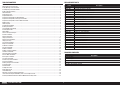
TABLE OF CONTENTS
Notice ......................................................................................................................................................................2
Meaning of Special Language ..................................................................................................................................2
Safety Warnings and Precautions .............................................................................................................................2
Safe Operating Recommendations ...........................................................................................................................2
Before Starting Assembly .........................................................................................................................................2
FAA Information .......................................................................................................................................................2
Replacement Parts ...................................................................................................................................................3
Required Adhesives .................................................................................................................................................3
Required for Completion, All Power Options ..............................................................................................................4
Required for Completion, Gas Engine Installation......................................................................................................4
Required for Completion, Electric Motor Installation .................................................................................................4
Optional Parts ..........................................................................................................................................................4
Tools Required .........................................................................................................................................................4
Printed Covering Notes ............................................................................................................................................5
Building Precautions ................................................................................................................................................5
Transportation and Storage ......................................................................................................................................5
Checking Blind Nuts.................................................................................................................................................5
Nose Weight ............................................................................................................................................................5
For the Visually Challenged ......................................................................................................................................5
Retract Installation ...................................................................................................................................................5
Aileron Installation ...................................................................................................................................................9
Hinging the Ailerons ...............................................................................................................................................11
Aileron Servo Installation .......................................................................................................................................12
Hinging the Flaps ...................................................................................................................................................14
Flap Servo Installation............................................................................................................................................15
Drop Tank Installation ............................................................................................................................................17
Stabilizer Installation ..............................................................................................................................................18
Elevator Installation ...............................................................................................................................................20
Rudder Installation .................................................................................................................................................21
Rudder Linkage Installation ....................................................................................................................................21
Tail Wheel Installation ............................................................................................................................................22
Pilot and Canopy Installation ..................................................................................................................................24
Electric Motor Installation .......................................................................................................................................25
Gas Engine Installation ...........................................................................................................................................27
Fuel Tank Installation .............................................................................................................................................29
Retract Air System Installation ...............................................................................................................................30
Receiver Installation ...............................................................................................................................................32
Cowling and Spinner Installation ............................................................................................................................32
Center of Gravity ....................................................................................................................................................34
Control Throws ......................................................................................................................................................35
Prefl ight Checklist ..................................................................................................................................................35
Daily Flight Checks ................................................................................................................................................35
Limited Warranty ...................................................................................................................................................35
Warranty and Service Contact Information .............................................................................................................36
Instructions for Disposal of WEEE by Users in the European Union ..........................................................................36
Academy of Model Aeronautics National Model Aircraft Safety Code .......................................................................37

4EN
REQUIRED FOR COMPLETION, GAS ENGINE INSTALLATION
REQUIRED FOR COMPLETION, ALL POWER OPTIONS
REQUIRED FOR COMPLETION, ELECTRIC MOTOR INSTALLATION
# Required Part # Description
2 SPMSA6110 A6110 M-T / M-S Standard HV Servo (throttle and choke)
1 DLEG0061 DLE-61cc Gas Engine w/Elec Ignition
1 DUB800 Tygon Gas Tubing, 3' Large
1 HAN116 Fuel Filler with “T" and Overfl ow Fittings
1 SPM9530 Spektrum 3-Wire Switch Harness
3 SPMB4000LPRX 4000mAh 2S 7.4V LiPo Rx Battery
# Required Part # Description
1 SPMAR12310T AR12310T 12CH PowerSafe Tele RX
7 SPMSA6320 A6320 H-T/H-S Brushless HV Servo
1 SPMSA6110 A6110 M-T / M-S Standard HV Servo (retract air valve)
2 SPMA3000 Heavy-Duty Servo Extension 3-inch
4 SPMA3002 Heavy-Duty Servo Extension 9-inch
# Required Part # Description
1 GPMG4805 Rimfi re 65cc Electric Motor
1 CSE010013100 Talon HV120 ESC 010-0131-00
TOOLS REQUIRED
Description
Adjustable wrench
Balancing stand
Box wrench: 14mm and 17mm
Crimping tool
Drill and tap set, metric
Drill bit set, Imperial or Metric
Epoxy brushes
Felt-tipped pen
Hemostats
Hex wrench set, Imperial and Metric
Hobby knife with #11 blade
Hobby scissors
Hook and loop straps
Hook and loop tape
Isopropyl alcohol
Light machine oil
Low-tack tape
Mixing sticks
Needle nose pliers
Nut driver set, Imperial and Metric
Paper towels
Pencil
Petroleum jelly
Phillips screwdriver: #1, #2
Pin vise
Razor saw
Rotary tool
Ruler
Sanding bar
Sanding drum for rotary tool
Sandpaper
Scissors
Side cutters
Square
Tap handle
Tapered reamer
Tie wraps
Toothpicks
Wire stripper
Part # Description
EVOA100 Optical Ignition Kill Switch
SAIEG90R3 FG-90R3 90cc 3-Cyl Radial Engine
SPMAS3000 AS3000 AS3X Stabilization Module
OPTIONAL PARTS

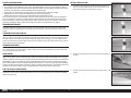
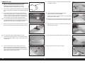
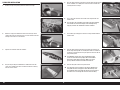
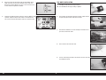
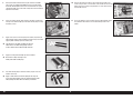
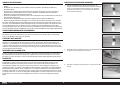
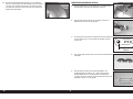
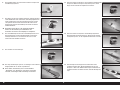
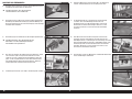
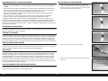
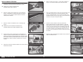
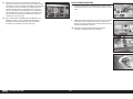
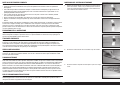
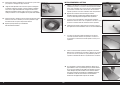
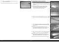
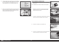
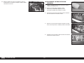
RETRACT INSTALLATION
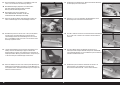
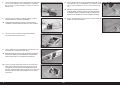
1. Use low-tack tape to mark the aileron, fl ap and retract covers so
they can be returned to the wing in the correct orientation. Use an
arrow pointing toward the leading edge as reference.
2. Remove the tape from the wing that secure the aileron and fl ap to
the wing.
3. Separate the aileron and fl ap from the wing. Set them aside in a safe
location.
5 EN
Ki-43 Oscar 60cc ARF
PRINTED COVERING NOTES
• The covering used on your model has the coloring and markings printed directly on the covering.
• The covering has a self-adhesive backing, and it is not recommended to use heat as it may damage the covering.
• Use only mild cleaning agents on the printed fi nish. Denatured alcohol is the most aggressive agent we recommend,
but test on an inconspicuous area fi rst. Prolonged use will remove the paint.
• Use tape with care. Anything other than low-tack tape can remove the fi nish, particularly on edges.
• Avoid contact with raw fuel, especially alcohol-based fuels containing nitro methane.
• Remove exhaust residue as soon as practical to avoid staining or damaging of the fi nish.
There are two areas on your aircraft that will receive wear under normal use. The fi rst area is where the cowling fi ts
over the fuselage hatch, and where the wing fi ts into the fuselage. Placing a piece of clear tape on the wing where it
fi ts into the fuselage, and on the hatch underneath the cowling, will reduce the wear on the covering in these areas.
Sanding the inside of the cowling smooth will also help prevent wear of the covering under the cowling.
BUILDING PRECAUTIONS
Prepare the work surface prior to beginning the build. The surface should be soft and free of any sharp objects. We
recommend resting the airframe parts on a soft towel or pit mat to prevent scratching or denting the surface of the
aircraft.
TRANSPORTATION AND STORAGE
When transporting and storing your model, you will need a minimum of 70 inches (1.8m) in length, and 28 inches
(54cm) in height to accommodate the size of the fuselage. We also recommend the use of wing and stabilizer bags to
help protect these surfaces during transport and storage. The control horns and linkages can cause damage to other
surfaces even when placed in storage bags. Always transport and store the wings and stabilizer so the linkages do not
contact other panels to prevent damage.
CHECKING BLIND NUTS
When building the aircraft, you will be required to thread machine screws into blind nuts. We recommend pre-threading
the screws to make sure the blind nuts are clear of any debris. If the screws do not thread in easily, clear the threads
using the appropriate tap and tap handle.
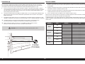
NOSE WEIGHT
This model will likely require the addition of nose weight to properly balance. Testing has been performed on all power
options. Using a heavier engine or motor will help in reducing the amount of weight required. Make sure to use proper
throttle management when fl ying with these larger and more powerful options. Our test aircraft with the recommended
Evolution® 62cc engine and muffl er, and receiver and ignition batteries under the fuel tank. Using engines other than
those recommended may require the additional weight to properly balance. This may vary from plane to plane. Add this
weight as far forward in the fuselage as possible to reduce the amount required to balance. This weight must be secure
so it does not come loose in fl ight, causing an unsafe model which could result in the loss of the aircraft.
FOR THE VISUALLY CHALLENGED
A copy of this manual can be found at www.horizonhobby.com under the tab for this particular model. Feel free to
download this manual and use a PDF viewer to zoom in on any text or images that may be in question when building
from the printed manual.

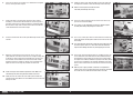
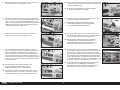
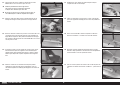
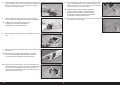
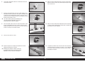
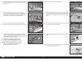
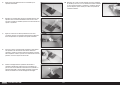
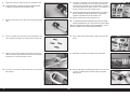
4. Use a hobby knife and #11 blade to remove the covering from the
retract openings in the wing. Trim the covering inside the opening.
5. Use low-tack tape to secure a piece of cardboard over the wing. This
will provide a place to rest the retract when routing the air lines and
prevent damage to the underside of the wing.
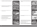
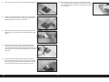
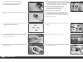
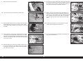
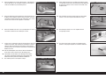
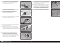
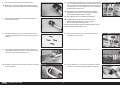
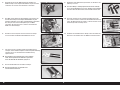
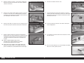
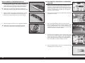
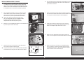
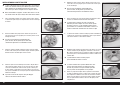
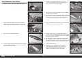
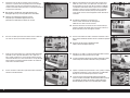
7. Cut a 19-inch (482mm) piece of the orange and blue air line. Attach
each air line to the retract. Using different colors makes connecting
the retracts correctly much easier when assembling the model.
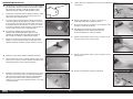
Use a heat gun on low to soften the air lines
slightly so they will slide on the fittings.
Make sure to orient the air line colors the same on both the
left and right retracts so they operate in the same manner.
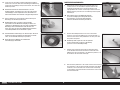
8. Route the air lines into the wing.
6. Use a pin vise and 1/8-inch (3mm) drill bit to make a hole in the
retract well for the air line.
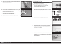
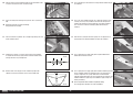
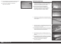
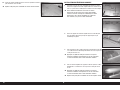
9. Both air lines can be retrieved at the fl ap servo opening. Use a piece
of low-tack tape to secure the lines together so they don’t fall back
into the wing.
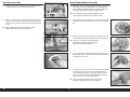
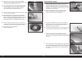
10. Fit the retract in the wing. Trim as necessary to provide clearance.
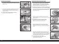
12. Place a lock washer on the M4 x 25 button head cap screw. Prepare
four screws at this time.
13. Use the M4 x 25 button head cap screws to secure the retract in the
wing. Place a drop of threadlock on each of the screws before their
installation. Tighten the screws using a 2.5mm hex wrench.
The cardboard can be removed from the wing
after the retract has been secured.
It may be necessary to use spacers under the retract frame to
make sure there is no torsional stress when tightened into position.
Torsional stress can cause intermittent operation of the retract unit.
11. The air lines can now be retrieved at the wing root.
6EN

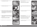
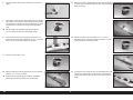
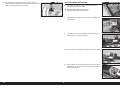
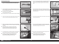
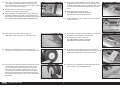
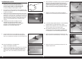
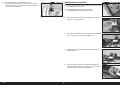
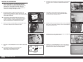
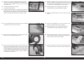
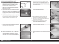
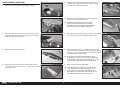
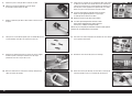
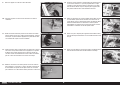
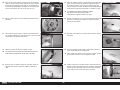
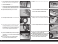
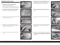
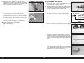
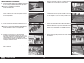
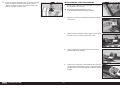
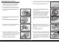
14. Place a drop of light machine oil on the M6 x 55 socket head cap
screw that will function as the wheel axle.
15. Slide the M6 x 55 socket head cap screw through the wheel. Make
sure the wheel spins freely on the screw.
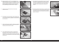
17. Position the gear door mount near the wheel as close to the wheel
as possible. The fl at area will align with the bottom of the wing. Use
an M3 x 5 setscrew and 1.5mm hex wrench to secure the position of
the gear door mount.
Do not over tighten the screws or use threadlock as it
will damage the composite material of the mounts.
18. Position the upper mount 2
3
/
4
inches (70mm) from the lower mount.
16. Thread the screw into the retract. Tighten the screw enough that the
wheel can spin freely, yet there isn’t any excess movement of the
wheel on the screw. Once set, use an M3 x 5 setscrew and 2mm hex
wrench to tighten the setscrew. Use a drop of threadlock on both
the M6 x 55 socket head cap screw and M3 x 5 setscrew to prevent
them from vibrating loose.
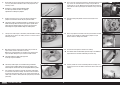
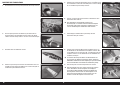
19. Use an M3 x 5 setscrew and 1.5mm hex wrench to secure the
position of the gear door mount.
Do not over tighten the screws or use threadlock as it
will damage the composite material of the mounts.
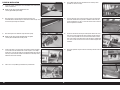
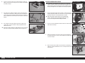
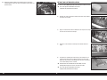
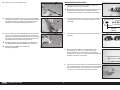
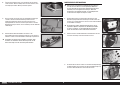
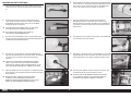
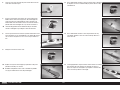
20. Tape a piece of paper to the wing that will go over the upper mount.
Rub a pencil on the paper to reveal the locations for the mounting
holes.
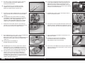
22. Attach the gear door to the mount using two M3 x 12 button head
screws and a 2mm hex wrench.
Check the positioning of the door to make sure it is centered
in the opening and aligns with the opening near the wheel.
Do not over tighten the screws or use threadlock as it
will damage the composite material of the mounts.
23. Use a felt-tipped pen to mark the location for the upper gear door
mounting screws on the gear door.
21. Use a drill and 1/8-inch (3mm) drill bit to drill the holes for the lower
gear mounting holes in the gear door.
7 EN
Ki-43 Oscar 60cc ARF

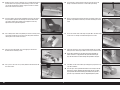
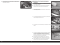
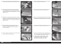
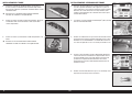
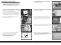
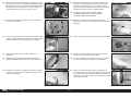
24. Remove the cover and use a drill and 1/8-inch (3mm) drill bit to drill
the two holes for the upper gear door mounting screws. The door
can now be attached to the mounts using the four M3 x 12 button
head screws and 2mm hex wrench.
25. If the gear door is not fl ush with the bottom of the wing, the mounts
may need to be adjusted. The mounting area for the lower mount
can also be sanded using medium grit sandpaper to make any
adjustments to the gear door alignment.
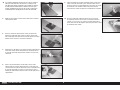
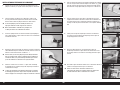
27. Place the cover into position. Use a felt-tipped pen to mark the
locations for the mounting screws
28. Use a pin vise and 1/16-inch (1.5mm) drill bit to drill the mounts for
the retract covers.
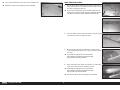
26. Use a hobby knife or other sharp tool to puncture the covering at the
screw holes that will secure the cover to the wing. Also remove the
covering to clear the retract mechanism.
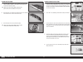
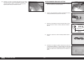
29. Thread an M2 x 10 sheet metal screw into each hole using a #1
Phillips screwdriver. Remove the screws before proceeding.
30. Apply a small amount of thin CA to harden the threads made in the
previous step. Allow the CA to fully cure before installing the retract
cover.
31. Secure the retract cover to the wing using four M2 x 10 sheet metal
screws. Use a #1 Phillips screwdriver to tighten the screws.
32. Check that the retract can be fully extended without the gear door
hitting the cover. Trim the gear door as necessary if it hits the cover.
There will be movement in the gear during their operation so
make sure there is a gap between the gear door and wing so
they do not contact each other during the operation of the gear.
33. Use hobby scissors and medium grit sandpaper to prepare the hub
caps for installation.
The hub caps can be painted if desired. Be sure to fully scuff and
prepare the surface. Applying paint directly to the hub cap with
no preparation will result in flaking paint. Always test paint on a
piece of scrap material to check its compatibility to the plastic.
8EN

34. Use contact adhesive to glue the hub cap to the wheel. Use low-tack
tape to hold the hub cap in position until the adhesive fully cures.
Repeat this section to install the remaining retract assembly.
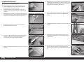
AILERON INSTALLATION
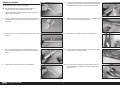
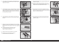
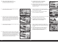
1. Use medium-grit sandpaper to lightly sand the control horn where
it fi ts into the control surface. Clean the sanded area using a paper
towel and isopropyl alcohol to remove any debris or oils. This
provides the surface texture necessary for the epoxy to bond to.
Use tape on the painted area to help prevent removing
the exposed portion of the control horn. Remove the
tape once the control horn has been sanded.
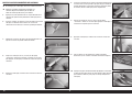
2. Insert the M3 x 10 button head screw into the hole in the control
horn. Remove any paint using a hobby knife and #11 blade so the
screw fi ts into the hole easily. Check all the control horns.
The hole should be just large enough for the screw to slide
through, yet still fit snugly in the hole and not move excessively.
4. Test fi t the control horn in the slot. Do not force the control horn into
the slot. Use a square to make sure the control horn is square to the
control surface. Do not force the control horn in the slot.
If the control horn fits tight, or is not square, use a rotary tool
3/32-inch (2.5mm) drill bit to carefully enlarge and reshape
the hole. Wrap a piece of low-tack tape around the drill
bit to set the depth of the drill bit so it won’t accidentally
pass through the opposite side of the control surface.
3. Run your fi nger along the bottom of the aileron to locate the area
for the control horn. Use a hobby knife and #11 blade to remove the
covering, exposing the slots for the control horn.
9 EN
Ki-43 Oscar 60cc ARF

5. Place tape around the slot in the aileron for the aileron control horn.
6. Remove the control horns from the control surfaces. Apply epoxy to
the slot in the aileron. Make sure the epoxy gets into the slot for a
good bond between the surfaces and control horn.
8. Before the epoxy fully cures, remove the tape from around the
control horn. This will allow the epoxy to fl ow around the control
horn, creating a small fi llet between the control horn and surface for
a fi nished look and secure bond. Allow the epoxy to fully cure before
proceeding.
9. Test fi t the remaining control horn. When gluing the control horn,
place the ball end between the horns and insert the M3 x 10 button
head screw through the control horns and rod ends. This will align
the horns correctly, making the linkage installation easier later.
7. Apply epoxy to the area of the control horn that fi ts into the slot. Use
enough epoxy so the control horn will be fully bonded to the control
surfaces.
10. Once the epoxy has fully cured, pull on the control horn to make
sure it is glued securely in the aileron. If not, remove the control horn
and sand off any adhesives. Repeat this section to glue the control
horn in the aileron.
10EN

HINGING THE AILERONS
Do not mix any epoxy until instructed to do so.
Use the short hinges for the ailerons. The longer hinges are
used for the flaps due to the hinging technique used.
1. Apply a small amount of oil to the fl ex point of the hinge to prevent
epoxy from entering the hinge.
2. Insert the hinge so the center of the hinge point aligns with the front
edge of the bevel on the control surface. Check that the hinge can
move freely.
3. Position the hinge so it is perpendicular to the hinge line when fully
defl ected.
6. Insert the hinges into the control surface. Verify the hinge position
is correct. Use a paper towel and isopropyl alcohol to remove any
excess epoxy. Allow the epoxy to fully cure before proceeding.
7. Mix 1/2 ounces (15mL) of 30-minute epoxy. Use a toothpick to apply
epoxy inside each of the holes for the hinges.
4. Mix 1/2 ounces (15mL) of 30-minute epoxy. Remove the hinges,
then use a toothpick to apply epoxy inside each of the holes for the
hinges.
5. Apply epoxy to the outside of the hinge using a toothpick
9. Fit the aileron to the wing. Check that the aileron can move freely,
and the hinges are all aligned properly.
8. Apply epoxy to the outside of the hinge using a toothpick
10. Use a paper towel and isopropyl alcohol to remove any excess
epoxy. Use low-tack tape to hold the aileron in position until the
epoxy fully cures.
11 EN
Ki-43 Oscar 60cc ARF

11. Once the epoxy has fully cured, pull on the wing and aileron to make
sure the hinges are glued securely. If not, remove the aileron and
sand off any adhesives. Repeat this section to glue the hinges.
AILERON SERVO INSTALLATION
1. Use a hobby knife and #11 blade to remove the covering for the
aileron pushrod exit.
2. Center the aileron servo. Attach the servo horn on the servo
perpendicular to the servo centerline.
3. When attaching the linkage to the aileron servo arm, use the hole in
the arm that is 5/8-inch (16mm) from the center of the arm.
4. Prepare both the left and right aileron servos at this time.
5. Assemble the linkage for the aileron using two ball ends and the
3
15
/
16
inch (100mm) threaded rod. Thread each ball end 12 turns
on the link. Adjust the length so the distance between the ball ends
measures 3
5
/
32
inches (80mm).
12EN
5/8 inch
(16mm)

6. Secure the servo ball link to the servo arm using an M3 x 10 button
head screw, M3 washer and M3 lock nut. Use a 2.5mm hex wrench
and 5.5mm nut driver to tighten the hardware.
11. Secure the servo ball link to the control horn using an M3 x 10
button head screw, M3 washer and M3 lock nut. Use a 2.5mm hex
wrench and 5.5mm nut driver to tighten the hardware.
Connect the servo to the radio system to hold the aileron servo in
the centered position. Disconnect the ball from the control horn
and adjust the linkage so the aileron is in the neutral position.
Reinstall the hardware once the linkage has been adjusted.
12. Use the steps outlined for the retract cover to install the aileron
cover.
7. Secure a 6-inch (150mm) servo extension to the servo using a
commercially available retainer (SPMA3054).
The length of the extension may vary depending on servo selection.
The extension listed works with the recommended servos.
8. Tie or tape the string located inside the wing to the end of the servo
lead.
9. Use the string to pull the servo lead through the wing and out at the
root.
We left a small amount of the string on the aileron
servo lead so it can be quickly differentiated between
the flap servo lead that will be installed later.
10. Install the aileron servo in the wing with the output facing the
leading edge. Make sure to prepare the servo mounting holes by
threading a servo mounting screw into each hole and removing
them. Harden the mounting screw locations with thin CA before
installing the servo.
13 EN
Ki-43 Oscar 60cc ARF

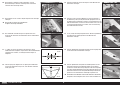
HINGING THE FLAPS
The flaps must be positioned to the wing before the epoxy
begins to cure. Make sure to read through all the steps
before mixing any epoxy. Glue only one flap at a time to
allow enough working time to properly install the hinges.
1. Locate the fl ap control horns. When installed, the concave portion of
the horn (as indicated in the drawing) will face toward the top of the
fl aps.
6. The fl ap will also align to the bottom of the wing when the hinges
are positioned correctly.
8. Apply epoxy to each hinge where it will be inserted into the fl ap.
Insert the hinges in the fl ap.
Use 15-minute or 30-minute epoxy to allow enough
working time during the hinge installation.
7. Remove the fl ap from the wing and remove the hinges. Apply epoxy
into each of the holes in the fl ap.
Do not use an excessive amount of epoxy when gluing the hinges.
Use enough epoxy to securely adhere the hinges to the surfaces.
2. Run your fi nger down the leading edge of the fl ap to locate the
area for the fl ap control horns. Use a hobby knife and #11 blade to
remove the covering, exposing the slots for the control horn. Use
15-minute epoxy to glue the fl ap control horns in position. Remove
any excess epoxy using a paper towel and isopropyl alcohol.
Use the steps outlined for the aileron control horns to install the
flap control horns. Make sure to check that the flap control horns
are glued securely in the flaps once the adhesive fully cures.
9. Apply epoxy to each hinge where it will be inserted into the wing.
10. Apply epoxy into each of the holes in the wing.
3. Wrap a piece of low-tack tape around the fl ap to create a tab so the
fl ap can be lifted and lowered into position when fi tting the hinges.
Use the long hinges when installing the flaps to the wing.
4. Test fi t the hinges to the fl ap. Do not use any adhesives now. Slide
the hinge into position. Position as shown, checking to make sure it
can move freely.
5. Check the fi t of the fl ap to the wing. It will fi t centered in the
opening. The hinge pin will be positioned directly over the gap
between the leading edge of the fl ap and the aft edge of the wing
opening. Test the operation of the fl ap to make sure the hinges are
properly aligned and the fl ap movies freely.
14EN

11. Fit the fl ap to the wing. Check that the fl ap can move freely, and the
hinges are all aligned properly. Use low-tack tape to hold the fl ap in
position until the epoxy fully cures.
12. Use a paper towel and isopropyl alcohol to remove any excess epoxy
before it can fully cure. Use care not to get epoxy in the moving part
of the hinge or between the fl ap and wing. Continue once the epoxy
has fully cured for both sets of fl ap hinges.
Make sure to check that the flap hinges are glued
securely once the adhesive has fully cured.
Repeat this section for the remaining flap hinge installation.
FLAP SERVO INSTALLATION
1. Center the fl ap servo. Attach the servo horn on the servo
perpendicular to the servo centerline.
We recommend setting the throws to 0% for radios
using a three-position switch to prevent damaging the
servo if the linkage is not the correct length.
2. When attaching the linkage to the aileron servo arm, use the hole in
the arm that is 5/8-inch (16mm) from the center of the arm.
4. Assemble the linkage for the fl ap using two ball ends and the 4
23
/
32
inch (120mm) threaded rod. Thread each ball end 12 turns on
the link. Adjust the length so the distance between the ball ends
measures 4
1
/
4
inches (108mm).
5. Remove the servo arm from the servo. Secure the servo ball link
to the servo arm using an M3 x 10 button head screw, M3 washer
and M3 lock nut. Use a 2.5mm hex wrench and 5.5mm nut driver to
tighten the hardware.
3. Prepare both the left and right fl ap servos at this time.
15 EN
Ki-43 Oscar 60cc ARF
5/8 inch
(16mm)

6. The ball link will be attached to the underside of the servo arm as
shown.
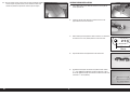
11. Move the servo to the UP fl ap position using the radio system. Adjust
the throws at the radio system to bring the fl ap in alignment with the
bottom of the wing.
12. Move the servo to the FULL fl ap position of
1
31
/
32
–2
3
/
8
inches
(
50–60mm) using the radio system. Adjust the throws in the radio
system to obtain the measurements listed.
13. The linkage may rub against the wing structure depending on servo
selection. Use a hobby knife with a #11 blade or a rotary tool and
sanding drum to trim the wing structure as necessary to clear the
linkage.
7. Install the fl ap servo in the wing with the output facing the leading
edge. Make sure to prepare the servo mounting holes by threading
a servo mounting screw into each hole and removing them. Harden
the mounting screw locations with thin CA before installing the
servo.
The flap servos can be positioned in the wing to allow the
use of a Y-harness to connect the servos to the receiver.
8. Secure the servo ball link to the control horn using an M3 x 10
button head screw, M3 washer and M3 lock nut. Use a 2.5mm hex
wrench and 5.5mm nut driver to tighten the hardware.
9. Attach the servo arm to the servo.
10. Adjust the length of the linkage to position the fl ap in the mid fl ap
position of 1–
1
3
/
16
inches (25–30mm).
Remember to set the throws to 0% in both the up and down
positions to prevent damage to the servo, flap or linkage.
16EN

14. Use the steps outlined for the retract cover to install the fl ap cover.
Repeat this section for the remaining flap servo installation.
DROP TANK INSTALLATION
1. Run your fi nger along the bottom of the wing to locate the blind nuts
for the drop tank mount. Use a hobby knife and #11 blade to remove
the covering, exposing the blind nuts.
Thread a screw into the blind nuts by hand first to make sure the
threads are clear. Cross threading, stripping, or damaging the blind
nuts withing the wing will require considerable work to rectify.
2. Thread the drop tank mounts into the blind nuts in the pylons. Do not
over-tighten the mounts and damage the pylon.
3. Attach the pylon to the wing using two M4 x 15 socket head cap
screws and two M4 lock washers. Use a 3mm hex wrench to tighten
the screws.
Place a drop of canopy glue on each screw before
their installation. This will keep them from vibrating
loose yet leave them easily removable.
4. Attach the drop tank to the mounts using four M3 x 12 button head
screws. Use a 2mm hex wrench to tighten the screws.
Place a drop of canopy glue on each screw before
their installation. This will keep them from vibrating
loose yet leave them easily removable.
Repeat this section for the remaining
drop tank installation.
17 EN
Ki-43 Oscar 60cc ARF

STABILIZER INSTALLATION
1. Remove the tape and packing materials from the fuselage.
2. Move the canopy latch toward the front of the fuselage. Lift the
canopy hatch from the fuselage at the rear and remove it from the
fuselage. Set it aside in a safe location.
5. Run your fi nger along the sides of the fuselage to locate the opening
for the stabilizer. Use a hobby knife and #11 blade to remove the
covering from the fuselage.
6. Use a razor saw to remove the section of the tail post from the
stabilizer slot.
The tail post is left in position at the factory to prevent damage
and maintain the structural integrity of the fuselage during
shipping and must be removed to install the stabilizer.
7. Use medium grit sandpaper to sand the fuselage smooth with the
stabilizer slot.
3. Separate the elevators from the stabilizer. 8. Run your fi nger along the top of the wing to locate the blind nut
for the wing retaining bolt. Use a hobby knife with a #11 blade to
remove the covering from the wing to expose the blind nut for the
wing retaining bolt.
For additional security, glue can be applied to the blind
nut on the inside of the wing. Epoxy with micro balloons
to thicken it works well for this task. Make sure not to
get any adhesive inside the threads of the blind nut.
9. Slide the wing tube into the wing tube socket.
The wing tube may be a tight fit in the socket. Polishing the
wing tube with fine sand paper or steel wool will help ease
the installation of the wing tube. Do not force the wing tube in
the socket as it can damage the structure inside the wing.
4. Run your fi nger along the bottom of the stabilizer to locate the
center. Use a hobby knife and #11 blade to remove the covering
from the center section.
18EN

10. Slide the wing panel into position. Guide the fl ap and aileron leads,
as well as the retract air lines, into the fuselage.
11. Secure the wing to the fuselage using the 1/4-20 x 1 nylon wing
bolt.
Repeat the steps to secure the remaining
wing panel on the fuselage.
15. Use a felt-tipped pen to transfer the fuselage outline onto the top of
the stabilizer.
16. Use a ruler and a hobby knife with a #11 blade to carefully cut the
covering 1/8 inch (3 mm) inside the line drawn on the top of the
stabilizer to remove the covering from the center of the stabilizer.
Use care not to cut into the underlying wood, weakening the
stabilizer.
18. Use an epoxy brush to apply epoxy to the exposed wood on the
bottom of the stabilizer as well.
17. Mix 3/4 ounce (25ml) of 30-minute epoxy. Use an epoxy brush to
apply epoxy to the exposed wood on the top of the stabilizer.
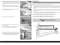
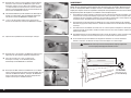
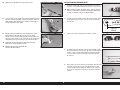
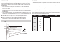
12. Place the stabilizer in position. Use a straight edge to align the rear
of the stabilizer and fi n.
13. Stand back 8-10 feet (2-3 meters) and check that the stabilizer
is aligned with the wing. Lightly sand the stabilizer saddle on the
fuselage to correct any misalignment.
14. Measure from each wing tip to each stabilizer tip. Adjust the
stabilizer so the measurements are the same for both sides.
19. Use an epoxy brush to apply epoxy to the stabilizer mounting surface
for the stabilizer. Position the stabilizer back on the fuselage and
check its alignment. Use a paper towel and a small amount of
isopropyl alcohol to remove any excess epoxy from the fuselage and
stabilizer before the epoxy fully cures. Allow the epoxy to fully cure
before proceeding.
Check the position of the stabilizer repeatedly during
the curing process to make sure it has not moved.
19 EN
Ki-43 Oscar 60cc ARF
A=A
AA
AA
A=A

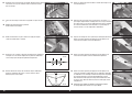
ELEVATOR INSTALLATION
1. Install the elevator control horns. Their installation is the same as the
aileron control horns.
Make sure to check that the control horns are
securely glued before proceeding.
2. Glue the hinges in the elevator using 30-minute epoxy. The
installation of the elevator hinges is similar to the aileron hinges. Use
the short hinges to hinge the elevators
3. Glue the hinges to the stabilizer using 30-minute epoxy.
Make sure to check that the elevator hinges are glued
securely once the adhesive has fully cured.
6. Use a hobby knife with a #11 blade to trim the covering so the
pushrod can exit the fuselage.
7. Thread a ball end 12 turns on the pushrod. Secure the servo ball
link to the control horn using an M3 x 10 button head screw, M3
washer and M3 lock nut. Use a 2.5mm hex wrench and 5.5mm nut
driver to tighten the hardware.
8. Center the elevator servo using the radio system. Attach the servo
horn on the servo perpendicular to the pushrod. Thread a ball end
12 turns on the pushrod. Secure the servo ball link to the control
horn using an M3 x 10 button head screw, M3 washer and M3 lock
nut. Use a 2.5mm hex wrench and 5.5mm nut driver to tighten the
hardware.
9. Repeat the previous steps to install the remaining elevator servo and
pushrod.
4. Prepare the holes in the fuselage for the elevator servo by threading
a screw into each hole. Remove the screws and place 2 to 3 drops
of thin CA in each hole to harden the surrounding wood. Once the CA
has fully cured, install the elevator servo with the servo output shaft
toward the front of the fuselage.
5. Slide a 36
5
/
8
inch (930mm) pushrod into the pushrod tube.
20EN
La pagina si sta caricando...
La pagina si sta caricando...
La pagina si sta caricando...
La pagina si sta caricando...
La pagina si sta caricando...
La pagina si sta caricando...
La pagina si sta caricando...
La pagina si sta caricando...
La pagina si sta caricando...
La pagina si sta caricando...
La pagina si sta caricando...
La pagina si sta caricando...
La pagina si sta caricando...
La pagina si sta caricando...
La pagina si sta caricando...
La pagina si sta caricando...
La pagina si sta caricando...
La pagina si sta caricando...
La pagina si sta caricando...
La pagina si sta caricando...
La pagina si sta caricando...
La pagina si sta caricando...
La pagina si sta caricando...
La pagina si sta caricando...
La pagina si sta caricando...
La pagina si sta caricando...
La pagina si sta caricando...
La pagina si sta caricando...
La pagina si sta caricando...
La pagina si sta caricando...
La pagina si sta caricando...
La pagina si sta caricando...
La pagina si sta caricando...
La pagina si sta caricando...
La pagina si sta caricando...
La pagina si sta caricando...
La pagina si sta caricando...
La pagina si sta caricando...
La pagina si sta caricando...
La pagina si sta caricando...
La pagina si sta caricando...
La pagina si sta caricando...
La pagina si sta caricando...
La pagina si sta caricando...
La pagina si sta caricando...
La pagina si sta caricando...
La pagina si sta caricando...
La pagina si sta caricando...
La pagina si sta caricando...
La pagina si sta caricando...
La pagina si sta caricando...
La pagina si sta caricando...
La pagina si sta caricando...
La pagina si sta caricando...
La pagina si sta caricando...
La pagina si sta caricando...
La pagina si sta caricando...
La pagina si sta caricando...
La pagina si sta caricando...
La pagina si sta caricando...
La pagina si sta caricando...
La pagina si sta caricando...
La pagina si sta caricando...
La pagina si sta caricando...
La pagina si sta caricando...
La pagina si sta caricando...
La pagina si sta caricando...
La pagina si sta caricando...
La pagina si sta caricando...
La pagina si sta caricando...
La pagina si sta caricando...
La pagina si sta caricando...
La pagina si sta caricando...
La pagina si sta caricando...
La pagina si sta caricando...
La pagina si sta caricando...
La pagina si sta caricando...
La pagina si sta caricando...
La pagina si sta caricando...
La pagina si sta caricando...
La pagina si sta caricando...
La pagina si sta caricando...
La pagina si sta caricando...
La pagina si sta caricando...
La pagina si sta caricando...
La pagina si sta caricando...
La pagina si sta caricando...
La pagina si sta caricando...
La pagina si sta caricando...
La pagina si sta caricando...
La pagina si sta caricando...
La pagina si sta caricando...
La pagina si sta caricando...
La pagina si sta caricando...
La pagina si sta caricando...
La pagina si sta caricando...
La pagina si sta caricando...
La pagina si sta caricando...
La pagina si sta caricando...
La pagina si sta caricando...
La pagina si sta caricando...
La pagina si sta caricando...
La pagina si sta caricando...
La pagina si sta caricando...
La pagina si sta caricando...
La pagina si sta caricando...
La pagina si sta caricando...
La pagina si sta caricando...
La pagina si sta caricando...
La pagina si sta caricando...
La pagina si sta caricando...
La pagina si sta caricando...
La pagina si sta caricando...
La pagina si sta caricando...
La pagina si sta caricando...
La pagina si sta caricando...
La pagina si sta caricando...
La pagina si sta caricando...
La pagina si sta caricando...
La pagina si sta caricando...
La pagina si sta caricando...
La pagina si sta caricando...
La pagina si sta caricando...
La pagina si sta caricando...
La pagina si sta caricando...
La pagina si sta caricando...
La pagina si sta caricando...
La pagina si sta caricando...
-
 1
1
-
 2
2
-
 3
3
-
 4
4
-
 5
5
-
 6
6
-
 7
7
-
 8
8
-
 9
9
-
 10
10
-
 11
11
-
 12
12
-
 13
13
-
 14
14
-
 15
15
-
 16
16
-
 17
17
-
 18
18
-
 19
19
-
 20
20
-
 21
21
-
 22
22
-
 23
23
-
 24
24
-
 25
25
-
 26
26
-
 27
27
-
 28
28
-
 29
29
-
 30
30
-
 31
31
-
 32
32
-
 33
33
-
 34
34
-
 35
35
-
 36
36
-
 37
37
-
 38
38
-
 39
39
-
 40
40
-
 41
41
-
 42
42
-
 43
43
-
 44
44
-
 45
45
-
 46
46
-
 47
47
-
 48
48
-
 49
49
-
 50
50
-
 51
51
-
 52
52
-
 53
53
-
 54
54
-
 55
55
-
 56
56
-
 57
57
-
 58
58
-
 59
59
-
 60
60
-
 61
61
-
 62
62
-
 63
63
-
 64
64
-
 65
65
-
 66
66
-
 67
67
-
 68
68
-
 69
69
-
 70
70
-
 71
71
-
 72
72
-
 73
73
-
 74
74
-
 75
75
-
 76
76
-
 77
77
-
 78
78
-
 79
79
-
 80
80
-
 81
81
-
 82
82
-
 83
83
-
 84
84
-
 85
85
-
 86
86
-
 87
87
-
 88
88
-
 89
89
-
 90
90
-
 91
91
-
 92
92
-
 93
93
-
 94
94
-
 95
95
-
 96
96
-
 97
97
-
 98
98
-
 99
99
-
 100
100
-
 101
101
-
 102
102
-
 103
103
-
 104
104
-
 105
105
-
 106
106
-
 107
107
-
 108
108
-
 109
109
-
 110
110
-
 111
111
-
 112
112
-
 113
113
-
 114
114
-
 115
115
-
 116
116
-
 117
117
-
 118
118
-
 119
119
-
 120
120
-
 121
121
-
 122
122
-
 123
123
-
 124
124
-
 125
125
-
 126
126
-
 127
127
-
 128
128
-
 129
129
-
 130
130
-
 131
131
-
 132
132
-
 133
133
-
 134
134
-
 135
135
-
 136
136
-
 137
137
-
 138
138
-
 139
139
-
 140
140
-
 141
141
-
 142
142
-
 143
143
-
 144
144
-
 145
145
-
 146
146
-
 147
147
-
 148
148


Hangar 9 HAN4720 Manuale del proprietario
- Categoria
- Giocattoli telecomandati
- Tipo
- Manuale del proprietario
- Questo manuale è adatto anche per
in altre lingue
- English: Hangar 9 HAN4720 Owner's manual
- français: Hangar 9 HAN4720 Le manuel du propriétaire
- Deutsch: Hangar 9 HAN4720 Bedienungsanleitung
Documenti correlati
-
 Hangar 9 HAN5280 Manuale del proprietario
-
 Hangar 9 HAN2890 Manuale del proprietario
-
 Hangar 9 HAN3390 Manuale utente
-
 Hangar 9 HAN2530 Manuale del proprietario
-
 Hangar 9 HAN4670 Manuale del proprietario
-
 Hangar 9 HAN5260 Manuale del proprietario
-
 Hangar 9 HAN4770 Manuale del proprietario
-
 Hangar 9 HAN2390 Manuale del proprietario
-
 Hangar 9 HAN3185 Manuale del proprietario
-
 Hangar 9 HAN2990 Manuale del proprietario


Altri documenti
-
E-flite Habu 32x DF Manuale utente
-
Kyosho 11892 Manuale utente
-
-
-
Blade BLH4925SC Manuale del proprietario
-
-
Garmin Piloto automatico eyector Reactor 40 Guida d'installazione
-
Petsafe PPA19-16145 Guida Rapida
-
 Next Level Racing NLR-S026 Manuale utente
-
Endura Ultimate Multi-Point Astragal Istruzioni per l'uso
