
1
P200 Series
MANUALE D’USO E MANUTENZIONE
USE AND MAINTENANCE MANUAL
BEDIENUNGS - UND WARTUNGSANLEITUNG
MANUEL D’EMPLOI ET D’ENTRETIEN
MANUAL DE USO Y MANTENIMIENTO
P200
Automatismo per Cancelli a Battente - Uso Residenziale/Condominiale
Swing Gate Operator - Residential/Communities
Drehtorantrieb für Privat und Gewerbe
Automatisme pour Portails à Battant – Usage Résidentiel/Intensif
Accionador para Puertas Batientes – Uso Residencial/Comunidades
Via Enrico Fermi, 43 - 36066 Sandrigo (VI) Italia
Tel +39 0444 750190 - Fax +39 0444 750376 - info@tauitalia.com - www.tauitalia.com
IT - Istruzioni originali
D_MNL0P200 19-05-2010 - Rev.17

2
P200 Series
Italiano
Español
English
Français
Deutsch
I dati riportati nel presente manuale sono puramente indicativi. La TAU si riserva il diritto di modicarli in qualsiasi momento.
La Casa costruttrice si riserva il diritto di apportare modiche o miglioramenti al prodotto senza alcun preavviso. Eventuali imprecisioni o
errori riscontrabili nel presente fascicolo, saranno corretti nella prossima edizione.
All’apertura dell’imballo vericare che il prodotto sia integro. Riciclare i materiali secondo la normativa vigente.
L’installazione del prodotto dovrà essere effettuata da personale qualicato. La Ditta costruttrice Tau declina ogni responsabilità
per danni derivanti a cose e/o persone dovuti ad un’eventuale errata installazione dell’impianto o la non messa a Norma dello
stesso secondo le vigenti Leggi (vedi Direttiva Macchine).
Los datos describidos en este manual son puramente indicativos. La TAU se reserva el derecho de modicarlos en cualquier momento.
El Fabricante se reserva el derecho de modicar o actualizar el producto sin aviso previo. Posibles imprecisiones o errores en este
manual serán corregidos en la próxima edición.
Cuando abra el embalaje, controle que el producto esté íntegro. Recicle los materiales según la normativa vigente.
La instalación del producto tiene que ser efectuada por personal cualicado. El Fabricante Tau no se asume ninguna
responsabilidad por lesiones a personas o averías a cosas causadas por una instalación incorrecta del equipo o la por la
inobservancia de la normativa vigente (véase Directiva de Máquinas).
The data described in this handbook are purely a guide. TAU reserves the right to change them in any moment.
The manufacturer reserves the right to modify or improve products without prior notice. Any inaccuracies or errors found in this handbook
will be corrected in the next edition.
When opening the packing please check that the product is intact. Please recycle materials in compliance with current regulations.
This product may only be installed by a qualied tter. The manufacturer declines all liability for damage to property and/or
personal injury deriving from the incorrect installation of the system or its non-compliance with current law (see Machinery
Directive).
Les données décrites dans ce manual sont purement indicatives. La TAU se réserve le droit de les modier à n’importe quel moment.
Le Constructeur se réserve le droit d’apporter des modications ou des améliorations au produit sans aucun préavis. Les éventuelles
imprécisions ou erreurs présentes dans ce fascicule seront corrigées dans la prochaine édition.
À l’ouverture de l’emballage, vérier que le produit est intact. Recycler les matériaux suivant les normes en vigueur.
L’installation du produit devra être effectuée par du personnel qualié. Tau décline toute responsabilité pour les dommages
aux choses et/ou personnes dus à une éventuelle installation erronée de l’automatisme ou à la non-mise aux normes suivant
les lois en vigueur (voir Directive Machines).
Die beschriebenen Daten in der vorliegenden Betriebsanleitung sind rein indikativ. TAU behält sich vor, diese in jedem Moment zu
modizieren.
Der Hersteller behält sich das Recht vor, ohne vorherige Benachrichtung Änderungen oder Verbesserungen am Produkt anzubringen.
Ungenauigkeiten oder Fehler, die in der vorliegenden Ausgabe festgestellt werden, werden in der nächsten Ausgabe berichtigt.
Beim Öffnen der Verpackung prüfen, dass das Produkt keine Schäden aufweist. Die Materialien nach den gültigen Vorschriften
recyclen.
Die Installation des Produktes muss von Fachpersonal ausgeführt werden. Die Herstellerrma TAU übernimmt keinerlei Haftung
für Personen- und/oder Sachschäden aufgrund einer falschen Installation der Anlage oder der Nichtkonformität derselben mit
den gültigen Gesetzen (siehe Maschinenrichtlinie).

3
P200 Series
AVVERTENZE E ISTRUZIONI PER L’INSTALLATORE
Tau si congratula per la scelta del prodotto e vi invita a leggere con molta attenzione queste pagine.
Al ne di renderle semplici, le istruzioni sono state impaginate seguendo l’ordine delle varie fasi d’installazione dell’impianto.
Leggere attentamente le istruzioni prima di procedere all’installazione, in quanto forniscono importanti indicazioni concernenti la
sicurezza, l’installazione, l’uso e la manutenzione.
Tutto quello che non è espressamente previsto nel presente manuale NON è permesso. Consultare la TAU srl per ogni cosa non indicata.
Usi non indicati, infatti, potrebbero essere causa di danni al prodotto stesso e mettere in pericolo persone, animali e/o cose.
L’installazione deve essere eseguita da personale qualicato, professionalmente competente.
L’installazione, i collegamenti elettrici e le regolazioni devono essere effettuati nell’osservanza della Buona Tecnica e in ottemperanza alle
norme vigenti.
Prima di iniziare l’installazione vericare l’integrità del prodotto.
Non installare il prodotto in ambiente e atmosfera esplosivi.
Prima di installare l’automazione, apportare tutte le modiche strutturali relative alla realizzazione dei franchi di sicurezza ed alla protezione
o segregazione di tutte le zone di schiacciamento, cesoiamento, convogliamento e di pericolo in genere. Vericare che la struttura esistente
abbia i necessari criteri di robustezza e stabilità. Per la messa a punto della coppia massima del motoriduttore, attenersi alle normative in
vigore (per l’Europa consultare le norme prEN 12341 e prEN 12635).
L’installazione del motoriduttore, ad eccezione dei modelli interrati, deve essere realizzata sopra il livello del pavimento, al ne di evitare
rischi di allagamento.
I dispositivi di sicurezza (fotocellule, coste sensibili, stop di emergenza, ecc.) devono essere installati tenendo in considerazione: le normative
e le direttive in vigore, i criteri della Buona Tecnica, l’ambiente di installazione, la logica di funzionamento del sistema e le forze sviluppate
dalla porta o cancello motorizzati.
Scegliere percorsi brevi per i cavi. Tenere separati i cavi di potenza dai cavi di comando.
Quantunque il motoriduttore possa essere dotato di tutti i dispositivi di sicurezza si consiglia caldamente di tenere fuori della portata di
bambini o di persone inabili ogni dispositivo in grado di comandare l’apertura del cancello e che possa inavvertitamente essere usato senza
sorveglianza.
Applicare le segnalazioni previste dalle norme vigenti per individuare le zone pericolose. Ogni installazione deve riportare in modo visibile
l’indicazione dei dati identicativi degli organi automatizzati.
Prima di collegare l’alimentazione elettrica accertarsi che i dati di targa siano rispondenti a quelli della rete di distribuzione elettrica.
Prevedere sulla rete di alimentazione un interruttore/sezionatore onnipolare con distanza d’apertura dei contatti uguale o superiore a 3
mm.
Vericare che a monte dell’impianto elettrico vi siano un interruttore differenziale e una protezione di sovracorrente adeguati (interruttore
magnetotermico C6).
Collegare l’automazione ad un efcace impianto di messa a terra eseguito come previsto dalle vigenti norme di sicurezza.
Il costruttore dell’automazione declina ogni responsabilità qualora vengano installati elementi incompatibili ai ni della sicurezza e del buon
funzionamento. Per l’eventuale riparazione o sostituzione dei prodotti, dovranno essere utilizzati esclusivamente ricambi originali.
L’installatore deve fornire tutte le informazioni relative al funzionamento automatico, manuale e di emergenza della struttura automatizzata,
e consegnare all’utilizzatore dell’impianto le istruzioni per l’uso.
Consigliamo di riporre tutta la documentazione relativa all’impianto all’interno o nelle immediate vicinanze della centralina.
Italiano
WARNINGS AND INSTRUCTIONS FOR FITTERS
Congratulations on choosing this Tau product. Please read this handbook carefully.
For the sake of simplicity, the instructions are listed in order of installation.
Please read these instructions carefully before installing the product as they contain important information concerning safety,
installation, use and maintenance.
Anything not expressly specied in this handbook is FORBIDDEN. Contact TAU srl for information regarding any points which may not
have been specied in the present manual.
Operations not indicated in these instructions may damage the product and put people, animals and/or and property at risk.
The equipment should be installed only by trained and qualied personnel.
Installation, electrical connections and adjustments must be made according to the rules of good workmanship and current standards.
Before beginning installation, make sure the product is undamaged.
Do not install the product in explosive environments.
Prior to installing the automation, make all structural modications in order to ensure safety distances and protect and segregate areas in
which people may be exposed to the risk of crushing, shearing, dragging or similar dangers. Make sure the existing structure is sufciently
sturdy and stable. Observe current legislation when adjusting maximum gearmotor torque (in Europe consult prEN 12341 and prEN
12635 standards).
Apart from buried models, the gearmotor must be installed above ground level in order to prevent damage deriving from ooding.
The safety devices (photocells, sensitive edges, emergency stop devices, etc.) must be installed according to current legislation and
directives, the rules of good workmanship, the installation area, the operating logic of the system and the forces developed by the
powered door or gate.
Choose short routes for the cables. Keep power cables separate from control cables.
Though the gearmotor is tted with various safety devices, we strongly recommend keeping all unattended devices capable of opening
the gate out of the reach of children or unable adults.
Fit the signs required by current regulations for identifying dangerous areas. Each installation must show the identication data of the
automated devices in a visible place.
Before connecting to the power supply, make sure the data on the rating plate correspond to the mains power supply.
Fit a multipole switch/knife switch on the power supply network with contacts opening distance of at least 3 mm.
Make sure there is a suitable circuit breaker and overcurrent protection device (thermal-magnet breaker C6) upline from the electrical
system.
Connect the automation to an efcient earth system compliant with current safety standards.
The manufacturer declines all liability if incompatible safety and components are installed. Only use original spare parts to repair or
replace the product.
The tter must provide all the information relative to the automatic, manual and emergency operation of the automated unit, and give the
user the operating instructions.
Keep all the documents concerning the system inside or near the central control unit.
English

4
P200 Series
AVERTISSEMENTS ET INSTRUCTIONS POUR L’INSTALLATEUR
Tau vous félicite de votre choix et vous invite à lire très attentivement les pages qui suivent.
An de faciliter la compréhension, l’ordre de présentation des instructions suit celui des différentes phases d’installation de l’automatisme.
Lire attentivement les instructions avant de procéder à l’installation, dans la mesure où elles fournissent des indications importantes
concernant la sécurité, l’installation, l’emploi et la maintenance.
Tout ce qui n’est pas expressément prévu dans ce manuel N’EST PAS permis. Consulter TAU srl pour tout ce qui n’est pas indiqué.
Les utilisations non indiquées, en effet, pourraient provoquer des dommages au produit et mettre en danger les personnes, les animaux et/ou
les choses.
L’installation doit être effectuée par du personnel qualié, professionnellement compétent.
L’installation, les connexions électriques et les réglages doivent être effectués dans les règles de l’art en respectant les normes en vigueur.
Avant de commencer l’installation, vérier l’intégrité du produit.
Ne pas installer le produit dans un environnement et une atmosphère explosifs.
Avant d’installer l’automatisme, apporter toutes les modications structurelles relatives à la réalisation des espaces de sécurité et à la protection
ou à l’isolement de toutes les zones d’écrasement, cisaillement et de danger en général. Vérier que la structure existante possède la robustesse
et la stabilité nécessaires. Pour le réglage du couple maximum du motoréducteur, respecter les normes en vigueur (pour l’Europe consulter les
normes prEN 12341 et prEN 12635).
L’installation du motoréducteur, à l’exception des modèles enterrés, doit être réalisée au-dessus du niveau du sol an d’éviter les risques
d’inondation.
Les dispositifs de sécurité (photocellules, barres palpeuses, arrêt d’urgence, etc.) doivent être installés en tenant compte : des normes et des
directives en vigueur, des règles de l’art, du site d’installation, de la logique de fonctionnement du système et des forces générées par la porte
ou le portail motorisés.
Choisir des parcours brefs pour les câbles et maintenir les câbles de puissance séparés des câbles de commande.
Malgré tous les dispositifs de sécurité qui peuvent équiper l’automatisme, il est vivement conseillé de maintenir hors de portée des enfants ou
de personnes inaptes tout dispositif en mesure de commander l’ouverture du portail et qui, par mégarde, pourrait être utilisé sans surveillance.
Appliquer les signalisations prévues par les normes en vigueur pour identier les zones dangereuses. Chaque installation doit reporter de
manière visible, l’indication des données d’identication des organes automatisés.
Avant de connecter l’alimentation électrique, s’assurer que les données de la plaque correspondent à celles du secteur de distribution électrique.
Prévoir sur le secteur d’alimentation un interrupteur/sectionneur omnipolaire avec distance d’ouverture des contacts égale ou supérieure à 3
mm.
Vérier qu’il y a en amont de l’automatisme un interrupteur différentiel et une protection contre la surcharge adéquats (interrupteur
magnétothermique C6).
Raccorder l’automatisme à une installation efcace de mise à la terre effectuée suivant les prescriptions des normes de sécurité en vigueur.
Le constructeur de l’automatisme décline toute responsabilité en cas d’installation de composants incompatibles en matière de sécurité et de
bon fonctionnement. Pour toute réparation ou pour tout remplacement des produits, il faudra utiliser exclusivement des pièces de rechange
originales.
L’installateur doit fournir toutes les informations relatives au fonctionnement automatique, manuel et d’urgence de la structure automatisée et
remettre à l’utilisateur de l’automatisme le mode d’emploi.
Nous conseillons de conserver toute la documentation relative à l’installation à l’intérieur de l’armoire de commande ou à proximité
immédiate.
HINWEISE UND ANWEISUNGEN FÜR DEN INSTALLATEUR
Tau gratuliert Ihnen zur Wahl dieses Produkts und bittet Sie, diese Seiten sehr aufmerksam zu lesen.
Um die Anweisungen einfach zu machen, wurden sie in der Reihenfolge der verschiedenen Installationsphasen der Anlage verfasst.
Die Anweisungen vor der Installation genau lesen, da sie wichtige Hinweise mit Bezug auf Sicherheit, Installation, Bedienung und
Wartung liefern.
Alles nicht ausdrücklich in diesen Anleitungen vorgesehene ist UNZULÄSSIG. Wenden Sie sich für alles nicht angegebene an die Firma TAU
srl.
Ein nicht angegebener Gebrauch könnte Schäden am Produkt verursachen und Personen, Tiere und/oder Gegenstände in Gefahr bringen.
Die Installation muss von beruich kompetentem Fachpersonal ausgeführt werden.
Installation, elektrische Anschlüsse und Einstellungen sind unter Beachtung der Fachtechnik und der gültigen Vorschriften auszuführen.
Das Produkt vor der Installation auf Schäden überprüfen.
Das Produkt nicht in EX-Umgebung bzw. EX-Atmosphäre installieren.
Vor der Installation der Automatisierung alle strukturellen Änderungen für das Vorhandensein der Sicherheitsabstände und den Schutz aller
Bereiche ausführen, in denen Quetsch-, Schnitt- und Mitnehmgefahr und Gefahren allgemein bestehen. Prüfen, ob die vorhandene Struktur
die erforderliche Robustheit und Stabilität besitzt. Für die Einstellung des maximalen Drehmoments des Getriebemotors sind die gültigen
Vorschriften zu beachten (für Europa siehe die Normen prEN 12341 und prEN 12635).
Die Installation des Getriebemotors muss, Unterurmodelle ausgenommen, über der Bodenhöhe erfolgen, um Überschwemmungsgefahr zu
vermeiden.
Sicherheitsvorrichtungen (Fotozellen, Sicherheitsleisten, Notstop usw.) müssen unter Berücksichtigung des folgenden installiert werden: gültige
Vorschriften und Verordnungen, korrekte Fachtechnik, Installationsumgebung, Betriebslogik des Systems und Kräfte, die vom motorbetriebenen
Tor entwickelt werden.
Kurze Strecken beim Verlegen der Kabel wählen. Leistungskabel von Steuerkabeln getrennt halten.
Auch wenn der Getriebemotor mit allen Sicherheitsvorrichtungen ausgestattet werden kann, empfehlen wir, Vorrichtungen zur Betätigung eines
Tors, die ohne Überwachung zufällig benutzt werden könnten, außer der Reichweite von Kindern oder Personen mit Handicaps zu halten.
Zur Kennzeichnung von Gefahrenbereichen die laut gültigen Vorschriften vorgesehenen Beschilderungen anbringen. An jeder Installation
müssen die Kenndaten der automatisierten Elemente sichtbar angegeben sein.
Vor dem Anschluss der Stromversorgung ist sicher zu stellen, dass die Kenndaten mit jenen des Stromnetzes übereinstimmen.
Am Versorgungsnetz einen allpoligen Schalter/Trennschalter mit Öffnungsabstand der Kontakte von oder über 3 mm vorsehen.
Prüfen, dass vor der elektrischen Anlage ein Differentialschalter und ein geeigneter Überstromschutz (magnetothermischer Schalter C6)
vorhanden sind.
Die Automatisierung an eine wirksame Erdungsanlage anschließen, die nach den gültigen Sicherheitsvorschriften ausgeführt ist.
Der Hersteller der Automatisierung übernimmt keinerlei Haftung, falls Bestandteile installiert werden, die – was Sicherheit und korrekten Betrieb
betrifft – nicht kompatibel sind. Zur Reparatur oder zum Ersatz der Produkte dürfen ausschließlich Originalersatzteile verwendet werden.
Der Installateur hat alle Auskünfte über den automatischen und manuellen Betrieb und den Notbetrieb der automatisierten Struktur zu liefern und
muss dem Benutzer der Anlage die Bedienungsanweisungen aushändigen.
Wir empfehlen, alle Unterlagen der Anlage in der Steuerzentrale oder in ihrer unmittelbaren Nähe aufzubewahren.
Deutsch
Français

5
P200 Series
ADVERTENCIAS E INSTRUCCIONES PARA EL INSTALADOR
Tau le agradece por la elección del producto y le invita a leer con mucha atención estas páginas.
A n de simplicar su uso, las instrucciones han sido compaginadas siguiendo el orden de las diferentes etapas de instalación del
sistema.
Lea con atención las instrucciones antes de proceder con la instalación, puesto que suministran importantes indicaciones
sobre la seguridad, instalación, uso y mantenimiento.
Todo aquello que no está expresamente previsto en este manual NO está permitido. Consulte con TAU srl para cualquier cosa que no
esté indicada.
En efecto, los usos no previstos podrían causar averías al producto y ser peligrosos para las personas, animales o cosas.
La instalación debe ser hecha por personal cualicado y experto.
La instalación, las conexiones eléctricas y las regulaciones deben ser efectuadas correctamente y respetando las normas vigentes.
Antes de empezar la instalación, controle la integridad del producto.
No instale el producto en locales con atmósfera explosiva.
Antes de instalar la automatización, realice todas las modicaciones estructurales relativas a la realización de las distancias de seguridad
y a la protección o separación de todas las zonas de aplastamiento, corte y peligro en general. Controle que la estructura existente posea
los criterios necesarios de robustez y estabilidad. Para poner a punto el par máximo del motorreductor, aténgase a las normativas en
vigor (para Europa consulte las normas prEN 12341 y prEN 12635).
La instalación del motorreductor, menos en el caso de los modelos enterrados, tiene que efectuarse por encima del nivel del
pavimento para evitar posibles inundaciones.
Los dispositivos de seguridad (fotocélulas, bordes sensibles, botón de parada de emergencia, etc.) se deben instalar teniendo en cuenta:
las normativas y directivas vigentes, los criterios de la buena técnica, el entorno de instalación, la lógica de funcionamiento del sistema
y las fuerzas desarrolladas por la puerta o cancela motorizadas.
Escoja recorridos cortos para los cables. Mantenga separados los cables de potencia de los cables de control.
Aunque el motorreductor disponga de todos los dispositivos de seguridad, se aconseja mantener fuera del alcance de los niños o de
personas incapacitadas cualquier dispositivo capaz de controlar la apertura de la cancela y que pueda utilizarse de forma inadvertida
sin vigilancia.
Aplique las señalizaciones previstas por las normas vigentes para señalar las zonas peligrosas. Cada instalación debe tener a la vista la
indicación de los datos de identicación de los componentes automatizados.
Antes de conectar la alimentación eléctrica, controle que las características nominales correspondan a aquellas de la red de distribución
eléctrica.
Prevea en la red de alimentación un interruptor omnipolar de 3 o más mm de apertura de los contactos.
Controle que antes de la instalación eléctrica haya un interruptor diferencial y un dispositivo de protección de sobrecorriente adecuados
(interruptor magnetotérmico C6).
Conecte la automatización a una instalación de puesta a tierra ecaz y que respete las normas de seguridad vigentes.
El fabricante de la automatización no se asume ninguna responsabilidad si se instalan componentes incompatibles para la seguridad y
el funcionamiento correcto. Para una posible reparación o sustitución de los productos, use sólo recambios originales.
El instalador debe suministrar todas las informaciones relativas al funcionamiento automático, manual y de emergencia de la estructura
automatizada, y entregar al usuario de la instalación las instrucciones para su uso.
Se aconseja guardar toda la documentación de la instalación en el interior o cerca de la central.
INDICE - INHALTSVERZEICHNIS - CONTENTS - INDEX – ÍNDICE
pag. 6 Caratteristiche tecniche della serie P200 - Technische Eigenschaften der serie P200 - Technical features of the P200 series
- Caractéristiques techinques de la série P200 - Características técnicas de la serie P200.
pag. 7 Italiano
pag. 9 English
pag. 11 Deutsch
pag. 13 Disegni - Drawings - Zeichnen - Projets - Dibujos
pag. 18 Français
pag. 20 Español
pag. 22 Esplosi della serie P200 - Exploded diagrams of the P200 series - Explosionszeichnungen der reihe P200 - Vues éclatées de
la série P200 - Despieces de la serie P200.
pag. 26 Dichiarazione di conformità - Declaration of conformity - Konformitäserklärung - Declaration de conformity - Declaración de
conformidad.
pag. 27 Garanzia - Garantie - Guarantee - Garantie - Garantía
Español

6
P200 Series
CARATTERISTICHE TECNICHE DELLA SERIE P200
TECHNICAL CHARACTERISTICS OF THE P200 SERIES
TECHNISCHE EIGENSCHAFTEN DER SERIE P200
CARACTÉRISTIQUES TECHNIQUES DE LA SÉRIE P200
CARACTERÍSTICAS TÉCNICAS DE LA SERIE P200
P225 P250 P270 P225BENC P250BENC P270BENC
Alimentazione \ Power input \ Versorgung \ Alimentation \
Alimentación
230 Vac ±10%
Alimentazione Motore \ Motor power input \ Motorversorgung \
Alimentation Moteur \ Alimentación motor
230 Vac ±10% 18 Vdc ±10%
Frequenza \ Frequency \ Frequenz \ Fréquence \ Frecuencia 50/60 Hz
Condensatore \ Capacitor \ Kondensator \ Condensateur \
Condensador
10 µf -
Corrente assorbita a vuoto \ Absorbed current (no load) \
Stromaufnahme (ohne Last) \ Courant absorbé (à vide) \ Corriente
absorbida (en vacío)
1,5 A ± 10% 0,8 A ± 10%
Potenza assorbita a vuoto \ Absorbed power (no load) \
Leistungsaufnahme (ohne Last) \ Puissance absorbée (à vide) \
Potencia absorbida (en vacío)
250 W 20 W
Velocità motore (a vuoto) \ Motordrehzahl (leer) \ Motor speed (no
load) \
Vitesse moteur (à vide) \ Velocidad motor (en vacío)
900 rpm 1500 rpm
Corsa utile \ Useful travel \ Arbeitshub \ Course utile \ Carretra útil 295 mm 435 mm 540 mm 295 mm 435 mm 540 mm
Intervento di termoprotezione \ Thermal protection trips at \
Auslösung des Wärmeschutzes \ Intervention protection thermique
\ Intervención de termoprotección
140 °C (autoripristino) -
Rapporto di riduzione \ Reduction ratio \ Untersetzungsverhältnis \
Rapport de réduction \ Relación de reducción
1/24
Temperatura di esercizio \ Operating temperature \
Betriebstemperatur \
Température de fonctionnement \ Temperatura de ejercicio
–20 °C ÷ +70 °C
Peso \ Weight \ Gewicht \ Poids \ Peso 7,8 Kg 8,1 Kg 10,4 Kg 7,8 Kg 8,1 Kg 10,4 Kg
IP Motore \ Motor IP \ Schutzart des Motors (IP) \ IP Moteur \ IP
Motor
IP 13
Ciclo di lavoro \ Work cycle \ Arbeitzzyklus \ Cycle de travail \ Ciclo
de trabajo
15 % 100 %
Tempo corsa 90° \ 90° travel time \ Laufzeit, 90° \
Temps de course 90° \ Tiempo recorrido 90°
19 sec. 22 sec. 25 sec. 9 - 12 sec. 11 - 14 sec. 13 - 16 sec.
NOTA: QUANDO IL SISTEMA IN 12 VDC È ALIMENTATO UNICAMENTE DALLA BATTERIA (IN CASO DI BLACK-OUT OPPURE IN
ABBINAMENTO CON PANNELLO FOTOVOLTAICO), LE PRESTAZIONI ESPRESSE DAL MOTORIDUTTORE (FORZA E VELOCITÀ)
SI RIDUCONO DEL 30% CA.
N.B. WHEN THE SYSTEM IS IN THE 12 V DC MODE AND IS POWERED BY THE BATTERY ONLY (IN THE EVENT OF A POWER
FAILURE OR WHEN USED IN CONJUNCTION WITH A PHOTOVOLTAIC PANEL), THE GEAR MOTOR’S OUTPUT (POWER AND
SPEED) IS REDUCED BY APPROXIMATELY 30% .
ANMERKUNG: WENN DAS 12 VDC SYSTEM NUR ÜBER BATTERIE GESPEIST IST (BEI STROMAUSFALL ODER IN
KOMBINATION MIT EINEM PHOTOVOLTAICPANEEL), VERRINGERN SICH DIE LEISTUNGEN DES GETRIEBEMOTORS (KRAFT
UND GESCHWINDIGKEIT) UM CA. 30%.
ATTENTION : QUAND LE SYSTÈME À 12 VCC EST ALIMENTÉ UNIQUEMENT PAR LA BATTERIE (EN CAS DE COUPURE DE
COURANT OU BIEN EN ASSOCIATION AVEC UN PANNEAU PHOTOVOLTAÏQUE), LES PERFORMANCES DU MOTORÉDUCTEUR
(FORCE ET VITESSE) DIMINUENT D’ENVIRON 30% .
NOTA: CUANDO EL SISTEMA DE 12 VDC ES ALIMENTADO ÚNICAMENTE POR LA BATERÍA (EN CASO DE CORTE DE CORRIENTE,
O BIEN COMBINADO CON PANEL FOTOVOLTAICO), LAS PRESTACIONES DEL
MOTORREDUCTOR (FUERZA Y VELOCIDAD) SE REDUCEN EN UN 30%.
I - N.B.: In presenza di vento, per l’installazione su cancelli ad ante battenti
cieche, non è garantito il funzionamento.
GB - N.B.: For The installation of blank swing gates, functioning cannot be
gua-ranteed in the presence of wind.
D - N.B.: Bei Wind wird für die Installation an durchgehenden Flügel-toren
der Betrieb nicht garantiert.
F - N.B.: En présence de vent, en cas d’installation sur des portails avec
portes battantes pleines, le fonctionnement n’est pas garanti.
E - N.B.: En presencia de viento, para la instalación en cancelas de hojas
batientes cie-gas, no se garantiza el funcionamiento.
P200
P225
P225BENC
P250
P250BENC
P270
P270BENC

7
P200 Series
DIMENSIONI - g. 1
MATERIALI PER L’INSTALLAZIONE - g. 2
1_ Art.P-2250SP190 : staffa piccola zincata
2_ Art.M-V400008035 : vite zincata M8 x 35
3_ Art.-- : attuatore serie P200 o P200BENC
4_ Art.P-2250SG190 : staffa grande zincata
5_ Art.P-700PA1 : staffa angolare zincata
6_ Art.M-0300000040 : condensatore cilindrico 10 µf
INSTALLAZIONE - g. 3
CONSIDERAZIONI PRELIMINARI
Rispettare i valori di tabella . Se si deve far riferimento ad angoli
diversi utilizzare il metodo pratico descritto nel paragrafo “operazioni
preliminari” di “FISSAGGIO STAFFA PICCOLA”.
Oliare i cardini del cancello.
Fissare la angia piccola sulla struttura portante del cancello.
Nota: per una completa sicurezza si fa obbligo di installare,
se non presenti, i fermi meccanici (battenti a pavimento) con
tappo in gomma in apertura e in chiusura, come mostrato
nelle gg. 16-17.
P
2
2
5
X° A B
90 80 → 155 mm 130 mm
100 105 → 130 mm 130 mm
90 80 → 145 mm 140 mm
100 105 → 120 mm 140 mm
90 80 → 130 mm 150 mm
100 105 → 110 mm 150 mm
90 80 → 120 mm 160 mm
100 105 mm 160 mm
90 80 → 110 mm 170 mm
90 80 → 95 mm 180 mm
90 80 → 85 mm 190 mm
P
2
5
0
X° A B
90 80 → 310 mm 145 mm
100 105 → 250 mm 145 mm
90 80 → 290 mm 160 mm
100 105 → 235 mm 160 mm
90 80 → 265 mm 175 mm
100 110 → 220 mm 175 mm
90 80 → 245 mm 190 mm
100 110 → 200 mm 190 mm
90 80 → 225 mm 205 mm
100 115 → 185 mm 205 mm
90 80 → 205 mm 220 mm
100 120 → 170 mm 220 mm
90 80 → 190 mm 235 mm
100 120 → 160 mm 235 mm
90 80 → 170 mm 250 mm
100 125 → 145 mm 250 mm
P
2
7
0
X° A B
90 80 → 435 mm 155 mm
100 110 → 330 mm 155 mm
90 80 → 410 mm 170 mm
100 110 → 320 mm 170 mm
90 80 → 380 mm 190 mm
100 115 → 300 mm 190 mm
90 80 → 350 mm 210 mm
100 115 → 280 mm 210 mm
90 80 → 320 mm 230 mm
100 120 → 255 mm 230 mm
90 80 → 290 mm 250 mm
100 125 → 235 mm 250 mm
90 80 → 260 mm 270 mm
100 125 → 215 mm 270 mm
SE IL PILASTRO E’ IN MURATURA - g. 4
- usare 4 tasselli ad espansione M10 per attaccare la piastra
angolare al muro
- Se necessario, ssare la staffa grande alla piastra angolare,
scegliendo fra le alternative di g. 5 usando due bulloni M8
SE IL PILASTRO E’ METALLICO - g. 6
Saldare accuratamente la staffa grande al cancello.
ITALIANO
FISSAGGIO STAFFA PICCOLA
CONSIDERAZIONI PRELIMINARI
1_ Ancorare l’attuatore alla staffa grande usando con la vite in
dotazione (vedi g. 8);
2_ svitare il braccio dell’attuatore no alla sua quasi completa
estensione (lasciare un giro avvitato);
3_ assemblare la staffa piccola al braccio dell’attuatore utilizzando
la vite di dotazione (similmente a quanto descritto in g. 8) e
posare la staffa piccola all’anta del cancello completamente
chiuso per determinare dove sarà saldata.
Prima di passare alla fase successiva eseguire la seguente
prova:
1_ aprire manualmente il cancello no all’angolo massimo voluto;
2_ attivare lo sblocco manuale (vedi paragrafo apposito);
3_ avvitare il braccio no a che la staffa piccola possa sovrapporsi
alla posizione appena marcata sull’anta.
Se l’operazione è possibile l’installazione è corretta.
Questo metodo si può usare per stabilire dove saldare la staffa
piccola per ogni angolo di apertura (X°) voluto a condizione
che ciò sia possibile (parametri A e B e corsa utile dell’attuatore
permettendo) - g. 3.
FISSAGGIO
Saldare accuratamente la staffa all’anta del cancello nella posizione
prestabilita; per aiutarsi in questa operazione è possibile lasciare
la staffa piccola avvitata al braccio dell’attuatore come dal punto
3 del paragrafo precedente, per posarla sull’anta nella posizione
prestabilita.
ANCORAGGIO ATTUATORE
Fissare la vite con relativo dado (g. 9A). Serrare il dado no ad
eliminare il gioco (nel senso indicato in g. 9B).
ATTENZIONE: Non forzare il serraggio, per evitare di rompere
la testa stelo. Limitarsi ad eliminare il gioco.
USO DELLO SBLOCCO MANUALE
1_ Inserire la chiave nello sblocco e ruotarla in senso orario;
2_ tirare verso l’alto il tappo di plastica come da g. 10;
3_ tirare la leva verso l’alto e ruotarla in senso orario;
effettuare le operazioni descritte all’inverso per disinserire lo
sblocco; riabbassare la leva precedentemente ruotata e richiudere
il tappo se si decide di lasciare lo sblocco attivato.
COLLEGAMENTO ELETTRICO AL MOTORE
Rimuovere le 4 viti di ssaggio e sollevare il coperchio plastico
come in g 11.
MODELLI DELLA SERIE P200
1_ Collegarsi al morsetto di g. 12 con cavi di sezione almeno
pari a 1.5 mm² provando il verso di rotazione del motore e
ricordando che:
cavo giallo-verde : massa;
cavo blu : comune;
cavo nero : fase;
cavo marrone : fase;
2_ In prossimità della scheda elettronica di comando, collegare
il condensatore fornito in dotazione in parallelo alle 2 fasi del
motore, facendo attenzione a non cortocircuitare i due li, al
ne di evitare possibili scariche dovute a correnti residue.
Usare esclusivamente centrali con frizione elettrica.
MODELLI DELLA SERIE P200BENC
Estrarre la morsettiera mamut dalla propria sede, come indicato in
g. 13 e prestare attenzione a come sono collegati i li nell’ordine,
g. 14:
- cavi della scheda encoder fotodiodo: bianco (segnale), marrone
(positivo), blu (negativo) - sez 0,5 mm²;
- cavi fase motore: nero (negativo), rosso (positivo) - sez 2,5
mm².

8
P200 Series
RACCOMANDAZIONI DI CARATTERE GENERALE
Integrare la sicurezza del cancello conformemente alla normativa
vigente.
Scegliere percorsi brevi per i cavi e tenere separati i cavi di potenza
dai cavi di comando.
Per la messa a punto della coppia massima del motoriduttore,
attenersi alle normative in vigore.
In accordo con la normativa europea in materia di sicurezza
si consiglia di collegare a monte dell’impianto un interruttore
automatico magnetotermico con In=6 A, al ne di poter garantire la
selettività in caso di manutenzione.
Vericare che ogni singolo dispositivo installato sia efciente ed
efcace.
Afggere cartelli facilmente leggibili che informino della presenza
del cancello motorizzato.
USO
Gli attuatori P225 / P225BENC, P250 / P250BENC e P270 /
P270BENC sono stati progettati per movimentare ante della
lunghezza massima rispettiva di m. 3.0, 4.0 e 5.0.
Si fà espresso divieto di utilizzare l’apparecchio per scopi diversi
o in circostanze diverse da quelle menzionate. Normalmente,
la centralina elettronica installata (che deve avere la frizione
elettrica incorporata) consente di selezionare il funzionamento:
automatico : un impulso di comando esegue l’apertura e la
chiusura del cancello
semiautomatico: un impulso di comando esegue l’apertura o la
chiusura del cancello.
In caso di mancanza di energia elettrica, il cancello può funzionare
ugualmente grazie alla possibilità di gestione manuale, per la quale
è necessario agire sul dispositivo di sblocco manuale. I modelli
P225BENC - P250BENC - P270BENC, alimentabili con batteria
tampone, sono in grado di effettuare almeno 15 cicli completi
(apertura e chiusura) in modo autonomo.
Si ricorda che si è in presenza di un dispositivo automatico e
alimentato con corrente, perciò nell’utilizzo devono essere usate le
dovute precauzioni. In particolare, si ammonisce di:
• non toccare l’apparecchio con mani bagnate e/o piedi bagnati
o nudi;
• togliere la corrente prima di aprire la scatola comandi e/o
l’attuatore;
• non tirare il cavo di alimentazione per staccare la presa di
corrente;
• non toccare il motore se non siete sicuri che sia raffreddato;
• mettere in movimento il cancello solo quando è completamente
visibile;
• tenersi fuori dal raggio di azione del cancello se questo è in
movimento: aspettare no a che non sia fermo;
• non lasciare che bambini o animali giochino in prossimità del
cancello;
• non lasciare che bambini o incapaci usino il telecomando o altri
dispositivi di azionamento;
• effettuare una manutenzione periodica;
• in caso di guasto, togliere l’alimentazione e gestire il cancello
manualmente solo se possibile e sicuro. Astenersi da ogni
intervento e chiamare un tecnico autorizzato.
MANUTENZIONE
Gli attuatori della serie P200 necessitano di poca manutenzione;
il loro buon funzionamento dipende dallo stato del cancello: perciò
descriveremo brevemente anche le operazioni da fare per avere
un cancello sempre efciente.
ATTENZIONE: nessuna persona ad eccezione del manutentore,
che deve essere un tecnico specializzato, deve poter
comandare l’automatismo durante la manutenzione.
Si raccomanda perciò di togliere l’alimentazione di rete, evitando
così anche il pericolo di shock elettrici. Se invece l’alimentazione
dovesse essere presente per talune veriche, si raccomanda di
controllare o disabilitare ogni dispositivo di comando (telecomandi,
pulsantiere, etc.) ad eccezione del dispositivo usato dal
manutentore.
Manutenzione ordinaria
Ciascuna delle seguenti operazioni deve essere eseguita quando
se ne avverte la necessità e comunque ogni 6 mesi per un uso
domestico (circa 3000 cicli di lavoro) e ogni 2 mesi per un uso
intensivo, es. condominiale (sempre ogni 3000 cicli di lavoro).
Cancello:
- lubricare ed ingrassare i cardini del cancello.
Impianto di automazione:
- vericare il corretto funzionamento dei dispositivi di sicurezza
(fotocellule, costa pneumatica, etc.) con tempi e modi descritti
dai fornitori;
- ingrassare (con l’ingrassatore) la vite senza ne accessibile
dalla parte inferiore dell’attuatore (vedi g.15); si consiglia di
utilizzare grasso al sapone di litio complesso della SYNECO.
- vericare lo stato di carica della batteria con un tester per batterie
piombo-acido; in caso di sostituzione utilizzare una batteria
originale e riciclare l’unità scarica secondo la normativa vigente
(in alternativa TAU consiglia di utilizzare batterie FIAMM).
NOTA: Può vericarsi, nel corso del tempo, la formazione
di una sottile riga di ossido sullo stelo dell’attuatore.
Questo fenomeno è dovuto all’aggiunta di
materiale all’atto della saldatura del tubo/stelo e
NON pregiudica in alcun modo nè la qualità dello
stelo stesso, nè il normale funzionamento del
motoriduttore. Si consiglia di pulire periodicamente
lo stelo con appositi preparati per l’acciaio inox.
Manutenzione straordinaria o rotture
Se dovessero rendersi necessari interventi non banali su parti
elettromeccaniche, si raccomanda la rimozione del componente
dove il guasto è localizzato per consentire una riparazione in
ofcina dai tecnici della casa madre o da essa autorizzati.
NOTA: Consigliamo di riporre tutta al documentazione relativa
all’impianto all’interno o nelle immediate vicinanze della
centralina.
IMPIANTO TIPO DELLA SERIE P200 - g. 16
1 selettore a chiave
2 fotocellule
3 battenti
4 attuatori
5 antenna e lampeggiante
6 centralina
7 colonnina per fotocellule
IMPIANTO TIPO DELLA SERIE P200BENC - g. 17
1 selettore a chiave
2 fotocellule
3 battenti
4 attuatori
5 antenna e lampeggiante
6 centralina
7 colonnina per fotocellule
ITALIANO

9
P200 Series
ITALIANO
DICHIARAZIONE DI INCORPORAZIONE DEL COSTRUTTORE
(ai sensi della Direttiva Europea 2006/42/CE AlI. II.B)
Fabbricante: TAU S.r.l.
Indirizzo: Via E. Fermi, 43
36066 Sandrigo (Vi)
ITALIA
Dichiara sotto la propria responsabilità che il prodotto: Attuatore elettromeccanico
realizzato per il movimento automatico di: Cancelli a Battente
per uso in ambiente: Residenziale / Condominiale
completo di: -
Modello: P200
Tipo: P225 / P225BENC / P250 / P250BENC / P270 / P270BENC
Numero di serie: VEDI ETICHETTA ARGENTATA
Denominazione commerciale: AUTOMAZIONE PER CANCELLI A BATTENTE
È realizzato per essere incorporato su una chiusura (cancello a battente) o per essere assemblato con altri dispositivi al ne di movimen-
tare una tale chiusura per costituire una macchine ai sensi della Direttiva Macchine 2006/42/CE.
Dichiara inoltre che questo prodotto è conforme ai requisiti essenziali di sicurezza delle seguenti ulteriori direttive CEE:
- 2006/95/CE Direttiva Bassa Tensione
- 2004/108/CE Direttiva Compatibilità Elettromagnetica
ed, ove richiesto, alla Direttiva:
- 1999/5/CE Apparecchiature Radio e apparecchiature terminali di telecomunicazione
Dichiara inoltre che non è consentito mettere in servizio il macchinario no a che la macchina in cui sarà incorporato o di cui diverrà
componente sia stata identicata e ne sia stata dichiarata la conformità alle condizioni della Direttiva 2006/42/CE.
Si impegna a trasmettere, su richiesta adeguatamente motivata delle autorità nazionali, informazioni pertinenti sulle quasi-macchine.
Sandrigo, 31/03/2010
Il Rappresentante Legale
_________________________________________
Bruno Danieli
Nome e indirizzo della persona autorizzata a costituire la documentazione tecnica pertinente:
Loris Virgilio Danieli - via E. Fermi, 43 - 36066 Sandrigo (Vi) Italia

10
P200 Series
DIMENSIONS - g. 1
INSTALLATION MATERIAL - g. 2
1_ Art. P-2250SP190 : Small galvanized bracket
2_ Art. M-V400008035 : M8 x 35 galvanized screw
3_ Art. -- : P200 or P200BENC series actuator
4_ Art. P-2250SG190 : Large galvanized bracket
5_ Art. P-700PA1 : Angular galvanized bracket
6_ Art. M-0300000040 : 10 µf cylindrical capacitor
INSTALLATION - g. 3
PRELIMINARY CONSIDERATIONS
Please keep to the values given in the table. If different angles
have to be referred to then use the practical method described in
the “PRELIMINARY OPERATIONS” paragraph regarding “FIXING
THE SMALL BRACKET”.
Oil the gate’s hinges.
Fix the small ange to the gate’s bearing structure.
Note: for complete safety, the mechanical stops with rubber
cap (oor stops) must be tted in opening and closing of the
gate, as shown in gg 16-17.
P
2
2
5
X° A B
90 80 → 155 mm 130 mm
100 105 → 130 mm 130 mm
90 80 → 145 mm 140 mm
100 105 → 120 mm 140 mm
90 80 → 130 mm 150 mm
100 105 → 110 mm 150 mm
90 80 → 120 mm 160 mm
100 105 mm 160 mm
90 80 → 110 mm 170 mm
90 80 → 95 mm 180 mm
90 80 → 85 mm 190 mm
P
2
5
0
X° A B
90 80 → 310 mm 145 mm
100 105 → 250 mm 145 mm
90 80 → 290 mm 160 mm
100 105 → 235 mm 160 mm
90 80 → 265 mm 175 mm
100 110 → 220 mm 175 mm
90 80 → 245 mm 190 mm
100 110 → 200 mm 190 mm
90 80 → 225 mm 205 mm
100 115 → 185 mm 205 mm
90 80 → 205 mm 220 mm
100 120 → 170 mm 220 mm
90 80 → 190 mm 235 mm
100 120 → 160 mm 235 mm
90 80 → 170 mm 250 mm
100 125 → 145 mm 250 mm
P
2
7
0
X° A B
90 80 → 435 mm 155 mm
100 110 → 330 mm 155 mm
90 80 → 410 mm 170 mm
100 110 → 320 mm 170 mm
90 80 → 380 mm 190 mm
100 115 → 300 mm 190 mm
90 80 → 350 mm 210 mm
100 115 → 280 mm 210 mm
90 80 → 320 mm 230 mm
100 120 → 255 mm 230 mm
90 80 → 290 mm 250 mm
100 125 → 235 mm 250 mm
90 80 → 260 mm 270 mm
100 125 → 215 mm 270 mm
IF THE PILLAR IS MADE OF BRICK - g. 4
- use 4 M10 expansion bolts to x the angle plate to the wall
- If necessary, x the large bracket to the angle plate, selecting
from the alternatives given in g. 5 and using two M8 bolts.
IF IT IS A METAL PILLAR - g. 6
Weld the large bracket accurately to the gate.
FIXING THE SMALL BRACKET
PRELIMINARY CONSIDERATIONS
1_ Anchor the actuator to the large bracket using the screw
provided (see g. 7);
2_ unscrew the actuator arm until it is nearly completely out (leave
one turn of the screw);
3_ assemble the small bracket to the actuator arm using the screw
provided (similar to the description in g. 8) and rest the small
bracket against the gate when it is completely shut to see
where it has to be welded.
Before going on to the next phase please carry out the following
test:
1_ manually open the gate to the maximum required angle;
2_ activate the manual unlock (see relative paragraph);
3_ tighten the arm until the small bracket nds itself over the
position just marked on the gate.
If the small bracket does cover the position marked it means
installation has been done correctly.
This method can be used to establish where the small bracket will
have to be welded for each opening angle (X°) requiredprovided
it is possible (parameters A and B and the actuator’s useful travel
permitting) - g. 3.
FIXING
Weld the bracket accurately to the gate in the established position.
To help yourself do the job properly, you can leave the small
bracket screwed to the actuator arm, as mentioned in point 3 of
the previous paragraph, so it can be placed against the gate in the
established position.
ANCHORING THE ACTUATOR
Fasten the screw using the special nut (g. 9A). Tighten the nut in
the direction shown in g. 9B in order to take up the slack.
WARNING: Do not force the clamping as this may break the
stem head. Take up the slack only.
USE OF MANUAL UNLOCKING
1_ Put the key into the lock and turn it clockwise;
2_ pull the plastic cap up, as shown in g. 10;
3_ pull the lever up and turn it clockwise;
reverse these operations to relock; lower the lever that you turned
and put the cap back on if you decide to leave the unlock function
engaged.
ELECTRICAL CONNECTION TO THE MOTOR
Remove the 4 securing screws and lift the plastic cover as shown
in g. 11.
MODELS IN THE P200 SERIES
1_ Connect up to the terminal of g. 12 with a wire whose cross
section should at least be equal to 1.5 mm² , checking motor
rotation direction and remembering that:
the yellow-green wire is the earth wire;
blue is the common wire;
black is the phase wire;
and brown is the phase wire.
2_ Connect up the condenser supplied in proximity to the electronic
control card. The said condenser must be parallel to the 2
phases of the motor. Warning! Do not short-circuit the two wires
as this may cause discharges because of the current remaining
in the wires. Use control units with torque limiting device only.
MODELS IN THE P200BENC SERIES
Pull the terminal board out of its housing, as shown in g. 13 and
observe how the wires are connected in order as shown in g. 14:
Wires of the photodiode encoder card:
- white (signal), brown (positive), blue (negative) - 0.5 mm² cross
section;
- motor phase wires: black (negative), red (positive) - 2.5 mm²
cross section;
ENGLISH

11
P200 Series
ENGLISH
GENERAL ADVICE
Install a gate safety system in compliance with current
regulations.
Choose short routes for cables and keep power cables separate
from control cables.
Please refer to current regulations when setting the maximum
torque value of the gear motor.
As required by European safety standards, install a 6 Amp circuit
breaker up-line from the system in order to disconnect the power
supply when servicing the gate.
Check that each single device installed is ef cient and effective.
Put up legible signs warning of the presence of a motorised gate.
USE
Actuators P225 / P225BENC, P250 / P250BENC and P270 /
P270BENC are designed to move gates with a maximum length
of, respectively, 3.0, 4.0 and 5.0 metres.
It is expressly forbidden to use the device for any other
purposes or under any other circumstances other than those
mentioned. The electronic control unit (which must be tted with
an electric clutch) allows the following functions to be selected:
automatic : a command impulse opens and shuts the gate
semiautomatic : a command impulse opens or shuts the gate.
In the event of a power failure, the gate may be moved manually
by activating the “manual release” device. Mod. P225BENC,
P250BENC and P270BENC can be powered by a buffer battery
and are able to perform at least 15 complete cycles (open and
close) on its own.
This is an electrically powered automatic device and should
therefore be used with care. In particular:
• do not touch with wet hands and/or wet or bare feet;
• disconnect the power supply before opening the control box
and/or the actuator;
• do not pull the plug out by its cable;
• do not touch the motor unless you are certain it is cool;
• only operate the gate when it is completely visible;
• do not approach the gate while it is moving;
• do not allow children or animals to play near the gate;
• do not allow children or disabled people to use the remote
control or other operating devices;
• carry out routine maintenance;
• in the case of a fault, disconnect the power supply and only
move the gate if it is possible and safe to do so. Do not touch
the gate and call in an authorised technician.
MAINTENANCE
The actuators in the P200 series need very little maintenance.
However, as the gate must be in good working order for them to
work properly, the operations required to keep it in perfect condition
are described below.
ATTENTION: no-one, except for the maintenance man, who
must be a specialised technician, must be able to use the
automatic system during maintenance.
Switch off the mains power supply to eliminate the risk of
electrocution. If the power supply must be left on for certain
operations, each control device should be checked or disabled
(remote controls, push button strips, etc.) except for the one used
by the maintenance man.
Routine maintenance
Each of the following operations must be carried out when
necessary and always every 6 months for domestic use (approx.
3000 work cycles) and every 2 months for intensive use such as
blocks of ats (always 3000 work cycles).
Gate:
- lubricate and grease the hinges of the gate.
Automation system:
- check the safety devices (photocells, pneumatic edge, etc.)
work according to the manufacturer’s instructions;
- grease (with a greaser) the worm screw from underneath the
actuator (see g.15); TAU srl recommends using the complex
lithium soap grease produced by SYNECO.
- use a tester for lead-acid batteries to check whether the
battery is charged; if it needs replacing use an original battery
and recycle the at one in compliance with current legislation
(alternatively, TAU srl recommends using FIAMM batteries).
N.B.: With use, a thin line of oxide may form on the actuator
stem. This is due to the materials addition when
welding the tube/stem. However, in NO WAY does this
affect the quality or normal operation of the gearmotor.
We recommend the stem be cleaned regularly using
special products for stainless steel.
Extraordinary maintenance or breakage
If major work on electromechanical parts must be carried out, the
faulty component should be removed and repaired in the workshop
by the maker’s or other authorised technicians.
N.B.: Keep all the documents concerning the system insi-
de or near the control unit.
TYPICAL SYSTEM OF THE P200 SERIES - g. 16
1 key selector
2 photoelectric cells
3 pillars
4 actuators
5 aerial and ashing light
6 control unit
7 Post for photocells
TYPICAL SYSTEM OF THE P200BENC SERIES - g. 17
1 key selector
2 photoelectric cells
3 pillars
4 actuators
5 aerial and ashing light
6 control unit
7 Post for photocells

12
P200 Series
ENGLISH
MANUFACTURER’S DECLARATION OF INCORPORATION
(in accordance with European Directive 2006/42/EC App. II.B)
Manufacturer: TAU S.r.l.
Address: Via E. Fermi, 43
36066 Sandrigo (Vi)
ITALY
Declares under its sole responsibility, that the product: Electromechanical actuator
designed for automatic movement of: Swing Gates
for use in a: Residential / Communities
complete with: -
Model: P200
Type: P225 / P225BENC / P250 / P250BENC / P270 / P270BENC
Serial number: SEE SILVER LABEL
Commercial name: AUTOMATION FOR SWING GATES
Has been produced for incorporation on an access point (swing gate) of for assembly with other devices used to move such an access
point, to constitute a machine in accordance with the Machinery Directive 2006/42/EC.
Also declares that this product complies with the essential safety requirements of the following EEC directives:
- 2006/95/EC Low Voltage Directive
- 2004/108/EC Electromagnetic Compatibility Directive
and, where required, with the Directive:
- 1999/5/CE Radio equipment and telecommunications terminal equipment
Also declares that it is not permitted to start up the machine until the machine in which it is incorporated or of which it will be a com-
ponent has been identied with the relative declaration of conformity with the provisions of Directive 2006/42/EC.
The manufacturer undertakes to provide, on sufciently motivated request by national authorities, all information pertinent to the quasi-
machinery.
Sandrigo, 31/03/2010
Legal Representative
_________________________________________
Bruno Danieli
Name and address of person authorised to draw up all pertinent technical documentation:
Loris Virgilio Danieli - via E. Fermi, 43 - 36066 Sandrigo (Vi) Italy

Ut-1
TAU Srl
P200 Series
ISTRUZIONI ED AVVERTENZE DESTINATE ALL’UTILIZZATORE DELL’AUTOMAZIONE
COMPLIMENTI per aver scelto per la vostra automazione un prodotto Tau!
Tau S.r.l. produce componenti per l’automazione di cancelli, porte, barriere, serramenti: motoriduttori, centrali di comando, radiocomandi, lampeggianti,
fotocellule e accessori.
I prodotti Tau sono realizzati solo con materiali e lavorazioni di qualità e, come azienda, siamo alla costante ricerca di soluzioni innovative che
semplifi chino sempre più l’utilizzo delle nostre apparecchiature, curate sotto ogni aspetto (tecnico, estetico ed ergonomico): nella grande gamma Tau il
vostro installatore può scegliere il prodotto che meglio soddisfa le vostre esigenze.
Tau però non produce la vostra automazione che, invece, è il risultato di un’opera di analisi, di valutazione, di scelta dei materiali e realizzazione
dell’impianto eseguita dal vostro installatore di fi ducia.
Ogni automazione, pertanto, è unica e solo il vostro installatore può eseguire un impianto secondo le vostre esigenze (in quanto dotato dell’esperienza
e della professionalità necessarie), sicuro ed affi dabile nel tempo; e soprattutto a regola d’arte, rispondente cioè alle normative in vigore.
Un impianto di automazione è una bella comodità, oltre che un valido sistema di sicurezza e, con poche, semplici attenzioni, è destinato a durare negli
anni.
Anche se l’automazione in vostro possesso soddisfa il livello di sicurezza richiesto dalle normative, questo non esclude l’esistenza di un “rischio residuo”,
cioè la possibilità che si possano generare situazioni di pericolo, dovute ad un utilizzo incosciente e/o errato. Per questo motivo riportiamo alcuni consigli
sui comportamenti da tenere per evitare ogni inconveniente:
- Al primo utilizzo: chiedete al vostro installatore di spiegarvi l’origine dei rischi residui e leggete il presente manuale di istruzioni ed avvertenze per
l’utilizzatore consegnatovi dall’installatore. Conservate il manuale per qualsiasi problema futuro e ricordatevi di consegnarlo ad un eventuale nuovo
proprietario dell’impianto.
- L’impianto di automazione esegue fedelmente i vostri comandi: un uso incosciente e/o improprio può divenire pericoloso. Evitate quindi di
azionare l’automazione quando nel suo raggio d’azione si trovino persone, animali e/o cose.
- NON È UN GIOCO! Fate in modo che i bambini non giochino in prossimità dell’impianto e tenete i telecomandi fuori della loro portata.
- Anomalie: ad ogni comportamento anomalo dell’impianto, togliete l’alimentazione elettrica all’automazione ed eseguite lo sblocco manuale (come
da fi gura). Evitate qualsiasi intervento personale e chiamate il vostro installatore: una volta sbloccato, l’impianto funzionerà manualmente come
prima dell’installazione.
- Manutenzione: per durare nel tempo e funzionare in completa sicurezza, come qualsiasi altro macchinario, l’impianto necessita di una periodica
manutenzione. Stabilite insieme al vostro installatore i tempi di tale manutenzione. Tau consiglia un intervento ogni 6 mesi per un normale uso
domestico, che può variare in funzione dell’intensità d’uso (sempre ogni 3000 cicli di lavoro).
N.B. Qualsiasi tipo di intervento (controllo, manutenzione e/o riparazione) deve essere eseguito solo da personale qualifi cato.
- Non modifi care l’impianto, nè i relativi parametri di programmazione e di regolazione: la responsabilità è dell’installatore.
N.B. Il collaudo fi nale, le manutenzioni periodiche e le eventuali riparazioni devono essere documentate (negli appositi spazi) da chi le esegue
e i documenti conservati dal proprietario dell’impianto (
IN CASO DI MANCATA DOCUMENTAZIONE LA GARANZIA DECADE).
- Smaltimento: al termine della vita dell’impianto assicuratevi che lo smantellamento venga eseguito da personale qualifi cato e che i materiali
vengano riciclati o smaltiti secondo le norme valide a livello locale.
- - -- - - - - - - - - - - - - - - - - - - - - - - - - - - - - - - - - - - - - - - - - - - - - - - - - - - - - - - - - - - - - - - - - - - - - - - - - - - - - - - - - - - - - - - - - - - - - -
Infi lare la chiave nello sblocco e ruotarla in senso orario.
Tirare verso l’alto il tappo di plastica come da fi gura.
Tirare la leva verso l’alto e ruotarla in senso orario.
Dopo aver richiuso il tappo di plastica
, agire manualmente sul
cancello per aprire e chiudere.
La manovra manuale deve essere eseguita SOLO ad automazione ferma e DOPO aver tolto l’alimentazione alla centrale elettrica.
Nota: se il vostro impianto è dotato di un telecomando che dopo qualche tempo vi sembra funzionare peggio, oppure non funzionare
affato, potrebbe semplicemente dipendere dall’esaurimento della pila (a seconda del tipo, possono trascorrere diversi mesi fi no a 2/3
anni). Ve ne potete accorgere dal fatto che la spia di conferma della trasmissione è debole, oppure si accende solo per un breve istante.
Prima di rivolgervi all’installatore provate a scambiare la pila con quella di un altro trasmettitore eventualmente funzionante: se questa
fosse la causa dell’anomalia, sarà suffi ciente sostituire la pila con un’altra dello stesso tipo.
Nel caso voleste aggiungere nella vostra casa un nuovo tipo di automazione, rivolgendovi allo stesso installatore e alla Tau vi garantirete,
oltre che la consulenza di uno specialista e i prodotti più evoluti del mercato, il migliore funzionamento e la massima compatibilità delle
automazioni.
Vi ringraziamo per aver letto queste raccomandazioni, e vi auguriamo la massima soddisfazione dal vostro nuovo impianto: per ogni tipo
di esigenza rivolgetevi con fi ducia al vostro installatore.
Italiano

Ut-2
TAU Srl
P200 Series
Put the key into the lock and turn it clockwise.
Pull the plastic cup, as shown in fi gure.
Pull the lever up and turn it clockwise.
After putting the plastic cap back on, the gate can be opened
and closed by hand.
The manual manoeuvre must only be performed with the automation inactive and AFTER having switched off the power
from the mains.
N.B.: if your remote control unit (if supplied) starts working badly after a time, or does not work at all, the batteries may be fl at (they can last from
several months to 2/3 years depending on what type is used). This can be seen from the fact that the transmission confi rmation LED gets dimmer
or only turns on for brief moments. Before contacting your fi tter, try exchanging the battery with one from a good transmitter: if this is the reason
for the fault, simply replace the battery with another one of the same type.
If you wish to add a new automated system to your house, contact your fi tter and we at Tau to have the advice of a specialist, the most developed
products on the market, best operation and maximum automation compatibility.
Thank you for reading these suggestions and we trust you are fully satisfi ed with your new system: please contact your fi tter for any further
requirements.
English
INSTRUCTIONS AND WARNINGS FOR AUTOMATIC SYSTEM USERS
CONGRATULATIONS on choosing a Tau product for your automation system!
Tau S.r.l. produces components for automatic gates, doors, barriers and shutters. These include gear motors, control units, radio control devices, fl ashing
lights, photocells and accessories.
Tau products are exclusively made with top quality materials and processes and, as a company, we constantly research and develop innovative solutions
in order to make our equipment increasingly easier to use. We also pay great attention to all details (technology, appearance and ergonomics). The
extensive Tau range makes it possible for your fi tter to choose the product which best meets your requirements.
Tau, however, does not produce your automated system as this is the outcome of a process of analysis, evaluation, choice of materials and installation
performed by your fi tter.
Each automated system is unique, therefore, and only your fi tter has the experience and professionalism required to create a system that is tailor-made
to your requirements, featuring long-term safety and reliability, and, above all, professionally installed and compliant with current regulations.
An automated system is handy to have as well as being a valid security system. Just a few, simple operations are required to ensure it lasts for years.
Even if your automated system satisfi es regulatory safety standards, this does not eliminate “residue risks”, that is, the possibility of dangerous situations
being generated, usually due to irresponsible and/or incorrect use. For this reason we would like to give you some suggestions on how to avoid these
risks:
- Before using the system for the fi rst time: ask your fi tter to explain how residue risks can arise and read the instructions and warnings in the user
handbook that your fi tter will have given you. Keep this manual for future use and, if you should ever sell your automated system, hand it over to the
new owner.
- Your automated system carries out your commands to the letter: irresponsible and/or incorrect use may cause it to become dangerous. Do not
use the system if people, animals and/or objects enter its operating area.
- IT IS NOT A TOY! Make sure children do not play near the system and keep the remote control device out of their reach.
- Faults: If you notice any abnormal behaviour, disconnect the system from the power supply immediately and perform the manual release operation
(see fi gure). Do not attempt to repair the door but call in your fi tter: the system will operate manually as it did before installation.
- Maintenance: to ensure long life and totally safe operation, the system required routine maintenance, just like any other piece of machinery.
Establish maintenance times together with your fi tter. Tau recommends a frequency of 6 months for normal domestic installations but this may vary
depending on the intensity of use (always every 3000 work cycles).
N.B.: All controls, maintenance work and/or repairs may only be carried out by qualifi ed personnel.
- Do not modify the plant or the relative programming and adjustment parameters: your fi tter will see to that.
N.B. Final testing, routine maintenance and any repairs must be documented by the fi tter (in the relative spaces) and such documents kept
by the owner of the system (IF THE DOCUMENTS ARE NOT PRODUCED, THE WARRANTY WILL EXPIRE)
.
- Disposal: At the end of system life, make sure that it is demolished by qualifi ed personnel and that the materials are recycled or disposed of
according to local regulations.

Ut-3
TAU Srl
P200 Series
Den Schlüssel in die Entriegelung einsetzen und im Uhrzeigersinn drehen.
Den Plastikstopfen nach oben ziehen, wie in Abbildung.
Den Hebel nach oben ziehen und ihn im Uhrzeigersinn drehen.
Nachdem der Plastikverschluss wieder geschlossen ist, das Tor
von Hand öffnen bzw. schließen.
Die manuelle Bewegung darf AUSSCHLIEßLICH bei stehendem Tor und NACH Abschalten der Versorgung zur Steuerung
ausgeführt werden.
Anmerkung: wenn eine Fernbedienung zu Ihrer Anlage gehört, die nach einer bestimmten Zeit schlechter oder gar nicht funktioniert, sollten Sie die
Batterie kontrollieren, die ganz einfach leer sein könnte (je nach Typ, kann die Batterie mehrere Monate bis 2-3 Jahre dauern). Sie können das am
Leuchtmelder bemerken, der die Übertragung bestätigt und nur schwach oder ganz kurz aufl euchten wird. Tauschen Sie die Batterie mit der eines
anderen, funktionierenden Senders aus, bevor Sie sich an den Installateur wenden: falls die Ursache der Betriebsstörung eine leere Batterie sein sollte,
genügt es, diese mit einer anderen gleichen Typs zu ersetzen.
Falls Sie Ihrem Haus eine weitere neue Automatisierung hinzufügen wollen, werden Sie sich bei Ihrem Installateur und bei Tau neben der Beratung
eines Fachmanns die fortgeschrittensten Produkte garantieren, die es auf dem Markt gibt, mit bestem Betrieb und maximaler Kompatibiltät der
Automatisierungen.
Wir danken Ihnen, dass Sie diese Hinweise gelesen haben und wünschen Ihnen volle Zufriedenheit mit Ihrer neuen Anlage. Wenden Sie sich für jeden
Bedarf vertrauensvoll an Ihren Installateur.
Deutsch
ANWEISUNGEN UND HINWEISE FÜR DEN BENUTZER DER AUTOMATISIERUNG
WIR GRATULIEREN IHNEN zur Wahl eines Tau Produktes für Ihre Automatisierung!
Tau S.r.l. stellt Komponenten für die Automatisierung von Toren, Türen, Schranken und Fenstern her: Getriebemotoren, Steuerzentralen,
Funksteuerungen, Blinkleuchten, Fotozellen und Zubehör.
Die Tau Produkte werden nur mit Materialien und Bearbeitungen hoher Qualität hergestellt, und unsere Firma ist auf der ständigen Suche nach
innovativen Lösungen, mit denen die Benutzung unserer Apparaturen, die in jeder Hinsicht (Technik, Aussehen und Ergonomie) besonders gepfl egt
sind, immer einfacher wird: unter dem großen Tau Sortiment kann Ihr Installateur das Produkt auswählen, das Ihrem Bedarf am besten entspricht.
Tau ist aber nicht der Hersteller Ihrer Automatisierung, die dagegen das Ergebnis des Werks Ihres Vertrauensinstallateurs ist, der sich mit den
notwendigen Untersuchungen und Bewertungen, der Wahl der Materialien und der Verwirklichung die Anlage beschäftigen wird.
Jede Automatisierung ist daher einzigartig und nur Ihr Installateur kann eine Anlage ausführen, die Ihrem Bedarf entspricht (er besitzt die notwendige
Erfahrung und Professionalität), die sicher und auf Zeit zuverlässig und vor allem fachgerecht ist und mit den gültigen Vorschriften übereinstimmt.
Eine Automatisierungsanlage ist etwas wirklich bequemes, aber auch ein gutes Sicherheitssystem, und mit ein paar einfachen Maßnahmen wird sie
jahrelang dauern.
Auch wenn Ihre Automatisierung dem Sicherheitsniveau entspricht, das von den Vorschriften gefordert wird, schließt dies das Vorhandensein eines
„Restrisikos” nicht aus, bzw. der Möglichkeit, dass Gefahren aufgrund eines fahrlässigen und/oder falschen Gebrauchs erzeugt werden können. Aus
diesem Grund geben wir hier einige Verhaltensweisen an, um diese möglichen Restrisiken zu vermeiden:
- Bei der ersten Benutzung: bitten Sie Ihren Installateur, Ihnen den Ursprung der Restrisiken zu erklären, und lesen Sie die vorliegenden
Anweisungen und Hinweise für den Benutzer, die Ihnen vom Installateur übergeben werden. Bewahren Sie die Anleitung für zukünftige Probleme
auf, und übergeben Sie diese ggf. dem neuen Besitzer der Anlage.
- Die Automatisierungsanlage folgt getreu Ihren Befehlen: ein fahrlässiger und/oder unsachgemäßer Gebrauch kann gefährlich sein. Betätigen
Sie daher die Automatisierung nicht, wenn sich Personen, Tiere und/oder Gegenstände in ihrem Aktionskreis befi nden.
- SIE IST KEIN SPIEL! Lassen Sie Kinder nicht in der Nähe der Anlage spielen und halten Sie die Fernbedienungen außer deren Reichweite.
- Störungen: schalten Sie bei jedem ungewöhnlichen Verhalten der Anlage die Stromversorgung zur Automatisierung ab und entriegeln Sie von
Hand (siehe Abbildung). Vermeiden Sie jeden persönlichen Eingriff und rufen Sie Ihren Installateur: nach dem Entriegeln wird die Anlage von Hand
funktionieren, wie vor der Installation.
- Wartung: um zu dauern und ganz sicher zu funktionieren, bedarf die Anlage wie jede andere Maschine einer periodischen Wartung. Legen Sie
die Wartungszeiten zusammen mit Ihrem Installateur fest. Tau empfi ehlt für den normalen Hausgebrauch eine Wartung alle 6 Monate, was je nach
Gebrauchshäufi gkeit unterschiedlich sein kann (immer ungefähr 3000 Arbeitszyklen).
N.B.: Eingriffe (Kontrolle, Wartung und/oder Reparatur) dürfen nur von Fachpersonal ausgeführt werden.
- Anlage und programmierte und eingestellte Parameter nicht ändern, das ist Aufgabe des Installateurs.
N.B.: Endprüfung, periodische Wartungsarbeiten und eventuelle Reparaturen müssen von dem, der sie ausführt, belegt sein (in den dazu
bestimmten Feldern); diese Unterlagen muss der Besitzer der Anlage aufbewahren (DIE GARANTIE WIRD UNGÜLTIG, FALLS DIE
DOKUMENTATION FEHLT).
- Entsorgung: stellen Sie am Ende der Lebensdauer der Anlage sicher, dass die Entsorgung durch Fachpersonal erfolgt und dass die Materialien
nach den örtlich gültigen Vorschriften recycled oder entsorgt werden.

Ut-4
TAU Srl
P200 Series
Introduire la clé dans le dispositif de déblocage et la tourner dans le sens des
aiguilles d’une montre.
Tirer vers ls haut le bouchon en plastique comme sur la fi gure.
Tirer le levier vers le haut et le tourner dans le sens des aiguilles d’une montre.
Après avoir refermé le bouchon en plastique, manœuvrer manuellement le portail en
l’ouvrant et en le refermant.
La manœuvre manuelle doit être exécutée UNIQUEMENT avec l’automatisme à l’arrêt et APRÈS avoir coupé l’alimentation
de l’armoire de commande.
Note : si votre installation est munie d’une télécommande qui au bout de quelques temps semble moins bien fonctionner ou ne plus fonctionner du tout,
cela peut dépendre tout simplement de la pile (suivant le type sa durée est de plusieurs mois jusqu’à 2/3 ans). Vous pouvez vous en rendre compte à
travers le fait que le voyant de confi rmation de la transmission est faible ou bien, s’il ne s’allume qu’un bref instant. Avant de vous adresser à l’installateur,
essayez d’échanger la pile avec celle d’un autre émetteur qui fonctionne correctement : si la cause de l’anomalie est celle-ci, il suffi ra de remplacer la
pile par une autre du même type.
Si vous désirez ajouter un nouveau type d’automatisme dans votre habitation, adressez-vous au même installateur et à Tau ; en plus du conseil d’un
spécialiste, vous aurez ainsi la garantie des produits les plus évolués sur le marché, du meilleur fonctionnement et du maximum de compatibilité entre
les automatismes.
Nous vous remercions d’avoir lu ces recommandations et nous espérons que votre nouvelle installation vous donnera toute satisfaction : pour tout type
d’exigence, adressez-vous en toute confi ance à votre installateur.
Français
INSTRUCTIONS ET RECOMMANDATIONS DESTINÉES À L’UTILISATEUR DE L’AUTOMATISATION
FÉLICITATIONS pour avoir choisi pour votre automatisation un produit Tau !
Tau S.r.l. produit des composants pour l’automatisation de portails, portes, barrières, volets : opérateurs, logiques de commande, radiocommandes,
clignotants, photocellules et accessoires.
Les produits Tau sont réalisés exclusivement avec des matériaux et des usinages de qualité et en tant qu’entreprise, nous sommes à la recherche
constante de solutions innovantes qui simplifi ent de plus en plus l’utilisation de nos appareils, soignés sur tous les plans (technique, esthétique et
ergonomique) : dans la vaste gamme Tau, votre installateur peut choisir le produit qui satisfera au mieux vos exigences.
Tau toutefois ne produit pas votre automatisation qui est, en fait, le résultat d’un travail d’analyse, d’évaluation, de choix des matériaux et de réalisation
de l’installation effectué par votre installateur de confi ance.
Chaque automatisation, par conséquent, est unique et seul votre installateur peut réaliser une installation suivant vos exigences (dans la mesure où
il est doté de l’expérience et de la qualifi cation professionnelle nécessaire), sûre et fi able dans le temps et, surtout, effectuée dans les règles de l’art,
c’est-à-dire conforme aux normes en vigueur.
Une installation d’automatisation est d’une grande commodité, en plus de représenter un système de sécurité et, avec un minimum d’attentions, elle est
destinée à durer des années.
Même si l’automatisme en votre possession satisfait le niveau de sécurité requis par les normes, cela n’exclut pas l’existence d’un “risque résiduel”,
c’est-à-dire la possibilité que des situations de danger puissent se vérifi er, à cause d’une utilisation non raisonnable et/ou erronée. Pour cette raison,
nous donnons quelques conseils sur les comportements à suivre pour éviter tout inconvénient :
- À la première utilisation : demandez à votre installateur de vous expliquer l’origine des risques résiduels et lisez ce manuel d’instructions et
de recommandations pour l’utilisateur qui vous a été remis par l’installateur. Conservez le manuel pour tout problème futur et n’oubliez pas de le
remettre à l’éventuel nouveau propriétaire de l’installation.
- L’installation d’automatisation exécute fi dèlement vos commandes : une utilisation non raisonnable et/ou impropre peut devenir dangereuse.
Évitez par conséquent d’actionner l’automatisme quand des personnes, des animaux ou des objets se trouvent dans son rayon d’action.
- CE N’EST PAS UN JEU ! Faites en sorte que les enfants ne jouent pas à proximité de l’installation et conservez les télécommandes hors de leur
portée.
- Anomalies: à tout comportement anormal de l’installation, coupez l’alimentation électrique de l’automatisme et effectuez le déblocage manuel
(comme sur la fi gure). Évitez toute intervention personnelle et contactez votre installateur : une fois débloquée, l’installation fonctionnera
manuellement, comme avant l’automatisation.
- Maintenance : pour durer dans le temps et fonctionner en toute sécurité, comme toute autre machine, l’installation a besoin d’une maintenance
périodique. Établissez avec votre installateur un plan de maintenance. Tau conseille une intervention tous les 6 mois pour un usage domestique
normal qui peut varier suivant l’intensité d’utilisation (toujours tous les 3000 cycles de travail).
N.B. N’importe quel type d’intervention (contrôle, maintenance et/ou réparation) doit être effectué uniquement par du personnel qualifi é.
- Ne pas modifi er l’installation ni les paramètres de programmation et de réglage : la responsabilité en incombe à l’installateur.
N.B. l’essai de fonctionnement fi nal, les maintenances périodiques et les éventuelles réparations doivent être documentées (dans les
espaces prévus à cet effet) par qui les exécute et les documents doivent être conservés par le propriétaire de l’installation (EN CASE DE
NON-PRÉSENTATION DE LA DOCUMENTATION, LA GARANTIE N’EST PLUS VALABLE).
- Démantèlement : à la fi n de la vie de l’installation, assurez-vous que le démantèlement soit effectué par du personnel qualifi é et que les matériaux
soient recyclés ou mis au rebut suivant les normes en vigueur au niveau local.

13
P200 Series
- - -- - - - - - - - - - - - - - - - - - - - - - - - - - - - - - - - - - - - - - - - - - - - - - - - - - - - - - - - - - - - - - - - - - - - - - - - - - - - - - - - - - - - - - - - - - - - - -
g. 1
g. 2
g. 3
P200 Series
DISEGNI - DRAWINGS - ZEICHNEN - PROJETS - DIBUJOS
100
100 18
14,2
A
TYPE A
P225 - P225BENC 785 mm
P250 - P250BENC 935 mm
P270 - P270BENC 1035 mm
3
4
5
2
1
2
6
A
B
X°
Piastra angolare
Winkelplatte
Angle plate
Plaque angulaire
Placa angular
g. 4
g. 5

14
P200 Series
P200 Series
DISEGNI - DRAWINGS - ZEICHNEN - PROJETS - DIBUJOS
g. 8
Staffa grande
Großer Befestigungsbügel
large bracket
grande patte de xation
brida grande
g. 9B
g. 9A
g. 6 g. 7

15
P200 Series
P200 Series
DISEGNI - DRAWINGS - ZEICHNEN - PROJETS - DIBUJOS
g. 15
g. 13
BIANCO (WHITE) 0,5 mm²
MARRONE (BROWN) 0,5 mm²
BLEU (BLEU) 0,5 mm²
NERO (BLACK) 2,5 mm²
ROSSO (RED) 2,5 mm²
g. 14
Coperchio
Plastikdeckel
plastic cover
couvercle plastique
tapa de plástico
Morsetto
Terminal
Klemme
Borne
Borne
g. 11 g. 12
g. 10

16
P200 Series
P200 Series
DISEGNI - DRAWINGS - ZEICHNEN - PROJETS - DIBUJOS
- - -- - - - - - - - - - - - - - - - - - - - - - - - - - - - - - - - - - - - - - - - - - - - - - - - - - - - - - - - - - - - - - - - - - - - - - - - - - - - - - - - - - - - - - - - - - - - - -
g. 16
g. 17
1
2
3
4
5
6
TX
RX
TX
RX
2
3
3 x 1.5 mm²
2 x 0.5 mm²
4 x 0.5 mm²
2 x 2.5 mm² - Encoder 3 x 0.5 mm²
4 x 0.5 mm²
2 x 0.5 mm²
3 x 0.5 mm²
7
7
2 x 2.5 mm² - Encoder 3 x 0.5 mm²
2 x 1 mm² + RG58
3
1
2
3
3
5
6
TX
RX
TX
RX
2
3
3 x 1.5 mm²
2 x 0.5 mm²
4 x 0.5 mm²
4 x 1.5 mm²
4 x 0.5 mm²
2 x 0.5 mm²
3 x 0.5 mm²
7
7
4 x 1.5 mm²
2 x 1.5 mm² + RG58
La pagina si sta caricando...
La pagina si sta caricando...
La pagina si sta caricando...
La pagina si sta caricando...
La pagina si sta caricando...
La pagina si sta caricando...
La pagina si sta caricando...
La pagina si sta caricando...
La pagina si sta caricando...
La pagina si sta caricando...
La pagina si sta caricando...
La pagina si sta caricando...
La pagina si sta caricando...
La pagina si sta caricando...
La pagina si sta caricando...
La pagina si sta caricando...
-
 1
1
-
 2
2
-
 3
3
-
 4
4
-
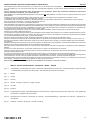 5
5
-
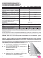 6
6
-
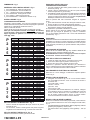 7
7
-
 8
8
-
 9
9
-
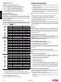 10
10
-
 11
11
-
 12
12
-
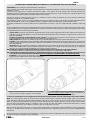 13
13
-
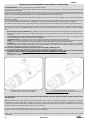 14
14
-
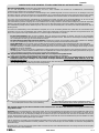 15
15
-
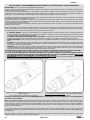 16
16
-
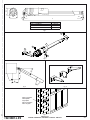 17
17
-
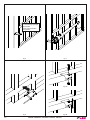 18
18
-
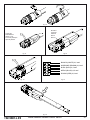 19
19
-
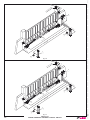 20
20
-
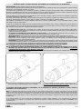 21
21
-
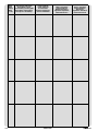 22
22
-
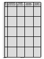 23
23
-
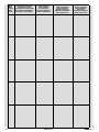 24
24
-
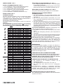 25
25
-
 26
26
-
 27
27
-
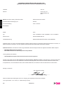 28
28
-
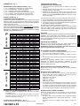 29
29
-
 30
30
-
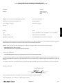 31
31
-
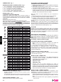 32
32
-
 33
33
-
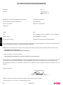 34
34
-
 35
35
-
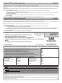 36
36


Tau P250BENC Use and Maintenance Manual
- Tipo
- Use and Maintenance Manual
in altre lingue
- English: Tau P250BENC
- français: Tau P250BENC
- español: Tau P250BENC
- Deutsch: Tau P250BENC
Documenti correlati
-
Tau ZIP Manuale del proprietario
-
-
-
-
-
-
-
-
-
 TAUBENREUTHER R16BENC Manuale del proprietario
