
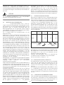
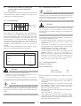
ENERGY & LIGHTING
TRAVELLER
T2500 H/HG-LP, T4000 H/HG-LP,
T5500 H/HG-LP
Generator
Installation and Operating Manual . . . . . . 1
Generatore
Istruzioni di montaggio e d’uso . . . . . . . .10
Generator
Montage- und Bedienungsanleitung . . .19
Generator
Montagehandleiding en
gebruiksaanwijzing. . . . . . . . . . . . . . . . . 28
Générateur
Instructions de montage
et de service . . . . . . . . . . . . . . . . . . . . . . 37
Generador
Instrucciones de montaje y de uso . . . . 48
EN
IT
DE
NL
FR
ES
title_dometic_16s_A4.fm Seite 1 Dienstag, 21. Februar 2017 2:50 14

L
N
I
O
M
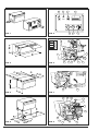
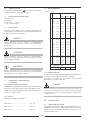
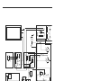
FIG. 1
FIG. 2
FIG. 3
FIG. 4
FIG. 5
FIG. 6
FIG. 7
FIG. 8
3 0
2 8
230 V
230 V
12 V
START
I
0
2 2
2 3
6
2 4
2 5
2 6
2 7
X
Y
Z
1 7
1 8
1 7
1 8
1 4
7
1 0
1 1 1 6
1 6
1 5
1 5
1 2
1 3
A
B
C
F
G
D
E
H
P
Q
1
1 9 2 0
2 1
5
3 6
4
3
2
8
9

1
©
All rights reserved
Printed in Italy
Text and graphics by: VEGA - Forlì
No part of this publication may be reproduced, copied or transmitted in any form or by any means without prior written permission from
DOMETIC ITALY srl.
Figures, descriptions, reference and technical data in this manual are given as mere example and are not binding.
Because of policy of continual product and safety improvement, we reserve the right to make changes at any time
without notice.
DOMETIC ITALY srl
GENERAL INDEX
................................................ Pag. 1÷9
................................................ Pag. 10÷18
................................................ Pag. 19÷27
................................................ Pag. 28÷36
................................................ Pag. 37÷45
................................................ Pag. 46÷54
I
D
NL
INDEX
Description Page
1.0 Identication .................................................. 2
1.1 Manufacturer ..................................................... 2
1.2 Definitions .......................................................... 2
1.3 Transport - Handling - storage ........................... 2
1.3.1 Storage conditions ............................................. 2
1.3.2 Weight ............................................................... 2
1.3.3 Overall dimensions ............................................. 2
1.3.4 Handling ............................................................ 2
2.0 Installation ...................................................... 2
2.1 Authorised personnel ......................................... 2
2.2 Mounting the generator ...................................... 3
2.3 Electrical connections ........................................ 3
2.3.1 Connection of the battery recharger ................... 3
2.3.2 Connection of the starter battery ........................ 3
2.3.3 Connection of the remote control panel ............. 3
2.4 Installing the fuel tank ......................................... 3
Connection to gas canister ................................ 3
3.0 General operation ......................................... 4
3.1 Description of generator and functioning ............ 4
3.2 Safety advice ..................................................... 4
3.3 Noise levels ........................................................ 4
4.0 Instructions for use ...................................... 5
4.1 Starting the generator ........................................ 5
4.2 Stopping the generator ...................................... 5
4.3 Inherent risks ..................................................... 5
4.4 Improper use ..................................................... 5
4.5 Useful advices.................................................... 5
4.6 Troubleshooting ................................................. 5
5.0 Maintenance operations .............................. 6
5.1 Nature and frequency of checks ........................ 6
5.2 Maintenance operations which do not
require qualified technicians ............................... 6
5.3 Maintenance operations which require
qualified technicians ........................................... 6
5.3.1 Oil change ......................................................... 7
5.3.2 Air filter maintenance .......................................... 7
5.3.3 Spark plug maintenance .................................... 7
5.3.4 Regulating the voltage........................................ 8
6.0 Inactivity and dismantling ........................... 8
6. Dismantling ......................................................... 8
7.0 Dealing with re hazards ............................. 8
8.0 Technical data sheet .................................... 9
8. Technical specifications ...................................... 9
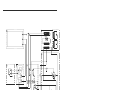
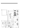
8.2 Wiring diagrams ......................................... 55÷69
GB
F
SP
Dometic Italy srl

2
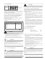
1.0 IDENTIFICATION
The identification plate of the machine is affixed outside
the plate casing (see fig. 1).
1.1 MANUFACTURER
DOMETIC ITALY srl
Via Virgilio, 3
47122 FORLI' - ITALY
P. IVA 00718330400
1.2 DEFINITIONS
In this handbook, three types of “safety graphics” are used
to point out different levels of danger or any other important
information:
DANGER
Draws attention to potentially dangerous situations which
may cause serious personal injury.
CAUTION
Draws attention to potentially dangerous situations which
may cause personal injury or material damage.
IMPORTANT
Draws attention to situations which may cause
malfunctioning or damage to the machine.
1.3 TRANSPORT - HANDLING - STORAGE
1.3.1 STORAGE CONDITIONS
The generator is protected against sudden impact by
suitable packing consisting of cardboard, polystyrene and
a wooden frame support.
The generator should be stored horizontally in a dry and
well-ventilated room.
1.3.2 WEIGHT
Gross weight (including packing):
Mod. 2500 .......................................... Kg 62
Mod. 4000 .......................................... Kg 114
Mod. 5500 .......................................... Kg 140
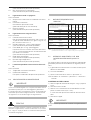
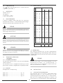
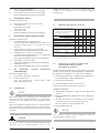
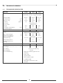
1.3.3 OVERALL DIMENSIONS
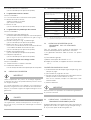
See figg. 2, 3, 4 :
Model
2500 4000 5500
A mm 470 660 700
B mm 535 740 --
C mm 565 770 --
D mm 320 475 515
E mm 315 355 510
F mm 260 310 --
G mm 27 62 --
H mm -- -- --
I mm 65 78 --
L mm 65 265 --
M mm 225 130 --
N mm 36 17 --
O mm 535 740 735
P mm 27 62 55
Q mm 260 310 370
X mm 590 780 770
Y mm 385 540 505
Z mm 335 380 550
Air intake area
cm
2
220 260
1.3.4 HANDLING
The packed generator can be handled by normal means of
lifting and transport.
Boxes are fitted with spacers which enable the use of
manual fork-lifts.
DANGER
Strictly observe the accident prevention precautions and
safety regulations during lifting and transport, and always
use machines
with a higher maximum capacity than the load to
be lifted.
2.0 INSTALLATION
2.1 AUTHORISED PERSONNEL
The generator shall be installed onto the vehicle (caravan,
motorhome or special vehicle) by authorised personnel
only, namely by skilled technicians or workshops, authorised
directly by DOMETIC ITALY srl
If the installation is carried out by non-authorized technicians
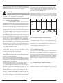
NOITALLATSNI "A" EPYTNOITALLATSNI "B" EPYT
.MID GNINEPO

3
DANGER
The instructions given in sections 2.2 2.3 2.4 are
addressed to qualified technicians only.
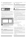
2.2 MOUNTING THE GENERATOR
Generators mod. 2500 - 4000 are provided
with fixing brackets,vibration dampers and petrol filter to be
placed on the fuel feed hose to the generator. Brackets
allow either suspended type "A” mounting (see fig. 3) or
traditional type "B” mounting (see fig. 4).
This is made possible by the supporting frame of the outer
casing.
Generator mod. 5500 is provided with brackets for fixing
the external seal, brackets for anchoring the unit, vibration
dampers, silencer (pos. 29 fig. 16) to be coupled to the
exhaust hose delivered as accessory AG 125 (pos. 34 fig.
16), and fuel filter which is standard installed inside the
casing (pos. 33 fig. 15). The brackets (pos. 31 fig. 16) which
allow to fix the seal (pos. 35 fig. 16) allow to mount the
generator complete with seal inside the arranged
compartment and to perfectly seal the vehicle side. The
exhaust hose can be positioned at will as shown in fig. 16
by rotating the curve inwards to either upper position or
lower position. By removing the curve, it is also possible to
directly fit the exhaust pipe by crossing the casing on its left-
hand side. The prearranged floor must tolerate both the
generator mass and the vibrations due to the motion of the
vehicle ("TYPE B” mounting).
The
type “A” mounting (suspended installation) offers the
following advantages: reduced overall dimensions, quick
installation, easy access for both ordinary and extraordinary
maintenance operations.
Make sure there is enough space around the generator
casing for air to pass freely (for cooling). It is also necessary
to leave at least 20 mm distance between the casing and the
surrounding parts.
If the breathing manifold is positioned behind one of the
vehicle's wheels, make sure that the tyre is prevented from
throwing water into the casing when travelling on wet roads.
For the type “A” mounting, use the plate supports provided
to ensure that the genset is fixed securely. If type “B”
mounting is preferred (traditional installation), a watertight
compartment (fig. 2), set towards the vehicle interior and
having the dimensions given in section 1.3.3, needs to be
prearranged, with exhaust holes and air inlets drilled into the
floor and door. In addition, use an exhaust union (fig. 4),
supplied as accessory, to be fixed directly onto the generator
casing with screws or rivets. In order to prevent the exhaust
gas recycling within the compartment, place flameproof
sealing around the exhaust union.
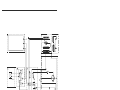
2.3 ELECTRICAL CONNECTIONS
For the 230V use a standard cable with cross-section
according to table 1 below. Pass it inside the casing via the
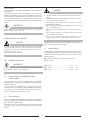
airlead (pos. 30 fig. 7 and 9) and connect to the terminals
(pos. 17/18 fig. 6 and 14). Connect the earth wire to pos. 15.
The electrical circuit should have a relay or change-over
switch (such as accessory AG102/AG113), so as to prevent
any damage to the generator when the camper is connected
to an external mains supply (precedence is automatically
given to the mains).
2.3.1 CONNECTION OF BATTERY
RECHARGER
Use a wire with minimum cross-section according to table
1 above to connect the terminal (pos. 16 fig. 6 and 14) to
the positive lead of the battery to be recharged.
Insert the AG111 voltage regulator, or alternatively a switch,
to interrupt recharging when complete.
(See wiring diagrams, pages 55 ÷ 71).
2.3.2 CONNECTION OF STARTER BATTERY
For starting the generator, connect the positive terminal of
the vehicle's starter battery to pos. 12 fig. 6 and 14 using a
flame-resistant sheathed cable having a cross-section
according to table 1 above.
The earth cable should have the same cross-section and be
connected from pos. 13 to the vehicle chassis. Make sure
that a clean, rust-free contact is made (i.e. rub down surface
if painted), and protect with grease.
2.3.3 CONNECTION OF REMOTE CONTROL
PANEL
Fix the control panel in desired position inside the vehicle
and use the individually-tested AG103 extension cable to
connect it to the genset by means of the connector pos. 14
fig. 6 and 14.
2.4 INSTALLING THE FUEL TANK
Install the fuel tank as near as possible to the generator and
if possible on the same horizontal level, or up to 30cm
below. As well as reducing the length of fuel pipe as much
as possible, make sure it is not bent or squashed. Do not
put the tank near sources of heat, and make sure that water
Mod.
Cross-section Cross-section
6 m > 6 m
mm
2
-230 V mm
2
-12 V
2500 2.5 2.5 10 16
4000 4 2.5 10 16
5500 4 2.5 16 25
TAB. 1
Power cables
Battery connection
Battery recharger
or workshops, Dometic Italy srl disclaims any responsibility
for the safety and efficient running of the generatore
accordind to the M.D. 89/392/EEC

4
cannot infiltrate.
Use LOCTITE 577 to make all connections, so as to prevent
fuel leakages.
To connect the fuel tank to the generator, use a 6x13mm
rubber-coated tube, of the same type used for the genset
and suitable for unleaded petrol. For the extension, use the
ties and filter provided. It is advisable to use fuel hose
AG118 (accessory) for the connection from tank to refuelling-
mouth.
IMPORTANT
Model 5500 does not need fuel tank, since it is standard
fitted inside the genset casing.
CONNECTION TO GAS CANISTER
CAUTION
For the LPG genset, withdraw the gas from the upright
canister and the vehicle's service regulator and from the
upper part, so that gas enters the genset at low pressure
and in the gaseous state.
(Working pressure: 30 mbar)
3.0 GENERAL OPERATION
IMPORTANT
The firm disclaims any responsability for damages arising
from malfunctioning of the generator.
3.1 DESCRIPTION OF GENERATOR AND
FUNCTIONING
The generator consists of an endothermic petrol engine
connected to an alternator which produces both alternate
and direct current.
The unit comes in a soundproof casing made of pressed
steel plate and insulated with special deadening materials.
Fuel comes to the combustion engine through a pump
which is standard fitted on the unit itself.
3.2 SAFETY ADVICE
The unit is housed within a perfectly closed casing. Therefore,
there is no danger of accidental contacts with hot or moving
parts or wires under voltage.
The door of the unit is fitted with lock and key and should
not be left within the reach of children or non-authorised
persons.
DANGER
• The unit shall be used only and exclusively with the door
closed.
• Keep inflammable substances like petrol, paints, solvents,
etc. away from the generator.
• Do not let hot parts of the genset come into contact with
inflammable materials.
• Do not fill up with the engine running if the tank is placed
close to the generator.
• Do not touch the generator or its connections with wet
hands.
• Do not replace the fuses or thermal switches with new
ones of higher amperage.
• Any check of the electrical parts shall be made with
engine stopped and by authorised technicians only.
The generator is manufactured according to the safety rules
given in the Conformity Declaration.
3.3 NOISE LEVELS
The generator has been submitted to a noise emission test
at a qualified ISTEDIL lab, where all the necessary tests were
carried out and EC Certificate No.I-225/92 issued, stating
following results:
Measured according to: EC DIRECTIVE 84/536
NOISE LEVEL:
Mod. 2500 .......................................... LwA 85
Mod. 4000 .......................................... LwA 87
Mod. 5500 .......................................... LwA 87

5
4.0 INSTRUCTIONS FOR USE
4.1 STARTING THE GENERATOR
Normally the vehicle's 12V battery is used to start the
genset.
First press the red button (pos. 27 fig. 5) on the control panel
into the “I” position.
To start the genset from cold, press and hold down the
green START button (pos. 25 fig. 5) together with the white
CHOKE button (pos. 26 fig. 5) for max. 5 seconds.
CAUTION
Do not make prolonged or repeated (more than 5 consecu-
tive) attempts to start the genset, as this may damage the
starter motor.
To start the genset when already warmed-up, or during the
summer, when the outside temperature is high, press the
green “START” button (pos. 25 fig. 5) only.
In an emergency the genset can be started manually using
the pull-cord handle (pos. 4 fig. 8 and 15) and holding the
choke magnet (pos. 36 fig. 8 and 15) shut with one hand
if the engine is cold.
The green LED on the control panel ((pos. 23 fig. 5) indicates
that the genset is running correctly.
4.2 STOPPING THE GENERATOR
Push the red “STOP” button (pos. 27 fig. 5) on control panel
into the ”0" position. Alternatively use the safety switch on
the genset itself (pos. 7 fig. and 14) for models 2500 - 4000
- 5500.
4.3 INHERENT RISKS
DANGER
The generator is fitted with a combustion engine, and
therefore runs on highly inflammable fuelstuffs.
Exhaust gases are conveyed under the casing and, although
mixed with cooling air, they are inevitably hot.
Do not touch the parts of the casing close to the exhaust
and do not place your hands or other objects within the
duct.
4.4 IMPROPER USE
DANGER
The generator is to be installed by qualified technicians only,
according to the manufacturer’s instructions.
The generator is to be used only and exclusively for producing
current for mobile vehicles, fitted with a standard electrical
circuit in keeping with the power supplied by the generator.
4.5 USEFUL ADVICES
To use the genset at best, we remember you that little, but
prolonged, overloads may cut off thermal switches pos. 10
and 11 shown in fig. 6 and 14.
During running-in, it is advisable that the new engine is not
subjected to loads exceeding its nominal load by 70%, at
least during the first 50 running hours.
4.6 TROUBLESHOOTING
We have listed below some problems which may occur,
along with their respective causes and possible solutions.
In the case of problems which are not listed below, please
seek advice from an authorised after-sales service centre.
1 When the green “START” button (pos. 25 fig. 5)
on the control board is pressed, the generator
does not work.
Causes and Solutions:
1.1 Check that the red switch (pos. 27 fig. 5) is in the “I”
position.
1.2 Electrical wires loose or disconnected.
(Have checked by qualified personnel).
1.3 No power supplied to starter-motor.
(Have checked by qualified personnel).
1.4 Earth wire of generator disconnected.
(Have checked by qualified personnel).
2 The starter-motor turns, but the generator does
not start.
Causes and Solutions:
2.1 No fuel: check.
2.2 No oil in engine.
Check if the red warning light (pos. 6 fig. 5) on the
control board blinks during the starting phase.
Check the oil level and top up if necessary (see
Maintenance section).
2.3 The safety switch (pos. 7 fig. 6 and 14) is in the "0"
position.
Check and press in the “I” position.
2.4 Check that the engine's spark-plug nipple is fully
inserted.
2.5 No current to the spark plug.
(Have checked by qualified personnel).
2.6 No fuel getting to the carburettor.
(Have checked by qualified personnel).

6
3 The generator tends to stall.
Causes and Solutions:
3.1 No more fuel left in the tank: refill.
3.2 Low oil level.
Check and top up.
(See Maintenance section).
3.3 Air filter is dirty.
(Have checked by qualified personnel).
4 The generator does not produce current
Causes and Solutions:
4.1 Thermal switch off.
Set it to 'on' by pushing the switches (pos. 10 fig. 6
and 14) for 230V A.C., (pos. 11 fig. 6 and 14)
for 12V
D.C.
4.2 Condenser (pos. 19 fig. 8) damaged.
(Have checked by qualified personnel).
4.3 Diode rectifier (pos. 21 fig. 8) damaged.
In this case, only the 12V D.C. and the green LED on
the control board are not working.
(Have checked by qualified personnel).
4.4 Rotor diodes damaged.
(Have checked by qualified personnel).
4.5 Frequency too low.
(Have checked by qualified personnel).
5 The unloaded current produced oscillates.
Causes and Solutions:
5.1 Too much oil in the engine: check.
5.2 Defective carburation.
Have the carburettor cleaned by qualified personnel.
5.0 MAINTENANCE OPERATIONS
IMPORTANT
Use only genuine spare parts. The generator may get
damaged if other than genuine parts having a different
quality standard are used.
To make sure that the generator keeps working to maximum
efficiency, it is essential that it is properly and regularly
maintained. Additionally, a proper maintenance grants the
generator a longer lifetime.
DANGER
Before carrying out any check or maintenance operation on
the genset, rotate safety switch (pos. 7 fig. 6 and 14) to "0"
position to prevent any accidental startings of the unit.
5.1 NATURE AND FREQUENCY OF CHECKS
5.2 MAINTENANCE OPERATIONS WHICH
DO NOT REQUIRE QUALIFIED
TECHNICIANS
To carry out these operations, the generator door first
needs to be opened. Therefore, the following measures
should be taken:
1) The generator must be stopped with all parts cold.
2) Let the unit cool.
3) Set the safety switch to the “0” position.
N.B.Remember to set it to the “I” position again after
check!
OIL LEVEL CHECK
1) Remove the oil filling cap (pos. 9 fig. 8) and clean the
dipstick.
2) Reintroduce the dipstick by screwing it in fully.
3) Remove the dipstick and check that the oil level is
between min. and max. levels.
If not, top up with the recommended oil.
4) Refit the cap.
IMPORTANT
All checks should be carried out with the genset horizontal.
5.3 MAINTENANCE OPERATIONS WHICH
REQUIRE QUALIFIED TECHNICIANS
For some maintenance operations you need to slide the unit
out on its runners (pos. 28 fig. 7 and 15) after first loosening
the fixing screws.
Inspection
▲
Change
▲
(2)
▲
(2)
Air filter Clean
ing
(1) ▲(2)
Spark plug
Inspection-Cleaning
▲
(2)
Valve adjustment Check - adjust ▲
(2)
Fuel filter and tank
Cleaning ▲
(2)
R.p.m.
or frequen
cy Adjust ▲
(2)
▲
(2)
Suspension points for
vibration dampers I
nspection ▲
(2)
Fuel hoses Check (replace,
Every two years
(2)
if necessary)
REMARK (1):Clean more frequently when used in dusty areas
(2): Get this work done by a specialist only
ORDINARY MAINTENANCE INTERVAL
carry out at the intervals or after the running
hours given in the table, depending on which
occurs first.
Every
year
or
300 hours
Every
6 months
or
100 hours
First
month
or
20 hours
Every
3 months
or
50 hours
Every
use
Engine oil

7
5.3.1 OIL CHANGE
Use detergent oil for fourstroke engines, class API SG or SF
(indicated on the oil can) with SAE viscosity suitable for the
climate (see table).
To allow the oil to drain out easier, run the engine for about
3÷5 minutes. Then discharge the oil when the engine is still
warm so that the emptying is quicker and more complete via
the drainage hose (pos. 2 fig. 8 and 15) by removing the
drain cap (pos. 8 fig. 8 and 15).
Top up with oil of the recommended type via the filling cap
(pos. 9 fig. 8).
Table 2 shows the amount of oil in the oil pan.
Mod. Liters
2500 0.6
4000 1.1
5500 1.1
T
AB. 2
DANGER
• Warm oil may burn you.
• Running the engine with a poor amount of oil can
seriously damage the engine itself.
• Check the oil level when engine is stopped.
IMPORTANT
Used oils must never be poured on the ground. They shall
be collected and consigned to qualified companies for the
disposal in accordance with any local regulations.
5.3.2 AIR FILTER MAINTENANCE
IMPORTANT
A dirty air filter reduces the air flow to the carburettor. To
keep the carburettor working properly, check it often. Check
more frequently if the engine is used in dusty areas.
DANGER
Never use diesel oil or solvents with a low evaporation point
for cleaning the air filter, since this may lead to danger of
flames or explosion.
Never let the engine run without the air filter. It would get
damaged in a short space of time.
1. Carefully check both cartridges. Replace them if there
are holes or tears
2. Sponge cartridge: wash it with a neutral detergent
s
olution and rinse carefully. Let the cartridge dry
completely, then soak it in clean engine oil and wring out
the excess.
3. Paper cartridge: smoothly beat it several times on a hard
surface to remove any dirt, or blow compressed air
through the filter from inside to out. Do not brush the dirt:
this operation would just push it into the fibres. If the
paper cartridge is too dirty, replace it.
5.3.3 SPARK PLUG MAINTENANCE
RECOMMENDED SPARK PLUG:
Mod. 2500/4000/5500
BP6ES, BPR6ES NGK
W20EPU, W20EPRU ND
Never use a spark plug with a different thermal degree.
1. Remove the spark plug nipple (pos. 1 fig. 8) and use a
suitable wrench to remove the spark plug.
2. Visually check the spark plug. If it is worn or if the
insulator is broken or chipped, replace it. Clean the
spark plug with an iron brush if it is to be used again.
3. Measure the electrode distance by means of a thickness
gauge.
The distance should be 0.70.8 mm.
Adjust, if necessary, by bending the side electrode.
4. Check that the spark plug washer is in good condition
and screw it manually to prevent it being set at an angle.
5. Once mounted, tighten the spark plug using a wrench
with the right driving torque.
-30° -20° -10 ° 0 10 ° 20° 30° 40°
Room Temperature
MULTIGRADE
SG / SF
Hot climates
Cold climates
10W 30
15W 50

8
IMPORTANT
When mounting a new spark plug, tighten it a half-turn after
it has compressed the washer. When re-using the same
spark plug, tighten it 1/8-1/4 turn after the washer
compression.
CAUTION
The spark plug should be tightened carefully. A loose spark
plug can get very hot and damage the engine.
5.3.4 REGULATING THE VOLTAGE
This regulation should be carried out with the engine warm
and the generator running without a load.
Check the generator voltage using a tester or voltmeter
connected to the vehicle's 230V socket or to the terminals
(pos. 17-18 fig. 6 and 14) of the generator terminal board.
The voltage should be between 230 and 240 Volts.
If these values are not obtained, adjust the current regulation
screw (pos. 32 fig. 10 and 15) until they are.
Rotate clockwise to increase the voltage.
Rotate anticlockwise to decrease both r.p.m. und voltage.
6.00 INACTIVITY AND DISMANTLING
6.01 DISMANTLING
If the unit must be dismantled, get the work done by
authorised workshops.
7.0 DEALING WITH FIRE HAZARDS
In case of fire, do not open the generator casing and use
type-approved fire-extinguishers.

9
8.0 TECHNICAL DATA
8.1 TECHNICAL SPECIFICATIONS
ENGINE 2500H 4000H 5500H
Type
S
inglecylinder, f
ourstroke,
overhead valves
Honda m
odel GX 160 GX 270 GX 390
Displacement cm
3
163 270 389
Stroke x b
ore mm 68x45 77x58 88x64
Consumption g
kW/h 230 230 235
Fuel Leadfree p
etrol
Starter system Electronic
S
park plug NGK NGK NGK
E
ngin
eoil sump capacity litre 0.6 1.1 1.1
Frequency r e g o l a t o r Automatic w
ith centrifugal masses
Ty
pe
Peak m
ax. power W 2200 3800 5300
For c
ontinuous utilization W 2000 3500 4500
Voltage/frequence 2
30V 50Hz
D.C. p
ower 12V 10A 12V 10A 12V 10A
Rotor i
nsulation class H H H H
Stator i
nsulation class F F F F
Cooling Centrifugal f
an
GENERATOR 2500H 4000H 5500H
Total w
eight Kg 50 102 132
Overall d
imensions (LxWxH) mm
530x385x290 660x475x355 700x520x510
Ignition Electric/man.
Fuel p
ump Vacuum
Remote c
ontrol Separate control board with:
pushbutton s
tarter
pushbutton c
hoke
stop s
witch
low f
uel LED
running L
ED
low o
il LED (automatic stop)
hour m
eter
ALTERNATOR 2500H 4000H 5500H
Synchronous, singlephase, selfregulated,
selfenergized, twopole, brushless

10
INDICE
Descrizione Pagina
1.0 Identificazione .................................................. 11
1.1 Costruttore ...................................................... 11
1.2 Definizioni ........................................................ 11
1.3 Trasporto - Movimentazione
Immagazzinamento .......................................... 11
1.3.1 Condizioni di immagazzinamento ..................... 11
1.3.2 Peso ................................................................ 11
1.3.3 Dimensioni d'ingombro .................................... 11
1.3.4 Movimentazione ............................................... 11
2.0 Installazione ................................................. 11
2.1 Personale autorizzato ....................................... 11
2.2 Istruzioni per il fissaggio del generatore ............ 12
2.3 Istruzioni per il collegamento elettrico ............... 12
2.3.1 Collegamento elettrico del carica batterie ......... 12
2.3.2 Collegamento batteria ...................................... 12
2.3.3 Collegamento cruscotto comando a distanza .. 12
2.4 Istruzioni per l'installazione serbatoio
carburante ....................................................... 13
3.0 Indicazioni e funzionamento ..................... 13
3.1 Descrizione del generatore e funzionamento .... 13
3.2 Sicurezza delle macchine ................................. 13
3.3 Indicazione sul rumore ..................................... 13
4.0 Uso del generatore ..................................... 14
4.1 Avviamento del generatore............................... 14
4.2 Arresto del generatore ..................................... 14
4.3 Informazione sui pericoli ineliminabili................. 14
4.4 Informazione sugli usi non consentiti ................ 14
4.5 Consigli utili ...................................................... 14
4.6 Indicazioni per l'individuazione dei guasti.......... 14
5.0 Indicazioni per la manutenzione .............. 15
5.1 Natura e frequenza delle verifiche ..................... 15
5.2 Interventi manutentivi che non richiedono
personale qualificato ........................................ 15
5.3 Interventi manutentivi che richiedono
personale qualificato ........................................ 16
5.3.1 Sostituzione olio ............................................... 16
5.3.2 Manutenzione filtro aria .................................... 16
5.3.3 Manutenzione candela ..................................... 16
5.3.4 Regolazione della tensione ............................... 17
6.0 Indicazioni per la messa fuori servizio .... 17
6.1 Smantellamento ............................................... 17
7.0 Mezzi antincendio da utilizzare ................ 17
8.0 Dati tecnici ................................................... 18
8.1 Caratteristiche tecniche.................................... 18
8.2 Schemi elettrici .......................................... 55÷69
© Dometic Italy
srl
Tutti i diritti riservati
Stampato in Italia
Realizzazione: VEGA - Forlì
INDICE GENERALE
................................................ Pag. 1÷9
................................................ Pag. 10÷18
................................................ Pag. 19÷27
................................................ Pag. 28÷36
................................................ Pag. 37÷45
................................................ Pag. 46÷54
I
D
NL
F
SP
GB
Nessuna parte di questo manuale può essere riprodotta, copiata o divulgata con qualsiasi mezzo senza l’autorizzazione scritta della
Dometic Italy
srl.
Le figure, le descrizioni, i riferimenti ed i dati tecnici contenuti nel presente manuale sono indicativi e non impegnativi.
La Dometic Italy
srl si riserva il diritto di apportare in qualsiasi momento e senza preavviso tutte le modifiche che riterrà opportuno, nella
costante ricerca di migliorare la qualità e la sicurezza, senza impegnarsi ad aggiungere di volta in volta questo manuale.

11
1.3.3 DIMENSIONI D'INGOMBRO
Vedere figg. 2, 3, 4 :
1.3.4 MOVIMENTAZIONE
Il generatore completo di imballo è movimentabile con i
comuni mezzi di sollevamento e trasporto.
Le casse sono dotate di distanziali per l’utilizzo di transpallet.
PERICOLO
Durante le fasi di sollevamento e trasporto rispettare le
norme antinfortunistiche e di sicurezza ed utilizzare
macchine con portata massima superiore al carico da
sollevare.
2.0 INSTALLAZIONE
2.1 PERSONALE AUTORIZZATO
Il generatore deve essere installato sul mezzo (camper,
motor home o veicoli speciali) solo ed esclusivamente da
ditte o personale qualificato ed autorizzato da:
DOMETIC ITALY srl.
Qualora l’installazione sia effettuata da personale o da ditte
1.0 IDENTIFICAZIONE
La targhetta di identificazione della macchina è fissata
all'esterno della cassa in lamiera (vedi fig. 1).
1.1 COSTRUTTORE
Dometic Italy srl
Via Virgilio, 3
47122 FORLI' - ITALY
P. IVA 00718330400
1.2 DEFINIZIONI
In questo libretto sono utilizzati tre "simboli grafici di sicurez-
za", che hanno lo scopo di evidenziare altrettanti livelli di
pericolo o importanti informazioni:
PERICOLO
Richiamo che indica una situazione potenzialmente perico-
losa che, potrebbe provocare infortuni gravi.
ATTENZIONE
Richiamo che indica una situazione potenzialmente perico-
losa che potrebbe provocare infortuni o danni a cose.
IMPORTANTE
Richiamo che indica una situazione potenzialmente perico-
losa che potrebbe provocare mal funzionamenti o danni alla
macchina.
1.3 TRASPORTO - MOVIMENTAZIONE -
IMMAGAZZINAMENTO
1.3.1 CONDIZIONI DI IMMAGAZZINAMENTO
Il generatore viene protetto contro gli urti da un opportuno
imballaggio di cartone, polistirolo e base di appoggio in
legno.
Il generatore deve essere immagazzinato in posizione nor-
male in ambiente coperto, asciutto e ventilato.
1.3.2 PESO
Peso lordo completo di imballaggio:
Mod. 250
0 .......................................... Kg 62
Mod. 4000 .......................................... Kg 114
Mod. 5500 .......................................... Kg 140
Modello
2500 4000 5500
A mm 470 660 700
B mm 535 740 --
C mm 565 770 --
D mm 320 475 515
E mm 315 355 510
F mm 260 310 --
G mm 27 62 --
H mm -- -- --
I mm 65 78 --
L mm 65 265 --
M mm 225 130 --
N mm 36 17 --
O mm 535 740 735
P mm 27 62 55
Q mm 260 310 370
X mm 590 780 770
Y mm 385 540 505
Z mm 335 380 550
Area feritoie sportello
cm
2
220 260
INSTALLAZIONE TIPO “B” INSTALLAZIONE TIPO “A”
DIM. VANO

12
del generatore. Per evitare il riciclo dei gas di scarico dentro
il vano è necessario inserire una guarnizione di tenuta
ignifuga, attorno al raccordo di scarico.
2.3 ISTRUZIONI PER IL COLLEGAMENTO
ELETTRICO
Usare per la 230V un cavo a norme la cui sezione è da
rilevare in tab. 1; inserirlo nella cassa tramite il passacavo
(pos. 30 fig.7 e 9 ) e collegarlo ai morsetti (pos.17/18 fig.6
e 14). In pos.15 fissare il cavo di terra.
Occorre installare sull’impianto elettrico del mezzo un relè o
commutatore (es. l'accessorio AG102/AG113) per non
danneggiare il generatore quando è allacciato alla rete
d'alimentazione esterna: bisogna dare la precedenza alla
rete esterna.
2.3.1 COLLEGAMENTO ELETTRICO DEL CA-
RICA BATTERIE
Usare un cavo la cui sezione è da rilevare in tab. 1,
collegandolo al morsetto (pos.16 fig.6 e 14) e al polo
positivo della batteria che si vuole caricare.
E' consigliabile inserire il regolatore di tensione AG 111 o un
interruttore per interrompere la carica sulla batteria.
(Vedere schemi elettrici a pag. 55 ÷ 71)
2.3.2 COLLEGAMENTO BATTERIA
Per l’avviamento del generatore collegarsi al polo positivo
della batteria di avviamento del mezzo con un cavo a norme
inguainato la cui sezione è da rilevare in tab. 1 e collegarlo
in pos.12 fig.6 e 14.
Il cavo di massa deve avere la stessa sezione e va collegato
in pos.13 e al telaio del mezzo. Occorre assicurarsi che il
contatto sia buono, asportando se necessario la vernice o
la ruggine dalla superficie, proteggendo il collegamento con
grasso.
2.3.3 COLLEGAMENTO CRUSCOTTO CO-
MANDO A DISTANZA
Scegliere la posizione desiderata all'interno del mezzo e
usufruire della prolunga AG 103 per il collegamento del
cruscotto al generatore tramite il connettore pos. 14 fig. 6
e 14.
non autorizzate, Dometic Italy srl declina ogni responsabilità
sul buon funzionamento e sulla sicurezza in base alla:
D.M. 89/392/CEE.
PERICOLO
Le indicazioni riportate ai punti 2.2 2.3 2.4 sono ad uso
esclusivo degli installatori specializzati.
2.2 ISTRUZIONI PER IL FISSAGGIO DEL GE-
NERATORE
I generatori mod. 2500 - 4000 sono forniti con
la dotazione di staffe per l'ancoraggio del gruppo con
antivibranti supplementari e filtro benzina da interporre
lungo il tubo di aduzione carburante al generatore. Le staffe
permettono il montaggio sia in sospensione: montaggio di
“TIPO A” (vedi fig. 3), sia in modo tradizionale: montaggio di
“TIPO B” (vedi fig. 4).
Ciò è possibile grazie alla struttura portante dell’involucro
esterno.
Il generatore mod. 5500 è fornito di serie con la dotazione
di staffe per il fissaggio della guarnizione di finitura, staffe per
l'ancoraggio del gruppo con antivibranti supplementari,
silenziatore (pos. 29 fig. 16) da montare in linea al tubo di
scarico fornito come accessorio AG 125 (pos. 34 fig. 16) e
filtro benzina montato di serie all'interno della cassa (pos. 33
fig. 15). Le staffe (pos. 31 fig. 16) per il fissaggio della
guarnizione (pos. 35 fig. 16) permettono di montare il
generatore completo di guarnizione nel vano predisposto,
sigillando perfettamente sul fianco del mezzo. Il tubo di
scarico può essere indirizzato a scelta come indicato in fig.
16, ruotando la curva all'interno della macchina in posizione
superiore, inferiore oppure, togliendola, è possibile entrare
direttamente con il tubo di scarico attraversando la cassa
sul fianco sinistro. Il piano d'appoggio predisposto dovrà
sopportare, oltre al peso del generatore, anche le sollecita-
zioni del mezzo in movimento (montaggio di “TIPO B”).
Il montaggio di “TIPO A” (installazione esterna) offre i se-
guenti vantaggi: minor spazio di ingombro, rapida installa-
zione, facile accesso per le operazioni di normale e straor-
dinaria manutenzione.
Occorre assicurarsi che attorno al cofano del generatore vi
sia spazio sufficiente per il passaggio d’aria di raffredda-
mento; inoltre lasciare almeno 20 mm di spazio libero fra il
cofano e le parti circostanti.
Nel caso in cui la presa d’aria di aspirazione del generatore
resti dietro a una ruota del mezzo, occorre impedire che, in
caso di pioggia, la ruota del mezzo butti acqua dentro al
generatore.
Per il montaggio di “TIPO A” è necessario usufruire dei due
supporti di lamiera in dotazione per garantire un solido
fissaggio del gruppo.
Se si decide di adottare il montaggio di “TIPO B” (installazio-
ne interna) , occorre predisporre un vano a tenuta stagna
(fig. 2) verso l’interno del mezzo con dimensioni minime
indicate al punto 1.3.3, con i fori di scarico e prese d’aria
praticate sul pianale e sullo sportello. Occorre inoltre utiliz-
zare il raccordo di scarico (fig. 4), fornito come accessorio,
che sarà fissato, tramite viti o rivetti, direttamente sul cofano
Mod. Sez.
mm
2
Sez.
mm
2
6 m > 6 m
230 V 12 V
2500 2,5 2,5 10 16
4000 4 2,5 10 16
5500 4 2,5 16 25
TAB. 1
Cavi di potenza
Collegamento batteria
Carica batteria

13
2.4 ISTRUZIONI PER L’INSTALLAZIONE DEL
SERBATOIO
L’ubicazione del serbatoio deve essere scelta in modo da
ridurre al minimo la lunghezza del tubo carburante. Evitare
inoltre che la sezione del tubo possa essere ridotta per
strozzature, curvature o schiacciamenti. Si consiglia inoltre
di installare il serbatoio allo stesso livello del generatore o al
massimo 30 cm sotto. Non posizionare il serbatoio nelle
vicinanze di fonti di calore e al riparo da infiltrazioni esterne
di acqua.
Montare i raccordi con LOCTITE 577 per evitare il pericolo
di perdite di carburante.
Usare per il collegamento serbatoio-generatore un tubo di
gomma rivestito adatto a benzina verde delle dimensioni 6
x13 dello stesso tipo usato nel gruppo. Per la prolunga è
indispensabile usufruire delle fascette e del filtro in dotazio-
ne. Si consiglia di usare il tubo AG 118 (accessorio) per il
collegamento dal serbatoio al bocchettone.
IMPORTANTE
Il modello 5500 non necessita di serbatoio poichè è instal-
lato di serie all'interno della cassa.
COLLEGAMENTO DELLA BOMBOLA GAS GPL
ATTENZIONE
Il gruppo ad alimentazione GPL deve prelevare il gas della
bombola in posizione verticale e dalla parte superiore, dopo
il rubinetto e DOPO il regolatore della bombola, perchè
l'alimentazione avvenga allo stato gassoso e in bassa pres-
sione.
(Pressione di lavoro: 30 mbar)
3.0 INDICAZIONI E FUNZIONAMENTO
IMPORTANTE
La ditta non risponde dei danni dovuti al mancato funziona-
mento del generatore.
3.1 DESCRIZIONE DEL GENERATORE E
FUNZIONAMENTO
Il generatore di corrente è costituito da un motore
endotermico a benzina collegato ad un alternatore che
produce corrente elettrica alternata e continua.
Il gruppo è montato all’interno di un cofano in lamiera
d’acciaio stampato isolato ed insonorizzato con speciali
materiali fonoassorbenti.
L’alimentazione del carburante al motore endotermico av-
viene tramite una pompa montata di serie sul generatore.
3.2 SICUREZZA DELLE MACCHINE
Il gruppo è alloggiato nel cofano perfettamente chiuso
pertanto non esiste il rischio di contatto con parti mobili, con
temperature elevate, o con conduttori sottotensione.
Lo sportello è dotato inoltre di apertura con serratura a
chiave che non deve essere lasciata alla portata dei bambini
o di persone inesperte.
PERICOLO
• Il gruppo deve essere utilizzato solo ed esclusivamente
a sportello chiuso.
• Allontanare le sostanze infiammabili dal generatore quali
ad esempio: benzina, vernici, solventi, ecc.
• Assicurarsi che le parti calde del gruppo non siano in
contatto con materiali facilmente infiammabili.
• Non fare il pieno di benzina con il motore in moto se il
serbatoio è posto nelle vicinanze del generatore.
• Non toccare il generatore o i collegamenti con le mani
bagnate.
• Non sostituire i fusibili o termici con altri di amperaggio
maggiore.
• Eventuali controlli di parti elettriche vanno eseguiti a
motore spento, e solo da personale autorizzato.
Il generatore è realizzato secondo le norme di sicurezza
indicate nella dichiarazione di conformità.
3.3 INDICAZIONE SUL RUMORE
Il generatore è stato sottoposto ad esame di emissione
acustica presso il laboratorio qualificato ISTEDIL che ha
provveduto ad eseguire le prove rilasciando certificato CEE.
N° I-225/92 con i seguenti risultati:
Misurazioni DIRETTIVA CEE 84/536
LIVELLO DI POTENZA ACUSTICA:
Mod. 2500 .......................................... LwA 85
Mod. 4000 .......................................... LwA 87
Mod. 5500 .......................................... LwA 87

14
4.0 USO DEL GENERATORE
4.1 AVVIAMENTO DEL GENERATORE
L’avviamento del gruppo avviene normalmente tramite
batteria a 12 volt in dotazione al veicolo.
Prima di procedere all’avviamento del motore posizionare
l’interruttore rosso (pos. 27 fig. 5) in posizione "I".
Per l’avviamento a motore freddo premere e mantenere
premuto il pulsante verde d'avviamento (pos. 25 fig. 5)
insieme al pulsante bianco "aria" (pos. 26 fig. 5) per un
tempo
non superiore ai 5 secondi.
ATTENZIONE
Non insistere mai più di 5 tentativi consecutivi vi è il rischio
di danneggiare il motorino di avviamento.
Per l’avviamento a motore caldo o d’estate, quando la
temperatura ambiente è molto elevata premere solo il
pulsante verde “avviamento” (pos. 25 fig. 5).
In caso di emergenza si può avviare il gruppo manualmente
utilizzando l'impugnatura di avviamento (pos. 4 fig. 8 e 15);
se il motore è freddo bisogna agire anche sull'asta di
comando dell'elettromagnete (pos. 36 fig. 8 e 15) fino a
portare la leva dell'aria in posizione chiusa.
Il corretto funzionamento è evidenziato dalla spia verde
(pos. 23 fig. 5).
4.2 ARRESTO DEL GENERATORE
Premere in posizione "0" l’interruttore rosso “STOP” (pos.
27 fig. 5). In alternativa, solo per i modd. 2500 - 4000-5500
usare l'interuttore di sicurezza (pos. 7 fig. 6 e 14).
4.3 INFORMAZIONE SUI PERICOLI INELI-
MINABILI
PERICOLO
Il generatore è dotato di motore a scoppio, quindi il carbu-
rante utilizzato è altamente infiammabile.
Sotto al cofano vengono convogliati i gas di scarico che,
inevitabilmente, hanno temperature piuttosto elevate anche
se miscelati all’aria di raffreddamento.
Non toccare le zone del cofano vicine allo scarico e non
inserire le mani od oggetti vari nel cofano
4.4 INFORMAZIONE SUGLI USI NON CON-
SENTITI
PERICOLO
Il generatore deve essere installato solo ed esclusivamente
da personale qualificato ed autorizzato secondo le indica-
zioni fornite dal costruttore.
Il generatore deve essere impiegato ed utilizzato solo ed
esclusivamente per la produzione di corrente elettrica su
mezzi mobili dotati di impianto elettrico realizzato secondo
le normative ed in base alla potenza erogata dal generatore.
4.5 CONSIGLI UTILI
Per utilizzare al meglio il gruppo elettrogeno è bene tenere
presente che anche sovraccarichi di piccola entità, se
prolungati, provocano il disarmo dei termici di protezione
pos. 10 e 11 di fig. 6 e 14.
Nel periodo di rodaggio è importante non sottoporre il
motore nuovo ad un carico superiore al 70% del carico
nominale almeno per le prime 50 ore di funzionamento.
4.6 INDICAZIONE PER L'INDIVIDUAZIONE
DEI GUASTI
Vi elenchiamo gli inconvenienti che possono eventualmente
presentarsi; con relativa causa e possibili rimedi.
Per i guasti non previsti rivolgersi ad un centro assistenza
autorizzato o specializzato.
1 Premendo il pulsante verde “AVVIAMENTO”
(pos. 25 fig. 5) sul cruscotto non si riscontra
alcun funzionamento.
Cause e Rimedi:
1.1 Verificare che l’interruttore rosso (pos. 27 fig. 5) sia in
posizione "I".
1.2 Cavi elettrici interrotti.
(Fare controllare da personale qualificato).
1.3 Motorino di avviamento non alimentato.
(Fare controllare da personale qualificato).
1.4 Cavo di massa del generatore interrotto.
(Fare controllare da personale qualificato).
2 Il motorino di avviamento gira ma il generatore
non parte.
Cause e Rimedi:
2.1 Mancanza di carburante: controllare.
2.2 Mancanza olio nel motore.
Controllare se durante l’avviamento la spia rossa sul
cruscotto (pos. 6 fig. 5) lampeggia.
Verificarne il livello e ripristinarlo (vedi indicazioni per
la manutenzione).
2.3 Interruttore di sicurezza (pos. 7 fig. 6 e 14) in posizio-
ne "0".
Verificare e portare in posizione "I".
2.4 Controllare che il cappuccio della candela motore sia
inserito correttamente.
2.5 Non arriva corrente alla candela.

15
(Fare controllare da personale qualificato).
2.6 Non arriva benzina al carburatore.
(Fare controllare da personale qualificato).
3 Il generatore tende a spegnersi.
Cause e Rimedi:
3.1 Sta per finire il carburante nel serbatoio: fare riforni-
mento.
3.2 Livello olio insufficiente.
Controllare e ripristinare il livello.
(Vedi indicazioni per la manutenzione).
3.3 Filtro aria sporco.
(Fare controllare da personale qualificato).
4 Il generatore non eroga tensione.
Cause e Rimedi:
4.1 Protezione termica disinserita.
Reinserirla premendo gli interruttori (pos.10 fig. 6 e
14) per tensione alternata 230 V; (pos.11 fig. 6 e 14)
per tensione continua 12 V.
4.2 Condensatore (pos. 19 fig. 8) danneggiato.
(Fare controllare da personale qualificato).
4.3 Ponte diodi (pos. 21 fig. 8) danneggiato.
In questo caso non funziona solo la tensione conti-
nua 12 V ed è segnalato dal non funzionamento del
LED verde sul cruscotto.
(Fare controllare da personale qualificato).
4.4 Diodi rotore danneggiati.
(Fare controllare da personale qualificato).
4.5 Numero di giri troppo bassi.
(Fare controllare da personale qualificato).
5 La tensione prodotta senza carico inserito oscil
la.
Cause e Rimedi:
5.1 Troppo olio nel motore: controllare.
5.2 Carburazione difettosa.
Fare pulire il carburatore da personale qualificato.
5.0 INDICAZIONI PER LA MANUTENZIONE
IMPORTANTE
Usare solo ricambi originali. L'uso di parti di ricambio non di
equivalente qualità possono danneggiare il generatore.
Il controllo periodico e le regolazioni sono essenziali affinché
l'alto livello di prestazioni venga mantenuto. La manutenzio
ne regolare assicura inoltre lunga vita al generatore.
PERICOLO
Prima di eseguire qualsiasi controllo o intervento di manu
tenzione sul generatore, ruotare l'interruttore di sicurezza
(pos. 7 fig. 6 e 14) in posizione "0" al fine di evitare partenze
accidentali del gruppo.
5.1 NATURA E FREQUENZA DELLE
VERIFICHE
5.2 INTERVENTI MANUTENTIVI CHE NON
RICHIEDONO PERSONALE QUALIFICA-
TO
Per eseguire questi controlli occorre aprire lo sportello del
generatore pertanto occorre adottare le seguenti precau-
zioni:
1) Il generatore non deve essere in funzione e tutte le parti
devono essere fredde.
2) Lasciare raffreddare.
3) Girare l’interruttore di sicurezza in posizione "0".
N.B. Ricordarsi di rimetterlo in posizione "I" terminato i
controlli.
CONTROLLO LIVELLO OLIO
1) Sfilare il tappo di rifornimento olio (pos. 9 fig. 8) e pulire
l’asta.
2) Reinserirla fino in fondo.
3) Sfilare l’asta e controllare che il livello dell’olio sia com-
preso fra le due tacche (min.-max.).
In caso contrario ripristinare il livello con olio raccoman-
dato.
4) Reinserire il tappo.
IMPORTANTE
Eseguire tutte le operazioni di controllo con il generatore in
piano.
Ispezione ▲
Cambio ▲
(2)
▲
(2)
Filtro aria Pulizia (1)▲ (2)
Candela Ispezione - Pulizia ▲
(2)
Registrazione valvole Controllare - regolare ▲
(2)
Serbatoio e ltro carburante
Pulizia ▲
(2)
Numero di giri
o frequenza Regolare ▲
(2)
▲
(2)
Punti di sospensione
antivibranti Controllare ▲
(2)
Tubazioni carburante Controllare (e sostituire
Ogni due anni
(2)
se necessario)
NOTA (1): Pulire più frequentemente se usato in aree polverose
(2): Questi interventi devono essere eseguiti solo da personale specializzato
INTERVALLO DI ASSISTENZA PERIODICA
da eseguire agli intervalli o al numero di ore di
funzionamento indicate, a seconda di quale
caso si verica prima.
Ogni
anno
o
300 ore
Ogni
6 mesi
o
100 ore
Primo
mese
o
20 ore
Ogni
3 mesi
o
50 ore
Ogni
uso
Olio motore

16
5.3 INTERVENTI MANUTENTIVI CHE RICHIE-
DONO PERSONALE QUALIFICATO
Per alcune operazioni di manutenzione è prevista la possi
bilità di sfilare il gruppo, questa operazione è possibile
tramite la slitta (pos. 28 fig. 7 e 15) dopo aver allentato le viti
di bloccaggio.
5.3.1 SOSTITUZIONE OLIO
Usare olio detergente per motori a 4 tempi di categorie API
SG o SF (tale indicazione è riportata sul contenitore dell’olio)
con viscosità SAE appropriata al clima di esercizio (vedi
tabella).
Per rendere più agevole l'operazione di estrazione dell'olio
è preferibile far scaldare la macchina per circa 3÷5 minuti,
in tal modo l'olio sarà più fluido e lo svuotamento più rapido
e completo tramite il tubo di scarico (pos. 2 fig. 8 e 15) dopo
aver tolto il tappo di scarico (pos. 8 fig. 8 e 15).
Ripristinare il livello con l'olio del tipo raccomandato tramite
il tappo pos.9 fig. 8.
La quantità di olio contenuta nel carter è indicata in tab. 2.
Mod. Quantità litri
2500 0,6
4000 1,1
5500 1,1
T
AB. 2
PERICOLO
• L'olio caldo può provocare ustioni.
• Facendo girare il motore con livello di olio insufficiente
lo si può danneggiare gravemente.
• Controllare il livello dell'olio a motore spento.
IMPORTANTE
Gli oli esausti non devono essere dispersi nell'ambiente, ma
affidati a Ditte specializzate allo smaltimento e/o riciclaggio
attenendosi alle leggi vigenti nel paese dove si compiono tali
operazioni.
5.3.2 MANUTENZIONE FILTRO ARIA
IMPORTANTE
Il filtro aria sporco (pos. 3 fig. 8,11 e 15) riduce il flusso di
aria al carburatore. Per prevenire mal funzionamenti al
carburatore, controllare regolarmente. Controllare più fre
quentemente se il motore viene usato in zone polverose.
PERICOLO
Non usare gasolio o solventi a basso punto di evaporazione
per la pulizia dell’elemento del filtro aria. Potrebbero svilup
parsi fiamme o esplosioni.
Non fare mai funzionare il motore senza il filtro dell’aria. Il
motore si usurerebbe in breve tempo.
1 Controllare attentamente entrambi gli elementi da even
tuali fori o strappi e sostituirli se danneggiati
2 Elemento in spugna: lavare l’elemento in una soluzione
contenente detergente neutro, risciacquare accurata
mente. Lasciare asciugare completamente l’elemento
ed immergerlo in olio motore pulito quindi strizzare
l’eccesso di olio.
3 Elemento in carta: battere dolcemente alcune volte
l’elemento su una superficie dura per rimuovere l’ecces
so di sporcizia, o soffiare con aria compressa il filtro
dall’interno verso l’esterno. Non spazzolare mai la spor
cizia; la spazzolatura spingerebbe la sporcizia ad entrare
nelle fibre. Sostituire l’elemento in carta se eccessiva
mente sporco.
5.3.3 MANUTENZIONE CANDELA
CANDELA RACCOMANDATA:
Mod. 2500/4000/5500
BP6
ES, BPR6
ES NGK
W20EP-U, W20EPR-U ND
Non usare mai una candela con grado termico diverso.
1. Rimuovere il cappuccio della candela
(pos. 1 fig. 8) e
usare la chiave per rimuovere la candela.
2 Controllare visivamente la candela. Sostituire se vi è una
apparente usura o se l’isolatore è rotto o scheggiato.
Pulire la candela con una spazzola in setole d'acciaio se
può essere riutilizzata.
3 Misurare la distanza degli elettrodi con uno spessimetro.
La distanza deve essere di 0,70,8 mm.
Correggere se necessario piegando l’elettrodo laterale.
4 Controllare che la rondella della candela sia in buone
condizioni ed avvitare manualmente per evitare di inse
rirla storta.
5 Dopo che la candela è montata, serrare con la chiave alla
giusta coppia.
10W 30
-30° -20° -10 ° 0 10 ° 20° 30° 40°
Temperatura ambiente
MULTIGRADO
SG / SF
Per climi caldi
Per climi freddi
15W 50

17
IMPORTANTE
Quando si monta una candela nuova, serrare di 1/2 giro
dopo che la candela ha compresso la rondella. Se si sta
riutilizzando una candela, serrarla di 1/8 -1/4 di giro dopo
che la stessa ha compresso la rondella.
ATTENZIONE
La candela deve essere accuratamente serrata. Una can-
dela non serrata può diventare molto calda e causare danni
al motore.
5.3.4 REGOLAZIONE DELLA TENSIONE
La regolazione deve essere eseguita a motore caldo senza
nessun carico inserito e col generatore in funzione.
Controllare la tensione del generatore con un “tester” o un
voltometro tramite una presa a 230 V di servizio del mezzo
o ai terminali della morsettiera sul generatore (pos.17- 18 fig.
6 e 14).
La tensione deve essere compresa fra i 230 e i 240 Volt
senza nessuna utenza inserita.
Se non si riscontrano tali valori occorre ripristinarli agendo
sulla vite di regolazione dell’acceleratore (pos. 32 fig. 10 e
15).
Girando la vite in senso orario si aumentano i giri e quindi la
tensione.
Girando la vite in senso antiorario per diminuire giri e
tensione.
6.00 INDICAZIONI PER LA MESSA FUORI
SERVIZIO E LO SMANTELLAMENTO
6.01 SMANTELLAMENTO
Nel caso in cui si debba procedere allo smantellamento del
gruppo, rivolgersi a officine specializzate.
7.0 MEZZI ANTINCENDIO DA UTILIZZARE
In caso di incendio non aprire assolutamente il cofano del
generatore ed usare estintori di tipo omologato.

18
8.0 DATI TECNICI
8.1 CARATTERISTICHE TECNICHE
MOTORE 2500H 4000H 5500H
Tipo
Singlecylinder, f
ourstroke,
overhead valves
Modello Honda GX 1
60 GX 270 GX 390
Cilindrata cm
3
163 270 389
Alesaggio x Corsa mm 68x45 7
7x58 88x64
Consumo gkW/h 2
30 230 235
Alimentazione Benzina verde
Sistema di accensione Elettronica
Candela NGK NGK NGK
C
apacità coppa olio motore litri 0.6 1.1 1.1
Regolatore di giri Automatic w
ith centrifugal masses
Ti
po
Potenza max istantanea W 2200 3800 5300
P
er uso continuo W 2000 3500 4500
T
ensione/frequenza 230V 5
0Hz
Potenza corrente continua 12V 1
0A 12V 10A 12V 10A
Classe isolamento rotore H H H H
Classe isolamento statore F F F F
R
affreddamento Ventola centrifuga
GENERATORE 2500H 4000H 5500H
Peso complessivo Kg 50 102 132
D
imensioni di ingombro
(Lungh.x Largh.x alt) mm
5 3 0 x3 8 5 x2 9 0 6 6 0 x4 7 5 x3 5 5 7 0 0 x5 2 0 x5 10
Avviamento Electric/man.
Pompa alimentazione Vacuum
C
omando a distanza Cruscotto separato composto da:
pulsante avviamento
pulsante starter
interruttore stop
spia mancanza carburante
spia funzionamento
spia arresto per mancanza olio
contatore
ALTERNATORE 2500H 4000H 5500H
Sincronono, monofase, autoregolato,
autoeccitato, due poli senza spazzole
La pagina si sta caricando...
La pagina si sta caricando...
La pagina si sta caricando...
La pagina si sta caricando...
La pagina si sta caricando...
La pagina si sta caricando...
La pagina si sta caricando...
La pagina si sta caricando...
La pagina si sta caricando...
La pagina si sta caricando...
La pagina si sta caricando...
La pagina si sta caricando...
La pagina si sta caricando...
La pagina si sta caricando...
La pagina si sta caricando...
La pagina si sta caricando...
La pagina si sta caricando...
La pagina si sta caricando...
La pagina si sta caricando...
La pagina si sta caricando...
La pagina si sta caricando...
La pagina si sta caricando...
La pagina si sta caricando...
La pagina si sta caricando...
La pagina si sta caricando...
La pagina si sta caricando...
La pagina si sta caricando...
La pagina si sta caricando...
La pagina si sta caricando...
La pagina si sta caricando...
La pagina si sta caricando...
La pagina si sta caricando...
La pagina si sta caricando...
La pagina si sta caricando...
La pagina si sta caricando...
La pagina si sta caricando...
La pagina si sta caricando...
La pagina si sta caricando...
La pagina si sta caricando...
La pagina si sta caricando...
La pagina si sta caricando...
La pagina si sta caricando...
La pagina si sta caricando...
La pagina si sta caricando...
La pagina si sta caricando...
La pagina si sta caricando...
La pagina si sta caricando...
La pagina si sta caricando...
La pagina si sta caricando...
La pagina si sta caricando...
La pagina si sta caricando...
La pagina si sta caricando...
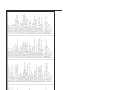
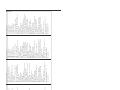
-
 1
1
-
 2
2
-
 3
3
-
 4
4
-
 5
5
-
 6
6
-
 7
7
-
 8
8
-
 9
9
-
 10
10
-
 11
11
-
 12
12
-
 13
13
-
 14
14
-
 15
15
-
 16
16
-
 17
17
-
 18
18
-
 19
19
-
 20
20
-
 21
21
-
 22
22
-
 23
23
-
 24
24
-
 25
25
-
 26
26
-
 27
27
-
 28
28
-
 29
29
-
 30
30
-
 31
31
-
 32
32
-
 33
33
-
 34
34
-
 35
35
-
 36
36
-
 37
37
-
 38
38
-
 39
39
-
 40
40
-
 41
41
-
 42
42
-
 43
43
-
 44
44
-
 45
45
-
 46
46
-
 47
47
-
 48
48
-
 49
49
-
 50
50
-
 51
51
-
 52
52
-
 53
53
-
 54
54
-
 55
55
-
 56
56
-
 57
57
-
 58
58
-
 59
59
-
 60
60
-
 61
61
-
 62
62
-
 63
63
-
 64
64
-
 65
65
-
 66
66
-
 67
67
-
 68
68
-
 69
69
-
 70
70
-
 71
71
-
 72
72


Dometic T 2500 H/HG-LP, T 4000 H/HG-LP, T 5500 H/HG-LP Istruzioni per l'uso
- Tipo
- Istruzioni per l'uso
- Questo manuale è adatto anche per
in altre lingue
- français: Dometic T 2500 H/HG-LP, T 4000 H/HG-LP, T 5500 H/HG-LP Mode d'emploi
- español: Dometic T 2500 H/HG-LP, T 4000 H/HG-LP, T 5500 H/HG-LP Instrucciones de operación
- Deutsch: Dometic T 2500 H/HG-LP, T 4000 H/HG-LP, T 5500 H/HG-LP Bedienungsanleitung
- Nederlands: Dometic T 2500 H/HG-LP, T 4000 H/HG-LP, T 5500 H/HG-LP Handleiding
Documenti correlati
Altri documenti
-
 WTA 5500 Scheda dati
-
Ferm PGM1005 Manuale del proprietario
-
 Mosa GE 10000 HZDM Manuale del proprietario
-
 Mosa Magic Weld 200 Manuale del proprietario
-
Master BLP 33 53 73 103 ET Manuale del proprietario
-
 Mosa GE 12054 HZDT Manuale del proprietario
-
 Mosa GE 35 PS SX Manuale del proprietario
-
-
Master BLP 33 53 73 103 ET Manuale del proprietario
-
Mase MARINER 560 S Manuale del proprietario


