
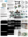
DIN rail mounting
2 channels data
acquisition module
D9 line
Quick Guide • 17/11 • ISTR_Q_D9_1_03_--
viale Indipendenza 56, 27029 - Vigevano (PV)
Tel.: +39 0381 698 71, Fax: +39 0381 698 730
internet site: www.ascontecnologic.com
E-mail: [email protected]
Dimensions
Terminal connectors
99 mm
3.9 in
22.5 mm
0.89 in
6.3 mm
0.25 in
114.5 mm
4.5 in
4 terminal connectors
Power supply/
comm.s
connector
Power supply voltage:
24Vac (-25...+12%) or
24Vdc (-15....+25%)
Termi-
nation
plug
A
B
C
D
Removing the instrument from the DIN rail
Switch the instrument off
12
DIN rail mounting
1
CLICK
2
1 Clip the upper part of the
instrument on the rail;
2 Rotate the instrument
downwards until the click;
1 Lower the spring slide by
inserting a flat-blade
screwdriver as indicated;
2 Turn and lift the instrument
upwards.
Parameters list
In the table that follows are listd the parameters of the controller associated to the correspondent serial ModBus address. For further details,
consult the manual: “gammadue® and deltadue® controller series Serial communications and configuration software”.
Analogue Loop1
Analogue Loop2
Analogue general
Digital
ModBus
address Parameter name Value
Default Modbus User
0Process Value PV
21 Input filter PV1 measure inhibited 0
22 Input shift PV1 measure inhibited 0
92 Loop1 Ref. Value selection local 0
ModBus
address Parameter name Value
Default Modbus User
30 Process Value PV
51 Input filter PV2 measure inhibited 0
52 Input shift PV2 measure inhibited 0
93 Loop2 Ref. Value selection local 0
ModBus
address Parameter name Value
Default Modbus User
60 AL1 alarm threshold 0 0
61 AL2 alarm threshold 0 0
62 AL3 alarm threshold 0 0
63 AL4 alarm threshold 0 0
64 AL1 alarm Hiysteresis 0.5 5
65 AL2 alarm Hysteresis 0.5 5
66 AL3 alarm Hysteresis 0.5 5
67 AL4 alarm Hysteresis 0.5 5
68 AL1 Alarm addressing PV1 0
69 AL1 alarm type disabled 0
70 AL1 Latching/Blocking none 0
71 AL1 Alarm output internal status 0
72 AL2 alarm addressing PV1 0
73 AL2 alarm type disabled 0
74 AL2 Latching/Blocking none 0
75 AL2 alarm output internal status 0
76 AL3 alarm addressing PV1 0
77 AL3 alarm type disabled 0
78 AL3 Latching/Blocking none 0
79 AL3 alarm output internal status 0
80 AL4 alarm addressing PV1 0
81 AL4 alarm type disabled 0
82 AL4 Latching/Blocking none 0
83 AL4 alarm output internal status 0
95 Instrument position alone 0
ModBus
address Parameter Value
0 OP1 digital output 0 = OFF, 1 = ON
1 OP2 digital output 0 = OFF, 1 = ON
2 OP3 logical output 0 = OFF, 1 = ON
3 OP4 logical output 0 = OFF, 1 = ON
4 Alarms acknowledgement 1 = Alarms acknowledge
5 Forcing the Output status 0 = Not influenced,
1 = Forces the OP status to OFF
6 PV1 measure Hold 1 = PV1 locked
7 PV2 measure Hold 1 = PV2 locked
10 PV1 out of range
0 = Valid measure, 1 = Out of range
11 PV2 out of range
0 = Valid measure, 1 = Out of range
12 AL1 alarm status 0 = Normal, 1 = alarm
13 AL2 alarm status 0 = Normal, 1 = alarm
14 AL3 alarm status 0 = Normal, 1 = alarm
15 AL4 alarm status 0 = Normal, 1 = alarm
16 IL1 logic input status 0 = OFF, 1 = ON
17 OP3 input status 0 = OFF, 1 = ON
18 OP4 input status 0 = OFF, 1 = ON
32 NOT OP1 output 0 = Not influenced,
1 = Forces the OP reverse status
33 NOT OP2 output 0 = Not influenced,
1 = Forces the OP reverse status
34 NOT OP3 output 0 = Not influenced,
1 = Forces the OP reverse status
35 NOT OP4 output 0 = Not influenced,
1 = Forces the OP reverse status
Declaration of conformity and manual retrieval
D9 is a rear panel mounting, Class II instrument, it has been
designed with compliance to the European Directives.
All
information about the controller can be found in the Installation
or in
the User Manual:
ISTR_I_D9_E_03_--.pdf
and
ISTR_I_D9_E_03_--.pdf
.
The Manual and the Declaration of Conformity of the instrument
can be downloaded (free of charge) from the web-site:
www.ascontecnologic.com
Once connected to the web-site, search:
D9
;
then click on D9
on the search result list
.
In the lower part of the product page (in any language) is present
the download area with the links to the documents available for
the requested intrument (in the available languages).
Warning!
-
Whenever a failure or a malfunction of the device may cause
dangerous situations for persons, things or animals, please
remember that the plant must be equipped with additional
devices which will guarantee safety.
-
We warrant that the products will be free from defects in
material and workmanship for 18 months from the date of
delivery. Products and components that are subject to wear
due to conditions of use, service life and misuse are not covered
by this warranty.
Disposal
The appliance (or the product) must be disposed of
separately in compliance with the local standards in
force on waste disposal.
Model code
The product code indicates the specific hardware coniguration of the
instrument, that can be modified by specialized engineers only.
Configuration code
A 4 + 4 digits index code follows the model (letters from I... R). This
code can be used to buy a pre-configured controller.
[1] For instance, other thermocouples types, ΔT (with 2 PT100),
custom linearisation etc.
Line D 9
Output OP1 - OP2 B
Relay - Relay 1
Relay - SSR Drive 2
SSR Drive - SSR Drive 3
SSR - SSR 4
SSR - SSR Drive 5
Input type Range PV1 I L
Input type Range PV2 M N
TR Pt100 IEC751
-99.9…300.0°C
-99.9…572.0°F
00
TR Pt100 IEC751 -200…600°C -328…1112°F 01
TC L Fe-Const DIN43710 0…600°C 32…1112°F 02
TCJ Fe-Cu45% Ni IEC584 0…600°C 32…1112°F 03
TC T Cu-CuNi -200…400°C -328…752°F 04
TC K Chromel-Alumel IEC584
0…1200°C 32…2192°F 05
TC S Pt10%Rh-Pt IEC584 0…1600°C 32…2912°F 06
TC R Pt13%Rh-Pt IEC584 0…1600°C 32…2912°F 07
TC B Pt30%Rh Pt6%Rh IEC584 0…1800°C 32…3272°F 08
TC N Nichrosil-Nisil IEC584 0…1200°C 32…2192°F 09
TC E Ni10%Cr-CuNi IEC584 0…600°C 32…1112°F 10
TC NI-NiMo18% 0…1100°C 32…2012°F 11
TC W3%Re-W25%Re 0…2000°C 32…3632°F 12
TC W5%Re-W26%Re 0…2000°C 32…3632°F 13
Dc input 0…50mV linear Engineering units 14
Dc input 10…50mVlinear Engineering units 15
Custom input range [1] 16
Control mode LOOP1 O
Control mode LOOP2 P
ON-OFF reverse action 0
ON-OFF direct action 1
PID single reverse action 2
PID single direct action 3
Output configuration LOOP1 Q
None 0
OP1 1
OP3 2
Output configuration LOOP2 R
None 0
OP2 1
OP4 2
Line Basic Accessories Configuration
1st part
D2 5 B5 D
-E90 0/I L M N
Model:
O P Q R
-
2nd part
Configuration and setting Software
The instrument must be configured using Controller Explorer
(a proprietary free software). The most recent release of Controller
Explorer is downloadable from our web site:
www.ascontecnologic.com
Once connected to this site, click on the banner: Download,
then click on the row: Controller Explorer.
Download the most recent version of the software and, when
present, any upgrade to the program.
Once installed the Software and the upgrades, run the program,
the default communications parameters are:
Transmission speed: 9600 bps;
Protocol: ModBus;
Serial address: 247.
Warning!
When more controllers/instruments are to be installed, keep in
mind that the default serial address always is 247.
For this reason, always connect/power on only 1 not configured
instrument a time, in order to avoid the presence, on the same
network, of 2 instruments with the same address. During the
configuration, assign to each instrument a different serial address.
The "gammadue® and deltadue® controller series Serial
communications and configuration software" manual can be
downloaded from the web site:
www.ascontecnologic.com
As for the other manuals, also this one is present in the lower part
of the product page.
Terminals
LL = 7 mm - 0.28 in. L = 7 mm - 0.28 in.
0.6 x 3.5 mm 0.4 x 2.5 mm
A - B - C - DFeatures Bus/Power Supply
Stripped
wire
Flat blade
screwdriver
Tightening
torque 0.5... 0.6 Nm 0.4... 0.5 Nm
Connections
IL1
TTL
NPN
NO
OP3
5
4
3
2
1
RS485
24V
NC N
L
OP4
mAmV Pt100
13 14 15
Pt100
9 10 11
mV
mA
910
OP1 OP2
IN1
IN2
Power supply
switch
Configuration/
Supervision
Power supply
and serial
communications
bus connector
(female)
External
Shunt
2.5Ω
External
Shunt
2.5Ω
910
13 141413
Plug with termination
resistor for serial
comm.s bus (male)
Mounting several instruments
2 Then, insert the
female 5-pole
connector with
the termination
resistor of the
serial
communications
into the
corresponding
male connector;
3 Wire the 5-pole
male power
supply and serial
communications
connector and
insert it in the
corresponding
female connector;
1
Mounted the instruments on the rail, put them side by side so that the
male side connector fits into the corresponding female connector;
Connector protection
4 When assembled insert the connector protection on both sides.
12
3
4
22.5 x N + 53 mm
50 mm
1.969 in
3
Serial communications connection examples
Configuration
Configuration
Cd-Rom
D9 - 31 max. instruments
Acquisition and centralized supervision
D9 - 31 max. instruments Operator panel
Local control
D9
RS485
RS485
RS485
Removing the module
The electronic module of the
instruments can be extracted
from the housing in order to
allow an easy maintenance,
wiring and setting.
1) Insert the blade of a negative
screwdriver under the I/O
polarized connectors;
2) Moving the screwdriver as
indicated, unplug the
connector from the module;
3) Remove the connector and
repeat the steps in order to
unplug all the external
connections;
Remove/insert the module from/in its housing
5) Firmly grip the front panel in the terminal block area and pull
the module outside the housing.
4) With the blade of the screwdriver, press the two slots
(at the top and bottom of the module) in order to free the
I/O module from the housing;
Re-inserting the module in the housing
In order to correctly re-insert the module in its housing, invert the
previous extracting sequence, paying particular attention in
inserting the printed circuit board in the slots present at the top and
bottom of the case.

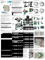
Acquisitore
a 2 canali indipendenti
per guida DIN
linea D9
Quick Guide • 17/11 • ISTR_Q_D9_1_03_--
viale Indipendenza 56, 27029 - Vigevano (PV)
Tel.: +39 0381 698 71, Fax: +39 0381 698 730
internet site: www.ascontecnologic.com
E-mail: [email protected]
Dimensioni
Morsettiere
99 mm
3.9 in
22.5 mm
0.89 in
6.3 mm
0.25 in
114.5 mm
4.5 in
Presa
terminaz.
4 spine morsetti
Spina
alimentazione/
comunicazione
Tensione di alimentazione:
24Vac (-25...+12%) o
24Vdc (-15....+25%)
A
B
C
D
Rimozione dalla guida DIN
Togliere tensione allo strumento
12
Montaggio su guida DIN
1
CLICK
2
1 Agganciare la parte superiore
dello strumento sulla guida;
2 Ruotare lo strumento verso il
basso fino allo scatto;
1 Abbassare la slitta a molla
inserendo un cacciavite a lama
piatta come indicato;
2 Ruotare lo strumento verso
l’alto.
Elenco dei parametri
Nella tabella che segue sono elencati i parametri del regolatore con il relativo indirizzo seriale ModBus.
Per ulteriori informazioni si consulti il manuale: “Configurazione e comunicazione seriale gammadue® e deltadue®”.
Analogici Loop1
Analogici Loop2
Analogici generali
Digitali
Indirizzo
ModBus Nome parametro Valore
Default Modbus Utente
0 Misura PV
21
Costante di tempo filtro misura PV
esclusa 0
22 Correzione della misura PV esclusa 0
92 Selezione del valore di riferimento locale 0
Indirizzo
ModBus Nome parametro Valore
Default Modbus Utente
30 Misura PV
51
Costante di tempo filtro misura PV
esclusa 0
52 Correzione della misura PV esclusa 0
93 Selezione del valore di riferimento locale 0
Indirizzo
ModBus Nome parametro Valore
Default Modbus Utente
60 Soglia Allarme 1 0 0
61 Soglia Allarme 2 0 0
62 Soglia Allarme 3 0 0
63 Soglia Allarme 4 0 0
64 Isteresi Allarme 1 0.5 5
65 Isteresi Allarme 2 0.5 5
66 Isteresi Allarme 3 0.5 5
67 Isteresi Allarme 4 0.5 5
68 Sorgente Allarme 1 PV1 0
69 Tipo Allarme 1 disabilitato 0
70 Latching/Blocking Allarme 1 nessuno 0
71 Uscita Allarme 1 stato interno 0
72 Sorgente Allarme 2 PV2 0
73 Tipo Allarme 2 disabilitato 0
74 Latching/Blocking Allarme 2 nessuno 0
75 Uscita Allarme 2 stato interno 0
76 Sorgente Allarme 3 PV3 0
77 Tipo Allarme 3 disabilitato 0
78 Latching/Blocking Allarme 3 nessuno 0
79 Uscita Allarme 3 stato interno 0
80 Sorgente Allarme 4 PV4 0
81 Tipo Allarme 4 disabilitato 0
82 Latching/Blocking Allarme 4 nessuno 0
83 Uscita Allarme 4 stato interno 0
95 Posizione strumento singolo 0
Indirizzo
ModBus Nome parametro Valore
0 Uscita OP1 0 = OFF, 1 = ON
1 Uscita OP2 0 = OFF, 1 = ON
2 Uscita logica OP3 0 = OFF, 1 = ON
3 Uscita logica OP4 0 = OFF, 1 = ON
4 Tacitazione allarmi in latching 1 = tacita gli allarmi
5 Blocco uscite 0 = non influenzate,
1 = forzate a OFF
6 Hold misura PV1 1 = blocca la misura di PV1
7 Hold misura PV2 1 = blocca la misura di PV2
10 Stato fuoriscala PV1 0 = misura valida,
1 = PV1 fuoriscala
11 Stato fuoriscala PV2 0 = misura valida,
1 = PV2 fuoriscala
12 Stato allarme 1 0 = normale, 1 = allarme
13 Stato allarme 2 0 = normale, 1 = allarme
14 Stato allarme 3 0 = normale, 1 = allarme
15 Stato allarme 4 0 = normale, 1 = allarme
16 Stato ingresso digitale IL1 0 = OFF, 1 = ON
17 Stato ingresso su OP3 0 = OFF, 1 = ON
18 Stato ingresso su OP4 0 = OFF, 1 = ON
32 Inversione uscita OP1 0 = inattiva,
1 = forzatura inversione
33 Inversione uscita OP2 0 = inattiva,
1 = forzatura inversione
34 Inversione uscita OP3 0 = inattiva,
1 = forzatura inversione
35 Inversione uscita OP4 0 = inattiva,
1 = forzatura inversione
Dichiarazione di conformità e manuale istruzioni
Il D9 è uno strumento per montaggio retroquadro di Classe II
progettato per essere conforme alle Direttive europee.
Tutti i dettagli circa l’installazione e l’utilizzo dello strumento sono
inseriti nel manuale di installazione e nel manuale d’uso:
ISTR_I_D9_I_03_--.
pdf
e
ISTR_U_D9_I_03_--.pdf
.
I Manuali e la Dichiarazione di Conformità dello strumento
possono essere scaricati gratuitamente dal sito web:
www.ascontecnologic.com
Una volta collegato il sito internet indicato, cercare:
D9
poi selezionare D9 nell’elenco dei risultati.
Nella parte bassa della pagina dei prodotti (di qualsiasi lingua) è
presente l’area download con i collegamenti ai documenti relativi
al prodotto (nelle lingue disponibili).
Attenzione!
-
Qualora un guasto o un malfunzionamento dell'apparecchio possa
creare situazioni pericolose e/o dannose per persone, cose o
animali si ricorda che l'impianto deve essere predisposto con
dispositivi elettromeccanici aggiuntivi atti a garantire la sicurezza.
-
I prodotti sono coperti da una garanzia di 18 mesi dalla data di
spedizione. Dalla garanzia sono esclusi i prodotti e i componenti
soggetti ad usura per condizioni di utilizzo, vita utile e uso improprio.
Smaltimento
L’apparecchiatura (o il
prodotto) deve essere
oggetto di
raccolta separata in conformità alle vigenti normative
locali in materia di smaltimento.
Codice modello
La sigla del modello identifica le caratteristiche hardware del regola-
tore modificabili solo da personale qualificato.
Codice di configurazione
Un codice di 4 + 4 digit segue il codice modello (lettere I... R). Il codice
di configurazione serve per ordinare lo strumento pre-configurato.
[1] Esempio: altri tipi di termocoppie, ingressi non lineari
definite su specifica, ΔT (con 2 PT100) ecc.
Linea D 9
Uscite OP1 - OP2 B
Relè - Relè 1
Relè - Logica 2
Logica - Logica 3
SSR - SSR 4
SSR - Logica 5
Tipo di ingresso Campo scala PV1 I L
Tipo di ingresso Campo scala PV2 M N
TR Pt100 IEC751
-99.9…300.0°C
-99.9…572.0°F
00
TR Pt100 IEC751 -200…600°C -328…1112°F 01
TC L Fe-Const DIN43710 0…600°C 32…1112°F 02
TCJ Fe-Cu45% Ni IEC584 0…600°C 32…1112°F 03
TC T Cu-CuNi -200…400°C -328…752°F 04
TC K Chromel-Alumel IEC584
0…1200°C 32…2192°F 05
TC S Pt10%Rh-Pt IEC584 0…1600°C 32…2912°F 06
TC R Pt13%Rh-Pt IEC584 0…1600°C 32…2912°F 07
TC B Pt30%Rh Pt6%Rh IEC584 0…1800°C 32…3272°F 08
TC N Nichrosil-Nisil IEC584 0…1200°C 32…2192°F 09
TC E Ni10%Cr-CuNi IEC584 0…600°C 32…1112°F 10
TC NI-NiMo18% 0…1100°C 32…2012°F 11
TC W3%Re-W25%Re 0…2000°C 32…3632°F 12
TC W5%Re-W26%Re 0…2000°C 32…3632°F 13
Ingresso lineare 0…50mV In unità ingegneristiche 14
Ingresso lineare 10…50mV In unità ingegneristiche 15
Ingresso e scala “custom” [1] 16
Tipo di regolazione LOOP1 O
Tipo di regolazione LOOP2 P
ON-OFF ad azione inversa 0
ON-OFF ad azione diretta 1
PID ad azione singola inversa 2
PID ad azione singola diretta 3
Tipo di uscita LOOP1 Q
Nessuna 0
Su OP1 1
Su OP3 2
Tipo di uscita LOOP2 R
Nessuna 0
Su OP2 1
Su OP4 2
Linea Base Accessori Configurazione
1a parte
D9 5 B5 0-0900/I L M N
Modello:
O P Q R
-
2a parte
Software di configurazione e impostazione
Lo strumento deve essere configurato mediante il software Controller
Explorer (programma proprietario gratuito).
La versione più recente del programma Controller Explorer può essere
scaricata dal sito internet:
www.ascontecnologic.com
Collegato il sito internet indicato selezionare: Download
poi cliccare sulla riga: Controller Explorer.
Effettuare il download della versione più recente del programma
più gli eventuali aggiornamenti.
Una volta installato il software e gli aggiornamenti, lanciare il
programma, i parametri di comunicazione di default sono:
Velocità di trasmissione: 9600 bps;
Protocollo: ModBus;
Indirizzo seriale: 247.
Attenzione!
Quando si devono installare più strumenti, porre attenzione al
fatto che l'indirizzo seriale di default è sempre = 247.
Per questa ragfione, alimentare o collegare sempre 1 strumento
per volta in modo da non avere attivi sulla stessa rete 2
strumenti con lo stesso indirizzo seriale.
Assegnare indirizzi diversi ad ogni strumento.
Il manuale "Configurazione e comunicazione seriale
gammadue® e deltadue®" può essere scaricato dal sito:
www.ascontecnologic.com
Come per gli altri manuali, anche quello indicato è presente nella
parte bassa della pagina specifica del prodotto.
IL1
TTL
NPN
NA
Collegamenti
Morsetti
LL = 7 mm - 0.28 in. L = 7 mm - 0.28 in.
0.6 x 3.5 mm 0.4 x 2.5 mm
A - B - C - DCaratteristica Bus/Alimentazione
Filo
spelato
Cacciavite
a taglio
Coppia di
serraggio 0.5... 0.6 Nm 0.4... 0.5 Nm
OP3
5
4
3
2
1
RS485
24V
Interruttore
alimentazione
Configurazione
e Supervisione
NC N
L
Spina bus
alimentazione
e linea seriale
(femmina)
Presa con resistenza
di terminazione linea
seriale (maschio)
OP4
Shunt
esterno
2.5Ω
mA
mV Pt100
13 14 15
Pt100
910 11
mV Shunt
esterno
2.5Ω
mA
910
OP1 OP2
IN1
IN2
13 1413 14
910
12
3
4
3
Installazioni multiple
2 Dopo aver affiancato
tutti gli strumenti
inserire la spina
femmina a 5 poli
con resistenza di
terminazione della
linea seriale
nel
corrispondente
maschio;
3 Cablare il connettore
di alimentazione
sulla spina maschio
a 5 poli ed inserirla
nella corrispondente
femmina;
1
Dopo aver montato gli strumenti sulla guida, affiancarli in modo che il
connettore trasversale si inserisca nel connettore corrispondente;
22.5 x N + 53 mm
protezione connettori
50 mm
1.969 in
4 A montaggio ultimato inserire le protezioni connettori su ambo i lati.
Esempi di collegamento seriale
Configurazione
D9
RS485 CD-ROM con tool
di configurazione
D9 - 31 strumenti max.
Acquisizione e comando centralizzato
RS485
D9 - 31 strumenti max. Pannello operatore
Controllo locale
RS485
Estrazione
Il modulo elettronico dello
strumento può essere estratto
dalla custodia per permettere
una facile manutenzione,
cablaggio e impostazione.
1) Inserire la lama di un
cacciavite sotto la spina
polarizzata di collegamento
degli I/O;
2) Facendo leva col cacciavite
estrarre la spina polarizzata
dal modulo;
3) Sfilare la spina e ripetere
la manovra per rimuovere
tutte le spine che hanno
collegamenti elettrici con
l’esterno;
Estrazione/inserimento del modulo elettronico
5) Afferrare il modulo nella zona dove sono state rimosse le
spine polarizzate e sfilare il modulo dalla custodia.
4) Con il cacciavite premere sui 2 blocchi (superiore ed inferiore)
per liberare il modulo dal contenitore;
Inserimento nella custodia
Per inserire nuovamente il modulo nella custodia, invertire la
sequenza utilizzata per la sua rimozione, facendo attenzione
che il circuito stampato si inserisca correttamente nelle guide
di montaggio.
-
 1
1
-
 2
2


in altre lingue
Documenti correlati
-
Ascon tecnologic D2 Guida Rapida
-
-
-
-
-
-
-
-
-

