SEA USER 1 Manuale del proprietario
- Categoria
- Gate Opener
- Tipo
- Manuale del proprietario
Questo manuale è adatto anche per

USER 1 - 24V
SEA s.r.l.
Zona Ind.le S. Atto - 64020 S. Nicolò a Tordino (TE)
Tel. 00390861.588341 - Fax 00390861.588344
www.seateam.com
e-mail: [email protected]
Italiano
Français
English
Sistemi Elettronici
di Apertura Porte e Cancelli
International registered trademark n. 804888
®
Español
APPAR. ELETTRONICA 24V PER CANCELLI SCORREVOLI E BARRIERA
24V ELECTRONIC CONTROL UNIT FOR SLIDING GATES AND BARRIERS
ARMOIRE ELECTRONIQUE 24V POUR PORTAILS COULISSANTS ET BARRIERES
DISPOSITIVO ELECTRÓNICO 24V PARA CANCELAS CORREDIZOS Y BARRERAS
REV 01 - 12/201067411070
23024060/65

USER 1 - 24V
M4
1 2
M1
M3
M1
1
1
2
2
3
2
+
-
M2
1 2
+
-
Sistemi Elettronici
di Apertura Porte e Cancelli
International registered trademark n. 804888
®
24V Accessori Max 200 mA
24V Accessories Max 200 mA
24V Accessoires Max 200 mA
24V Accesorios Max 200 mA
g
a
/La
m
pe
gi
t
or
e
24V
1
5W
h
i
V Fl
a
s ng l
am
p 2
4
15
W
l
a e
1
La
m
pe
c i
gn
o
t
n
t
2
4V
5W /
2
5
W
La
m
pa
r
a
4V
1 /
S
28
V
Car
i ab
at
er
ie
c t
2
8V
Bat
t
er
y
c
h
ar
ge
r
28
V
C
h
a g
ur
d
e
b
at
t
er
ie
r e
28
b
at
a
V C
ar
g
a er
i s
P
o
i
t
o b
t ia Po
sit
e b t
e y
s iv a
t
e
r /
i
v
a
t r
P
s
if
a
t
t r o
it
i
a e
í
o
it
b e i
e
/
P
s v
o
B t r
a
e
t
a a
t
r
N ga
i
v
o
c
ri
cab
t
e i
a/
N
N
N
t
t
y
h
g
e
g
a
iv
e
b
a
t
e
r
c a
r er
g
a t
e
at
i
f c
h
ar
ge
u
r b
t
er
i
e
g
o c
r
b a
e at
i
v
a ga
at
erí
s
Solo con scheda
caricabatteria / Only with
battery charger card /
Seulement avec
chargeur batterie / Solo
con tarjeta cargabaterías
(Cod.23101105)
M5
1 2
C
o
u e
/
C
o m
o
n
m
n
m
/
C
mn
/
C
o
ue
o u
m
n
n /
n
/
Ante
na A
n
t
e n
a
t
e t
e
A
n
n
n
/
A
n
n
a
e
M6
1 2
ST
R
A T
C u o
mm
om ne
/ C
o
n
/
C
Com ne
o
mu
n/ u
M7
1 2
C
n
o
/
omu
e /
C
mm
o
n
C m
u o neo
n
/
C mu
S AR Pe
d
. AR P
T T /
ST T e
d
.
/
S
T
R
T
Ped
/ST
AR
P
e
d.
A
T
M8
1 2
C
o
un
/
o
m
o
n
/
m e
C m
u /
o uC
om
n
C
m
ne
i r a / d
e
C
o
s
ta
d s
ic
u
e
z
z
S
af
et
y
e
g
T c
d ri
r
a
n h
e
e
s
é
c
u
t
é
/
o
d
i
aC
s
ta
e
s
e
gu
r d
d
67411070 REV 01 - 12/2010
CONNESSIONI / CONNECTIONS /
CONNEXIONS / CONEXIONES

1 2
C mun /
o e
C
o m
o
/m
n
C
m
u
n
/
o
C
o
n
e
mu
B
US
M11
USER 1 - 24V
CONNESSIONI / CONNECTIONS /
CONNEXIONS / CONEXIONES
Enco
der
1
(
V
er
de
)
/ Enc
ode
r
1
(
G
een
)r
n t E o
der
1 V
e
r
)
/
E
n
c
e
r
1 (V
erd
e)
c
(
od
C
m
Co
m
u
ne
/
om
o
n
/
Co
mun
/
C
omune
i
e
.1
L m tch .
F co s
a
A
p
i
i
t
w
i
O
p
1
n
r / s /
i
c
o
u
/
i
n e
r
A
F d
e u se
v
.
F a
l
d
c
a
r
r
p
.n
r
O 1
e a 1
F e
r
C
.1
L i
t
wi
tc
C
l.
/
in
co s
a h
/ i
m s
h 1
in e
co
r
F
e /
F
in
a
d
ca
r r
C
.1
F d
u
se
.1
l
e
r
e a
ie
M9
1 2
m e
n
Co un /
C
o
m
m
o
/
uCom n
/
C
om
u
n
e
SO
P
T
3
JOLLY
RADIO MODULE
Connettore modulo ricevente /
Receiver module connector /
Connecteur module récepteur /
Conector modulo receptor
POWER
DIP SWITCH
ON
ON
1
3
2
4
ON
ON
E
c
o
de
r
1
( ia
c
o)
/
n
d
er
(
Wh
)n B
n
E c
o
1
it
e
E
de
r
1
( lan
/ E
nc
o
d
r
1 B
nc
o
)
nc
o
B
c) e
(
la
m
un
/
C
om
m
on
/
Com
n
/
Co un
eC
o
e u m
Sistemi Elettronici
di Apertura Porte e Cancelli
International registered trademark n. 804888
®
Connettore alimentazione 24V /
24V feed connector /
Connecteur alimentation 24V /
Conector alimentaciùn 24V
PROGR RX
ENCODER
LIMIT SWITCH
Connettore Programmatore Jolly /
Connector Programmer Jolly /
Connecteur Programmateur Jolly /
Conector Programador Jolly
Chius a
a
utoma
t
i
c
a
u
r
/
A
uto a
t
ic
l
o
s
i
n
g
/
m c
F
er e re
a
utoma
t
i
q
ue/
m
tu
Cie
rr
e
a
utom
a
t
i
c
o
I
n
v
er
s o
n
e
mot
or
e/i
Mot
or
e
v
er
i
on
/ r s
I
n
v
er
s on
m
o
te
ur/
i
In
ve
r
s
ó
n motor
i
Atti a
zi
d
i
p
w
i
tc
h
v one
s
/
D p
S
w
itc
h a t
i
at
i
o
n
/
i
c
v
cti ation
D
i
S
t
c
h
/A
v p wi
t
i
a
c
i
i
p swi h
Ac v
ó
n
d tc
S
t
ar
t
i
n
p
a
u
s
a
/
St
a
r
t i
n P
ause
/
St
a
r
t en p
aus
e
/
S
t
art
e
n
pa
u
sa
Connettore programmatore OPEN/
Connector programmer OPEN/
Connecteur programmateur OPEN/
Conector Programador OPEN
o ce
la
to
ll
F
t
o l
lu /
P
h
o
c
e /
P ce l o e ah
o
t
o l
lu
e
/
F to
c
lul
M10
1 2
o
m
Com
u
e /
C
m
on
n
u
o
u
/
C
mn
/
C
mne
o
67411070
N.C.
12V
4V
+
2
REV 01 - 12/2010
1 2 3 4 1 2 3 4

INDEX
English
Sistemi Elettronici
di Apertura Porte e Cancelli
International registered trademark n. 804888
®
USER 1 - 24V
COMPONENTS’ DESCRIPTION ................................................................................................20
GENERAL INFORMATION .........................................................................................................21
START, STOP, PEDESTRIAN START, ANTENNA, PHOTOCELL CONNECTIONS...................22
ENCODER, LIMIT SWITCH, WARNING LAMP, EDGE ..............................................................23
POWER SUPPLY AND MOTORS CONNECTIONS ..................................................................24
SELFLEARNING DEFAULT SETTING .......................................................................................24
WORKING TIMES SELFLEARNING ..........................................................................................25
SETTINGS’ SELECTION ............................................................................................................26
EXTERNAL RECEIVER CONNECTION AND RADIO TRANSMITTER LEARNING ..................27
FUNCTIONING LOGICS.............................................................................................................28
BUS SYSTEM DESCRIPTION ...................................................................................................28
MASTER SLAVE FUNCTION .....................................................................................................29
PROGRAMMER JOLLY PARAMETERS ADJUSTMENT............................................................ 30
CONNECTION OF BATTERIES .................................................................................................32
ALARMS DESCRIPTION ............................................................................................................32
TROUBLE SHOOTING ...............................................................................................................33
INSTRUCTIONS, MAINTENANCE AND GUARANTEE .............................................................33
TERMS OF SALE........................................................................................................................65
19
67411070 REV 01 - 12/2010

DESCRIPTION OF THE COMPONENTS
English
Sistemi Elettronici
di Apertura Porte e Cancelli
International registered trademark n. 804888
®
LED1 = Encoder ON - Encoder OFF
LED2 = Pause adjustment
LED3 = TX Programming
LED4 = Slowdown speed adjustment
LED5 = Functioning logics
LED6 = Motors speed
LED7 = Encoder
LED8 = Limit switch in opening
LED9 = Limit switch in closing
LED10 A = Led for SET
LED11 B = Led for SET
LED12 C = Led for SET
LED13 = Start
LED14 = Pedestrian Start
LED15 = Security edge
LED16 = Stop
LED17 = Photo
LED18 = Indicator BUS
LED19 = Battery Ok
LED20 = Unloaded Battery
LED21 = Broken fuse
LED22 = 24Vaux condition
LED23 = Warning lamp condition
SET = Setting
MENU = Selection
M1 = Connection to battery charger
M2 = 24Vaux exit
M3 = Motor power supply
M4 = Warning lamp 24V 15W
M5 = Antenna
M6 = Start
M7 = Pedestrian start
M8 = Security edge
M9 = Stop
M10 = Photocell
M11 = BUS
CNE = Encoder connector
CNF = Limit switch connector
CMD = Jolly programmer connector
CMR = Receiver module connector
CALM = 24V power supply connector
CPO = Programmer connector OPEN
CRC = Control unit reprogramming connector
µC = Micro-controller
DSW1 = Automatic closing/Start in pause
DSW2 = Opening direction/Dip Switch activation
USER 1 - 24V
67411070
M1 M2 M3 M4
- S +
24Vaux
Motor
Light
CMR
CMD
ENCODER
LIMIT SWITCH
DSW1
DSW2
SET
MENU
M5 M6 M7 M8 M9 M10 M11
Ant. Start Ped. Edge Stop Photo Bus
CALM
LED 22
LED 23
LED 8
LED 9
LED 7
LED 10
LED 11
LED 12
LED 1
LED 2
LED 3
LED 4
LED 5
LED 6
LED 19
LED 20
LED 18
LED 14
LED 15
LED 16
LED 17
LED 13
LED 21
SET
MENU
GATE TYPE
PAUSE
TX
SLOW D. SPEED
LOGIC
SPEED
SET LEDS
A B C
BATT OK BATT LOW
ENCODER
START PED S.EDGE STOP
PHOTO
BUS
FLASH
SET MOT PWR
FLASH
SET MOT PWR
LSC
LSO
FUSE
LIGHT
24Vaux
1
2
3
4
FLASH
SET MOT TYPE
FLASH
SET MOT TYPE
SET FUNCTION
AUTO CLOSE
START ON PAUSE
DIRECTION REVERSE
DIP DISABLE
1
2
3
4
REV 01 - 12/2010
20

English
GENERAL INFORMATION
The information in this section of the manual are only for technicians or for qualified or authorized installers.
GENERAL CHARACTERISTICS
The USER 1 24V control unit has been designed to manage one low voltage motor with or without electronic limit switches.
It is of very small dimensions and besides the possibility to adjust motor speed, amperemetric anti squeezing sensitivity, leaf
delay in closing, pausing time, it is also possible to manage a display, through which it is possible to control a lot of management
functions and the maintenance of the control unit. The most important change however concerns the presence of a BUS
connector with two wires, through which it is possible to connect accessories as photocells, flashing lamp, key switch and so
on,... connecting only two cables with the control unit. The self- learning of working time can be done automatically.
Sistemi Elettronici
di Apertura Porte e Cancelli
International registered trademark n. 804888
®
TECHNICAL SPECIFICATIONS
Control unit power supply
Absorption in stand by
Max. motor charge
Max. accessories charge
Max. Flash light charge
Environment temperature
Protection fuse (24V accessories)
Function logic
Opening/closing time
Time of pause
Thrust
Slow down
Input on connecting terminal
Output on connecting terminal
Board dimensions
Specifications of optional batteries
Specifications of external enclosure
Special accessories
24 V
90 mA
90 W x 2
24V 250mA
24V 15W max.
-20°C +50°C
F1 (2A)
Automatic/Step by Step 1/S. By Step 2/Sec./Dead man
In selflearning in programming phase
Adjustable
Adjustable Opening and Closing
Adjustable
Battery power supply / Total opening / Pedestrian
opening adjustable / Edge/ Stop / Limit switch
opening and closing / Encoder/ BUS accessories
Power supply accessories 24V / Motors 24V /
Flashing lamp 24V / BUS
156 x 100 mm
24V Pb 2Ah min.
305 x 225 x 125 mm - Ip55
Battery charger card (cod.23101105), Relay card
for courtesy light or bolt lock (cod.23101106),
Programmer JOLLY (cod.23105276), Programmer
OPEN (cod.23105290), Photocell SUNSET BUS
(cod.23102075)
USER 1 - 24V
67411070 REV 01 - 12/2010
21

START (N.O.)
An impulse given to this contact opens and closes the automation depending onthe selected logic It
can be given by a key switch, a keypad, etc. To connect the other devices refer to the related
instructions leaflets. (ie. loop detectors and proximity switches)
Note1: In DEAD MAN logic it is necessary to keep pressed the Start for the opening of the
automation.
PEDESTRIAN START (N.O.)
To obtain a partial opening connect the key-button wires as in the figure. It is possible to connect other
command devices (push button board, radio receiver, keypad).
Note1: The contact for partial opening is a N.O. Contact (Normally open)
Nota2: In manual logic it is necessary to keep pressed the Start Ped. To re-close the automation.
STOP (N.C.)
The pressure on this button immediately stops the motor in any condition/position. A start command
is needed to re-start the movement.
After a stop the motor always re-starts in closing.
Notice: If the stop button is not used it is not necessery to close the N.C. contact between the clamps
1 and 2 of M9 as the absence of the stop is revealed during the selflearning phase of the times.
N.O.
-
1
2
1
2
M7
N.C.
-
1
2
1
2
M9
N.O.
-
1
2
1
2
M6
Can be activated through the Jolly programmer or modifying either the PHOTO entry or the PEDESTRIAN entry.
In both cases it’s a N.O. contact which provoques the opening of the automation keeping it open until it is
activated. When it’s released, the gate attends the set pausing time and executes the reclosing.
Note2: When activated on the pedestrian entry, the pedestrian will be disabled also on the radio transmitter.
Note3: In case of intervention of a security device during the timer (Stop, Ammeter, Edge), to restore the
movement it will be necessary to give a start impulse.
Note4: In case of no power supply with open gate and active Timer the control unit will restore its use, otherwise
if during restore of the power supply the TIMER is not activated it will be necessary to give a start impulse for
the reclosing.
JOLLY OPTIONS
Activation TIMER: this entry can be transformed into TIMER (See TIMER)
Pedestrian opening space : Linearly adjustable from 30% to 100%.
START - STOP - PEDESTRIAN START - ANTENNA -
PHOTOCELL
Photocell 1 Connection
When the ray of the photocell is crossed, and the automation is in phase of closing it reverses its
movement.
Note: If the photocell is not connected, put a jumper between the clamps 1 and 2 of (M10).
+ = 24V - = 0V C = Connection Com = Common
The photocell is also usable in connection with BUS photocells.
JOLLY OPTION
TIMER
67411070
M
2
5M
M6
M7
M9
M0
1
USER 1 - 24V
1
2
1
2
M5
GND
Sistemi Elettronici
di Apertura Porte e Cancelli
International registered trademark n. 804888
®
1 2
1 2
M2
RX
TX
Com
C
.
N
.
1
2
1
2
M10
-
+
-
+
-
+ 24V
24Vaux max 200 mA
JOLLY OPTION
Through the Jolly programmer it is
possible to chose when having
tension on the 24Vaux output. The
options are: always, only during
opening, only during cycle, only
before opening or only during pause.
ANTENNA
Connect the antenna
as in the figure.
English
REV 01 - 12/2010
22
JOLLY OPTIONS
FOTOCLOSE activation: If activated when the photocell is crossed during the pause, the gate
interrupts the pause and immediately closes again.
TIMER activation: If the entry is activated it turns into a N.O. entry with TIMER function (see TIMER).
FOTOOPEN activation: If activated the photocell blocks the movement as long as it’s busy, when released it
opens.
FOT PARK activation: in opening it is not active; when during the pause ”closing with photo” and “automatic
closing” are activated it commands the closing when released, otherwise it’s not active; in closing it stops the
movement as long as it is busy, when released the closing continues.
FOTO STOP activation: When activated before the opening the photocell blocks the automation as long as it
is busy, during the opening it will be ignored. In closing the intervention of the photocell causes the reopening.
Activation PHOTO CLOSE IMMEDIATELY: The photocell stops the gate as long as it is occupied in both
opening and closing, when released it gives a closing command.

It is possible to connect an active safety edge on the
terminal M8. If this device is pressed it opens the
contact causing a partial inversion of the movement
both in opening and in closing. If not used bridge
the contacts 1 and 2 of M8. Note: contact N.C.
Sistemi Elettronici
di Apertura Porte e Cancelli
International registered trademark n. 804888
®
Limit switch
For the functioning the presence of both limit
switches in closing and in opening is necessary.
Encoder / Ammeter sensor
The encoder is a device that allows to reveal possible obstacles during the opening and the closing of
the gate. When this device intervenes in opening it causes the inversion of the movement for around
a second, if it intervenes in closing it causes the total reopening.
Note 1: Such function is active through an ammeter sensor on the control board. It is not
necessary to mount any external devices for the respect of legislation.
Note2: The ammeter sensitivity is adjustable both in opening and in closing through the
JOLLY terminal. On the control unit the torque can be adjusted in 4 steps: low, middle,
middle high, high and will be the same in opening and closing. With high torque the gate
reverses after 5 seconds.
Attention: after each intervention of the ammeter sensor it is necessary to give a start impulse
to restore the movement.
Costa di sicurezza
1
2
M8
For the right functioning of the limit switch, the movement direction of the motor and the
respective busy limit switches must correspond. Through DIP3 it is possible to
exchange contemporarily the direction of the motor and of the limit switches.
Note: if during programming phase the motor and limit switch times should not
be in phase between them, the gate will start in closing, it stops and will not
complete the selflearning of the times, at this point it will be necessary to
switch off the tension and to invert the cables of the motor and to eventually
exchange the motor direction on DIP 3. The first movement in selflearning must
always be executed in closing.
Com = Common
C = Contact
M4
1
2
1
2
JOLLY functions:
1) With the Jolly programmer such function is tied up to the presence of at least
one limit switch and it’s possible to activate the function anti-intrusion. When the
limit switch is free it forces the motor to re-close.
2) With the Jolly programmer it is possible to exchange the motor and the limit
switch without setting DIP3 of the control unit.
JOLLY functions:
It is possible to activate a pre-flashing of 3 seconds before activating the automation, on setting pre-
flashing on ON, through the Jolly programmer. Furthermore from the flashing lamp it is possible to verify
some alarm signals. See alarms indications.
Through the Jolly programmer it is possible to set this exit with fixed flashing also when the gate is not
moving or it is possible to change this exit into control lamp. In such case all the indications of alarm
remain on the warning lamp as long as they are active.
JOLLY FUNCTIONS:
It is possible to activate the balanced edge 8K2, in this
case the edge contact will be controled by a specific
value of resistance revealing the eventuel unintentional
short circuit of the device. In case of an unbalance of the
device the corresponding led of the terminal board M8
will flash quickly.
ENCODER - LIMIT SWITCH
JOLLY functions: With the JOLLY programmer the torque parameters can be adjusted linearly
from 10% to 100% on each single motor. Furthermore, they are differentiable between opening and
closing.
Flashing Lamp 24V 15W (Warning lamp )
The warning lamp advises that the automatic gate is moving with 1 flash /second in opening and 2
flashes / second in closing. During pause it remains fixed on.
Connect the cables of the warning lamp as shown in the figure. The pre-flashing function can be
activated with the Jolly terminal or with Led 4 of the menu through the SET and MENU buttons.
SECURITY EDGE AND WARNING LAMP
English
USER 1 - 24V
67411070
Limit
Switch
M4
M8
Limit
Switch
REV 01 - 12/2010
23

Sistemi Elettronici
di Apertura Porte e Cancelli
International registered trademark n. 804888
®
MOTOR POWER SUPPLY
3,6 A delayed fuse on 230V ~ power supply .
6,3A delayed fuse on 115V ~ power supply.
Power input
Input for the connection of the electric power.
P = PHASE - LIVE
N = NEUTRAL
G = GROUND
NOTICE: for the connection to the
electric power see the law in force.
English
USER 1 - 24V
M3
2
1
G N P
G N
115V~
o
230V~
P
M+
M-
M3
1 2
Motor
connection
P N G
M+ M-
The control unit is pre-set with the default settings, to learn the working times it is sufficient to press the Menu button once
and to hold pressed the SET buttonuntil the motors start in closing. The settings of DEFAULT are: AUTOMATIC LOGIC,
ENCODER OFF, SPEED 80% , PRE-FLASHING OFF, PAUSE 10S., TORQUE 75%, SLOWDOWN SPEED 40%, LEARNING SPEED 80%,
ACCELERATION 70%, DECELARATION 30%, LEAF STROKE OFF, ANTI-INTRUSION OFF, SELFTEST OFF, PEDESTRIAN 30%,
PHOTO OPENING OFF, MAX CYCLES 100000, SLIDING MOTOR TYPE, WARNING LAMP NORMAL, PHOTO/TIMER OFF,
PEDESTRIAN/TIMER OFF, CLOS.FOTO OFF, BALANCED EDGE OFF, 24Vaux ALWAYS, START IN PAUSE OFF, AUTOMATIC
CLOSING OFF. IF YOU WANT TO RESTORE THE DEFAULT SETTINGS JUST SWITCH ON THE CONTROL UNIT KEEPING PRESSED
THE BOUTONS MENU AND SET CONTEMPORARILY.
SELFLEARNING WITH DEFAULT PARAMETERS
6741107067411070
5 m
4 m
3 m
For the application on the VERG it is recommended
to use the speed levels indicated on the following
board:
LED 12C RED
LED 10A GREEN
LED 11B YELLOW
REV 01 - 12/2010
24
CONFIGURATION FOR VERG
M3
P N G

A) Select LED 1 of the self-learning through the MENU button, with LED 1 turned on press button SET to choose the function
modality: -Led L10 A green on = Encoder ON -Led L11 B yellow ON = Encoder OFF
B) Once the functioning modality has been chosen, always with Led10 A switched on, hold pressed SET up to the departure of the
motors in closing and then release the button.
Sistemi Elettronici
di Apertura Porte e Cancelli
International registered trademark n. 804888
®
GREEN
YELLOW
RED
WORKING TIMES SELF LEARNING
Note1: it is not necessary to put a jumper between the STOP, PHOTOCELL contacts if they are not used. If
they are used during selflearning phase they must stay (N.C.).
Note2: If accessories are connected on the BUS, align the photocells before programming, as shown in the
description of the BUS system.
1) Make sure that each accessory (photocells, push buttons, and so on) works properly.
2)If necessary adjust the self-learning speed through the palm user.
3)Disconnect the power supply (Fig. 1), release the motor (Fig. 2) and put the leaves manually next to the
stop in closing (Fig. 3-4). Reset the mechanical lock (Fig. 5)
4) Connect the control board to the power supply (Fig.6).
Fig. 1
FF
O
5) Select the desired type of motor; use as shown on pag. 26 or through JOLLY programmer.
6) Press the button “SET” until the led of the color corresponding to the type of application (Encoder ON, Encoder OFF) switches
on.
7) Hold pressed the button “SET” until the motor starts in closing and then release the button.
Note: If FOTOBUS are present, check their alignment and give a new impulse on SET to start the programming.
Note: If the motor starts in opening, switch of the power supply and set DIP 3 on ON or if you have a Jolly terminal, activate the
motor and limit switch exchange function. If the motor starts in closing and stops, switch off the power supply and invert the cable
of the motor, afterwards repeat the procedure starting from step 4.
Note: If you do not have a Jolly terminal the functions of the DIPs on board of the control unit can be activated setting DIP4 on ON.
If DIP4 is activated the functions which can be activated through DIP cannot be changed through the Jolly terminal.
8) The motor will close with the set speed.
9) After having reached the limit switch of closing it automatically will execute an opening cycle (Fig.7). After having reached the
limit switch in opening it will automatically execute a closing cycle.
10) Wait for the end of the closing of the leaf (Fig.8). The self-learning is done.
B) Press the “IMP” button till the Led of the colour
which corresponds to the type of installation (Encoder
ON or Encoder OFF) turnes on.
Keep pressed the button “SET” till the departure of the
motor in closing and then release the button.
A) Press the “Menu” button so that to turn on the LED1
JOLLY functions:
1) With the JOLLY
programmer it is possible to start the
programming without using the MENU
and SET bouton.
2) With the JOLLY programmer it is
possible to choose the type of motor
and the type of application without
using the MENU and SET boutons.
English
USER 1 - 24V
Fig.6
O
N
A
Fig. 2
Fig. 5
Fig. 7
Fig. 3 Fig. 8
LED1
LED10 A
LED11 B
LED12 C
SET
MENU
PROGRAMMING
67411070
Fig. 4
REV 01 - 12/2010
25

USER 1 - 24V
Sistemi Elettronici
di Apertura Porte e Cancelli
International registered trademark n. 804888
®
SELECTION OF THE SETTINGS
The adjustments of the control unit are executed through the buttons "MENU" and "SET” .
Pressing the "MENU” button you select the Leds corresponding to the various functions to be set, pressing the “SET” button you select the leds
corresponding to the desired values inside every single function.
Selecting LED 2 with the“MENU" button you enter into pausing time regulation, with LED 2 turned on, hold pressed the selected button "SET” for the desired time of pause.
According to the colour that the leds 10 A,11 B and 12 C will assume it will be possible to have an order of the length of the set time of pause. If the button is released and pressed
again the time of pause will be annulled.
Led L10 A green turned on Time of pause <15 S.
Led L11B yellow turned on Time of pause <45 S.
Led L12 C red turned on Time of break >45 S. up to 180 S.
Selecting LED 4 with the “MENU" button you enter into the slowdown speed adjustment, with LED 4 turned on, press the button "SET” till to select the desired leaf delay,
observing the colours of the leds 10 A, 11 B and 12 C.
Led L10 A green slowdown speed 30%
Led L11 B yellow slowdown speed 35%
Led L10 A - Led L11 B Green-yellow slowdown speed 45%
Led L10 A - Led L12 C Green-red slowdown speed 50%
Selecting LED 5 with the “MENU" button you enter into the choice of the functioning logics, with LED 5 turned on, press the button "SET” till to select the desired logic, observing
the colours of the Leds 10 A, 11 B and 12 C.
Led L10 A green on dead man logic
Led L11 B yellow turned on automatic logic
Led L12 C red turned on security logic
Led L10 A green and L11 B yellow step by step type 1 logic
Led L11 B yellow and L 12 C red Step by step type 2 logic
Led L10A green and Led L12C red switched on 2 pushbutton logic
Selecting LED 5 with the “MENU" button you enter into the choice of the motors' speed, with LED 5 turned on, press the button "SET” till to select the desired speed, observing
the colours of the leds 10 A, 11 B and 12 C.
Led L10 A green turned on slow speed
Led L11 B yellow turned on middle speed
Led L12 C red turned on high speed
Hold pressed “SET” for more then 5 seconds to annul the executed number of cycles
Selecting LED 1 and LED 2 (with alternate flashing) with the “MENU” button you enter into the motor torque adjustment. With LED 1 and LED 2 flashing alternatively keep
pressed the button “SET” while selecting the desired torque, observing the color of the LEDS 10 A, 11 B, 12 C.
Led L10 A green turned on, torque = Low
Led L11 B yellow turned on, torque = Middle
Led L12 C red turned on, torque = Middle high
Led L10 A, L11 B and L12 C turned on, troque = High
Selecting LEDS 5 and 6 (with alternate flashing) with the “MENU” button you enter into the choice of the type of motor that you are using.
Note: In default the control unit is set on sliding motor.
Led L 10 A green sliding
Led L 11 B yellow barrier
Led L12 C red VERG
Led L 10 A green, Led L 11 B yellow JOINT
Selecting with the pusbutton “MENU” LEDs 3 and 4 with alternated flashing, you enter into the choice of setting the control unit as MASTER or as SLAVE.
Led L 10A, L 11B, L 12C turned on MASTER
Led L 10A, L 11B, L 12C turned off SLAVE
After 5 seconds without having pressed any button, the parameters' adjustment function will be automatically left.
If the control unit turns on when holding pressed the buttons “MENU” and “SET” contemporarily, the control unit will start with the DEFAULT parameter (see
preceding page).
JOLLY function: With the JOLLY programmer it is possible to adjust linearly this parameter without using the MENU and SET buttons.
JOLLY function: With the JOLLY programmer it is possible to change this parameter without using the MENU and SET buttons.
JOLLY function: With the JOLLY programmer it is possible to select the logic without using the MENU and SET buttons on the control unit.
JOLLY function: With the JOLLY programmer it is possible to select the speed without using the MENU and SET buttons on the control unit.
JOLLY function: With the Jolly programmer this parameter is adjustable linearly and differentiable for single opening direction without
using the SET and MENU buttons on the control unit.
JOLLY function: With the Jolly programmer it is possible to select the motor type without using the SET and MENU button on the control unit.
PAUSE
LOGICS
SPEED
English
GREEN
YELLOW
PROGRAMMING
SLOWDOWN
SPEED
TX PROGRAMMING
67411070
JOLLY function: with the Jolly programmer it is possible to select the card as MASTER or SLAVE without using the SET and MENU buttons on board of the card.
SET
MENU
LED10 A
LED11 B
RED
LED12 C
LED1
LED2
LED4
LED3
LED5
LED6
REV 01 - 12/2010
26

M2
M6
M7
!!
Sistemi Elettronici
di Apertura Porte e Cancelli
International registered trademark n. 804888
®
EXTERNAL RECEIVER
Example: Connection of a
radio receiver
For the connection of the
receiver refer to the relative
instructions manual.
RADIO TRANSMITTER SELF LEARNING
WITH RECEIVER ON BOARD OF CONTROL UNIT
Notes:
- Enter radio transmitters learning only when the working cycle stops and the gate is closed.
- It’s possible to memorize up to 800 codes (buttons).
- If all available codes have alredy been memorized and you try to memorize a further code, the led 12 C (red) will flash for signalling the error.
- If the board receives a code which was already associated to another function it will be updated with the new function.
English
WARNING: Make the radio transmitters programming before you connect the antenna and insert the receiver into the
special CMR connector (if available) with turned off control unit. (The control unit automatically recognizes if the receiver is a RF or
RF Roll module)
Note: With a RF module it will be possible to use only 12 bit radio transmitters, that are Coccinella Dip and Copy and Smart Dual.
With RF Roll module it will be possible to use only Coccinella Roll radio transmitters.
1. Select LED 3 with the MENU push button, at this point press the button “SET” and the LED 3 will flash together with the LED 10 A (green) to
signal that it waits for a code to be associated to the total opening;
2. Press the desired button of the radio transmitter, the LED 10 A (green) will turn off to signal the memorisation of the data; now it returns to
flash for 5 seconds waiting for other codes.
3. If it is desired to also associate a command to the pedestrian start, press SET again, the LED 11 B (yellow) will flash for signalling that it is
waiting for a code to be associated to the pedestrian opening;
4. Press the desired button of the radio transmitter, LED 11 B will turn off to signal the memorisation of the data; now it will turn to flash waiting for
other codes to be associated to the pedestrian start. If no other buttons are pressed within 5 seconds the programming will be left.
5. At this point it is possible to press the desired button of the radio transmitter and the LEDS 10 A,11 B, 12 C (green, yellow, red) will show the
available memory, LED10 A (green) shows the occupied memory, less than 50%, LED 11 B (yellow) shows the occupied memory, more than
50%, LED 12 C (red) full memory.
6. To delet all memorized codes keep pressed for more than 5 seconds the adjusted button until the LEDS yellow B, red C and green A will flash
contemporarily to confirm the cancellation.
JOLLY functions: It is possible to monitor the state of occupation of the of the radio transmitter memory.
1
2
1
2
2
1
1
2
1
2
2
1
r
t
S
ta
Sa
t e
d
t
r p
Co
m
om
C
C
mo
+
-
24V
GREEN
YELLOW
RED
USER 1 - 24V
LED10 A
LED11 B
LED12 C
SET
MENU
LED3
M
2
M6
M
7
67411070
TX PROGRAMMING
REV 01 - 12/2010
27

DESCRIPTION OF THE BUS SYSTEM
The BUS is a connecting system through which it is possible to connect different accessories among which: photocells, key switches, warning
lamps, numerical keyboards and key selectors, all in parallel on the same entry and all through two only threads. This system therefore allows
to eliminate the two threads of the power supply for the accessories, therefore every accessory will be equiped with only two threads. Every
accessory is equiped with a rotating changer, which allows to join the various devices according to a numerical sequence which defines the
particular function assigned to that accessory.
FUNCTION LOGIC
Photocells BUS addressing
Rotating Changer on TX and RX on 0 or 1 = photocell active only in opening Rotating Changer on TX and RX on 2 or 3 = photocell active only
in closing Rotating changer on TX and RX on 4 = photocell both in opening and in closing.
The positions from 6 to 9 are interpreted as active photocells both in closing and in opening.
Note: Two couples of photocells with the same function have to have a different number. For ex. on two couples in closing TX and RX of the first
one will have the number 2, TX and RX of the second couple will have the number 3.
English
Sistemi Elettronici
di Apertura Porte e Cancelli
International registered trademark n. 804888
®
Photocells' alignment
If photocells are connected on the BUS it is necessary to line up the same before programming. To do the alignment it is necessary to start a
self-learning cycle of the times. At this point, the gate will stand still, as long as the photocells are not lined up. Once the photocells have been
lined up, push the SET button to restart the self-learning of the times.
AUTOMATIC LOGIC
A start impulse opens the gate. A second impluse during the opening will not be accepted.
A start impulse during closing reverses the movement.
To activate the automatic re-closing put DIP1 and DIP4 on ON.
With DIP2 and DIP4 on ON start in pause is activated
SECURITY LOGIC
A start impulse opens the gate. A second impulse during opening reverses the movement.
A start impulse during closing reverses the movement.
To activate the automatic re-closing put DIP1 and DIP4 on ON.
With DIP2 and DIP4 on ON start in pause is activated.
STEP BY STEP TYPE 1 LOGIC
The start impulse follows the OPEN-STOP-CLOSE-STOP-OPEN logic.
To activate the automatic re-closing put DIP1 on ON.
With DIP2 it is possible to chose whether to make accept the start in pause or not.
STEP BY STEP TYPE 2 LOGIC
The start impulse follows the OPEN-STOP-CLOSE -OPEN logic.
To activate the automatic re-closing put DIP1 on ON.
With DIP2 it is possible to chose whether to make accpet the start in pause or not.
DEAD MAN LOGIC
The gate opens as long as the START button of opening is pressed; releasing it the gate stops. The gate closes as long as the button connected to the PEDESTRIAN START is
pressed; releasing it the gate stops. To execute complete opening and/or closing cycles the related pushbuttons must be constantly pressed.
2 PUSHBUTTONS LOGIC
One start opens, one pedestrian start closes. In opening the closing will not be accepted. In closing a start command reopens, a pedestrian start command (closes) will be
ignored.
JOLLY function: With the JOLLY programmer it is possible to select the logic without using the SET and MENU buttons on
the control unit.
USER 1 - 24V
Jolly option:
If you dispose of a Jolly programmer it is possible to
activate the automatic reclosing and the start in
pause from the programmer without accessing the
control unit.
M11
RX
RX
TX
TX
2
1
2
1
M11
Initialization BUS
Connect all the devices in parallel on the clamp M11 or in parallel between them.
At the lighting of the control unit make sure that the LED13 (red) performs some fast flashes, at this point, if the red led remains turned on this
means that there is an error on the BUS, signalled from the display or by 8 flashes on the warning lamp, but if the red led will keep on flashing
slowly the BUS is perfectly working.
NOTE: To repeat the search of the peripheral BUS in case of BUS error, press contemporarily the buttons + and - of the display, or
press the button until LED 11 B turns on . At this point keep pressed SET as long as LED 11 B does not turn off and LED 10 A turns on.
67411070 REV 01 - 12/2010
28

USER 1 - 24V
Sistemi Elettronici
di Apertura Porte e Cancelli
International registered trademark n. 804888
®
67411070
MASTER-SLAVE FUNCTION
MASTER
SLAVE
To set an installation with two motors in MASTER-SLAVE function it is recommended to do as follows:
1) Set the two motors as if they were two independent installations, make sure that the individual motor works
properly and that the limit switches (when present) are read properly.
2) Once sure of the correct functioning connect the control unit MASTER to the control unit SLAVE through the BUS
with two cables paying especially attention to keep the polarity of the cables.
3)Now set the control unit, which has to manage the commands and motor 1 (photocell, keyswitch, STOP, safety
edge etc.) as MASTER and the other one which will move motor 2 as SLAVE.
To set the MASTER, scroll through the menu until you have found the two central LEDs (TX and SLOW DOWN
SPEED) so that the LEDs blink alternately, and set the SET led (10 A, 11 B and 12 C) so that all three leds are off.
Execute the same operation on the SLAVE control unit, setting the SET led (10 A, 11 B and 12 C) so that all three leds
stay on. If you have a PALM USER ( JOLLY) it is sufficient to choose MASTER or SLAVE in the functions list.
4) Now search the BUS devices as described in the note on the preceding page.
5) Follow up the selflearning of the times of the MASTER control unit.
Note 1: All these operations can also be managed through the PALM USER (JOLLY).
Note 2: On the SLAVE it is possible to set the following functions only: torque, speed, motor type, slowdown speed,
acceleration, deceleration, position recovery, 24V aux and motor inversion. All other parameters will be set only by
the MASTER control unit.
M1 M2 M3 M4
- S +
24Vaux
Motor
Light
CMR
CMD
ENCODER
LIMIT SWITCH
DSW1
DSW2
SET
MENU
M5 M6 M7 M8 M9 M10 M11
Ant. Start Ped. Edge Stop Photo Bus
CALM
LED 22
LED 23
LED 8
LED 9
LED 7
LED 10
LED 11
LED 12
LED 1
LED 2
LED 3
LED 4
LED 5
LED 6
LED 19
LED 20
LED 18
LED 14
LED 15
LED 16
LED 17
LED 13
LED 21
SET
MENU
GATE TYPE
PAUSE
TX
SLOW D. SPEED
LOGIC
SPEED
SET LEDS
A B C
BATT OK BATT LOW
ENCODER
START PED S.EDGE STOP
PHOTO
BUS
FLASH
SET MOT PWR
FLASH
SET MOT PWR
LSC
LSO
FUSE
LIGHT
24Vaux
1
2
3
4
FLASH
SET MOT TYPE
FLASH
SET MOT TYPE
SET FUNCTION
AUTO CLOSE
START ON PAUSE
DIRECTION REVERSE
DIP DISABLE
1
2
3
4
English
REV 01 - 12/2010
29

English
Sistemi Elettronici
di Apertura Porte e Cancelli
International registered trademark n. 804888
®
Screen 4
Screen 5
Motor (Sliding) (Barrier) (Joint)
Screen 1
Language: Italian With buttons + and - it is possible to modify the language
The arrow shows that the
parameter is modifiable with the
buttons + and -
Screen 6
Screen 7
Screen 8
Indicates the type of motor set
Speed [30÷100 ] adjusts the motors’ speed
Sl. speed [30÷100 ] adjusts the slow down speed
Lear. Speed. [30÷100 ] adjusts the learning speed
Photocell Tx1 [OK-NP] (peripheral reveal - not present)
Photocell Tx2 [OK-NP] (peripheral reveal - not present)
Photocell TX3 [OK-NP] (peripheral reveal - not present)
Photocell TX4 [OK-NP] (peripheral reveal - not present)
Photocell TX5 [OK-NP] (peripheral reveal - not present)
Photocell Rx1 [OK-NP] (peripheral reveal - not present)
Photocell RX2 [OK-NP] (peripheral reveal - not present)
Photocell Rx3 [OK-NP] (peripheral reveal - not present)
Photocell RX4 [OK-NP] (peripheral reveal - not present)
Photocell RX5 [OK-NP] (peripheral reveal - not present)
The screens 4, 5, 6, 7, 8 and 9
show the type of accessory on the
BUS.
PROGRAMMER JOLLY PARAMETERS ADJUSTMENT
USER 1 - 24V
The JOLLY programmer allows to keep under control and to change all parameters of the control unit without need to use the SET
and MENU buttons of the control unit. Furthermore, it is essential for the initial setting of some parameters which are not settable
directly on the control unit which are: selftest photocell, photocell in opening, anti-intrusion, separate regulation of the motor
torque in opening and closing, slow-down speed, learning speed, acceleration, deceleration, leaf stroke, number of cycles,
pedestrian opening, foto/timer, ped/Timer, 24Vaux, control lamp, balanced edge, closing with photocell.
Note: Through the JOLLY programmer it is also possible to start the selflearning of the working times.
67411070
Cycle Automat./Secur./Step by step1/Step by step2/Dead man/
2 boutons
Time of pause [0÷120]s (time of pause in seconds)
Encoder on/off (function with encoder, not implemented)
Screen 2
Shows the working logic
adjusted on board of the control
unit.
Screen 3
Note: The alignment appears only if
photocells are present on the BUS.
Learning on alignment/off (signalling of the execution of
the learning)
32
Cicli exec. [0÷2 ] (number of executed cycles)
Mem. free [0÷100]% (percentage of available
memory for the learning of remote controls)
Modality Master/Slave
Screen 9
Interface relay [OK-NP] (peripheral reveal - not present)
Flashing lamp [OK-NP] (peripheral reveal - not present)
Slave [OK-NP] (peripheral reveal - not present)
REV 01 - 12/2010
30

USER 1 - 24V
Sistemi Elettronici
di Apertura Porte e Cancelli
International registered trademark n. 804888
®
Allows to regulate and to visualize
the sensitivity of the anti-sqeezing
for single opening direction. With
value 100% the gate in presence of
obstacle will reverse the movement
after 5 seconds.
Screen 12
Balanced edge on/off ( In ON it is necessary to insert in series to the edge
contact a 8K2 Ohm resistance)
24V aux During cycle/in opening/in closing/in Pause/Always
N°8
Mot. rev. ON/OFF Allows to exchange contemporarily the limit switch
and the motor rotation direction without disconnecting the
wires
N°9
Start on pause ON/OFF If on ON with autom. Clos. on ON a start
impulse provoques the immediate re-closing of the autom.
N°10
Autom. clos. ON/OFF If on ON at the end of the set pause
the gate re-closes automatically
Normal:
1 Flash/s in opening
2 Flash/s in closing
On in pause
Control lamp: the alarm signals
remain until they are eliminated
Continuous: flashes always also
when gate is not in movement
Allows to decide when having power
supplied the exit 24V Aux.
Note: After this operation it is
necessary to switch off the power
supply of the motors and to repeat
the selflearning of the times. If the
motor is not syncronized with the
limit switch, during selflearning the
automation stops on the first limit
switch it recognizes without
completing the selflearning of the
times. In that case it will be
necessary to switch off the power
supply again, to manually exchange
the wires of the motor and to repeat
the selflearning.
PROGRAMMER JOLLY PARAMETERS ADJUSTMENT
NOTE: For the respect of the valid European ruels on the safety of the electric gates, it is recommended to not adjust the
parameters torque Max 1 and torque Max 2 on the value 100%.
Screen 10
Accelerat. [0÷100]% (inclination of the ramp of acceleration)
Decelerat. [0÷100]% (inclination of the ramp of acceleration)
Pedestrian op. [30,50,100]% (percentage pedestrian opening)
It allows to regulate the duration of
the acceleration of the motors on
the start If on 100% the gate will
immediately depart at the max.
adjusted speed
It allows to regulate the duration of
the deceleration of the motor at the
end of opening and closing. If on 0%
the gate won't effect the phase of
deceleration.
Screen 11
Torque op. M1 [10÷100]% (max. current of the motors)
Torque clo. M1 [10÷100]% (max. current of the motors)
Anti-intrusion on/off (in ON it implicates the presence of a contact N.C.
On the limit switch that, if freed, forces the motors in closing)
Pre- flashing on/off (activation of the pre-flashing)
Autotest photo. on/off (activates autotest photocell)
Max cycle 0÷100000 (indicates the number of cycles after which it is
necessary to follow up the maintenance)
Warning lamp Normal/Control/Continuous
Screen 13
Screen 14
Photo/Timer ON/OFF On ON the PHOTO entry becomes TIMER
Clos. Photo ON/OFF On ON if the photocell is occupied the gate
recloses interrupting the pause
Ped/Timer ON/OFF On ON the PED entry becomes TIMER
Screen 15
Screen 16
List of events Shows the last 10 events on the control unit
Diagnostic 10 last events
English
Reverse stroke on/off (Disabled)
Posit. recover 0% 100%
Allows to optimize the point of
slowdown beginning in case of
inversion of the motion and in
function of the weight of the gate
67411070
Foto closing/opening/stop/park/close immediately
For the functions Fotoopen,
Fotostop, Fotopark, see page 22.
REV 01 - 12/2010
31

Battery current (mA) Battery (Ah)
800
360
200
12 or 16
7
2
Flashings Number
2
3
Flashings Number
6
7
8
9
10
Kind of alarm
Collision on obstacle
Reached maximum cycles
Alarm BUS
Motor failure
Alarm battery unloaded
4
5
Sistemi Elettronici
di Apertura Porte e Cancelli
International registered trademark n. 804888
®
Battery signals:
- Batteries loaded up to 20V:
green led turned on, red led turned off.
-Batteries with tension between 20 and
18V:
green led flashes, red led is off ; in
absence of net the flashing lamp signals
that the battery is unloaded sending
flashes with less frequency.
- Unloaded batteries <18V:
green led off, red led turned on fix. In
absence of net the cycle will be stopped
and the flashing lamp will send 10
flashes.
28
V
Ba
ery c
a
r
g r
t
t h e
Po
s
it v
b
a
t
t
e
ry
i e
g i a
h r
N
e a
t
v
e b
tt
ery c a
rge
The flashing sequence is signalled at every opening and closing of the automation on the warning lamp. The warning lamp will
send a flashing every second in opening and two flashings in closing, while it will remain turned on fixed in pause.
Kind of alarm
Photocell
Photocell in opening
Safety edge
Stop
Insert two 12V batteries connected in series.
English
CONNECTION OF BATTERIES TO BATTERY
CHARGER CARD
ALARMS INDICATIONS
ALARM SIGNALS
The dammages with 2,3, 4 and 5 flashings, refer to normally closed contacts, therefore verify if such are the connections and/or
the correct working of the photocells, of the Stop button and/or of the safety edge.
2. The failure with 6 flashes refers to a collision with an obstacle which has been revealed by the ammeter sensor, therefore it is
necessary either to repalce the motor or to verify the conditions of the connections.
3. Periodically, in relation to the number of manoeuvre and the type of gate, it is recommended to execute, if the gate has modified
the attritions and it doesn't work, the re-programming of the times of learning on the electronic board.
The dammage with 7 flashes refers to the attainment of the established maximum cycles for the maintenance of the control unit,
therefore it is necessary to perform the maintenance and to put on zero the number of cycles, according to the following
procedure: Through the button SEL select the LED 6 of the motor’s speed, keep pressed the chosen button for more than 5
seconds.
4. The dammage with 8 flashes indicates a generic error on the BUS, this means that there is a short circuit on one of the
connected devices to the BUS, and it it necessary to verify the connections and the functionality of the connected devices or the
connected devices are not correctly connected between them (see paragraph on the BUS management)
5. The dammage with 9 flashes refers to the exceeding of the max. shreshold of suppliable current from the central, therefore it is
necessary to make sure that there is no short cut on the devices (f.ex. On the motor )
(BAT)
USER 1 - 24V
GNDGND
GND
PSOL
BAT 28V
+
S
-
USER24
+
-
= charge 200mA
Solar Panel
Batteries
GND
+
12V 12V
Grey connector
CN1
= charge 360mA
= charge 800mA
~
~
~
+
-
Cod.23101110
M
1
+
S
-
67411070 REV 01 - 12/2010
32

English
TROUBLE SHOOTING
Sistemi Elettronici
di Apertura Porte e Cancelli
International registered trademark n. 804888
®
USER 1 - 24V
Advises
Make sure all Safety LED are turned ON
All not-used N.C. contacts must have jumpers
Problem Found Possibile Cause Solutions
Page for both instaler and user
Motor doesn’t respond to any
START impulse
Gate doesn’t move while the
motor is running
Gate doesn’t reach the complete
Open / Closed position
The gate opens but doesn’t
close
The gate doesn’t close
automatically
a.) Jumper missing on one of the N.C. Contacts
b.) Burnt fuse
a.) The motor is in the released position
b.) There is an obstacle
a.) Pause time set to high
b.) Control unit in semi-autom. logic
a.) Wrong setting of the limit switches
b.) Error on programming
c.) Gate is stopped by an obstacle
d.) Torque or speed too low
a.) The photocell contacts are not closed
b.) Ammeter alarm
a.) Check the connections or the jumpers on the
connections of the safety edge, of the stop and
of the photocell
b.) Replace the burned fuse on the control unit
led 1 turned on.
a.) Re-lock the motor
b.) Remove obstacle
a.) Adjust pause time
b.) Set DIP1 on ON or set “autom. closing” on the
JOLLY programmer on ON.
a.) Set limit switches
b.) Repeat programming
c.) Remove obstacle
d.) Increase torque parameter
a.) Check the LED or the jumpers or the signals
indicated on the warning lamp
b.) Check if the ammeter alarm has intervened and
eventually increase the torque parameter.
WAREHOUSING TEMPERATURES
T
min
T
Max
Dampness
min
Dampness
Max
5% Not condensing 90% Not condensing
MAINTENANCE
Considering the number of working cycles and the kind of gate, if the gate has changed the clutches and doesn’t work it’s necessary to
periodically proceed, with the learning times reprogramming on the electronic control unit.
Periodically clean the optical systems of the photocells.
REPLACEMENTS
Any request for spare parts must be sent to:
SEA s.r.l. - Zona Ind.le, 64020 S.ATTO - Teramo - Italia
SAFETY AND ENVIRONMENTAL COMPATIBILITY
Disposal of the packaging materials of products and/or circuits should take place in an approved disposal facility.
REGULAR PRODUCT DISPOSAL (electric and electronic waste)
(It’s applicable in EU countries and in those ones provided with a differential waste collection)
The brand that you find on the product or on documentation signals that the product must not be disposed off together with other domestic
waste at the end of life cycle. In order to avoid any possible environmental or health damage caused by irregular waste disposal, we
recommand to separate this product from other forms of waste and to recycle it in a responsible way in order to provide the sustainable re-use of
material resources. Domestic users are invited to contact the retailer where the product has been purchased or the local office in charge of all
the information related to differential watse collection and recycling of this kind of product.
STORING
Materials handling must be made with appropriate vehicles..
WARRANTY LIMITS
SEA reserves the right to make any required modification or change to the products and/or to this manual without any advanced notice
obligation.
For the guarantee see the sales conditions on the official SEA price list.
- 20°C + 65°C
REV 01 - 12/201067411070
33

TERMS OF SALES
EFFICACY OF THE FOLLOWING TERMS OF SALE: the following general terms of sale shall be applied to all orders sent to SEA srl.
All sales made by SEA to all costumers are made under the prescription of this terms of sales which are integral part of sale contract
and cancel and substitute all apposed clauses or specific negotiations present in order document received from the buyer.
GENERAL NOTICE The systems must be assembled exclusively with SEA components, unless specific agreements apply. Non-
compliance with the applicable safety standards (European Standards EM12453 – EM 12445) and with good installation practice
releases SEA from any responsibilities. SEA shall not be held responsible for any failure to execute a correct and safe installation under
the above mentioned standards.
1) PROPOSED ORDER The proposed order shall be accepted only prior SEA approval of it. By signing the proposed order, the Buyer
shall be bound to enter a purchase agreement, according to the specifications stated in the proposed order.
On the other hand, failure to notify the Buyer of said approval must not be construed as automatic acceptance on the part of SEA.
2) PERIOD OF THE OFFER The offer proposed by SEA or by its branch sales department shall be valid for 30 solar days, unless
otherwise notified.
3) PRICING The prices in the proposed order are quoted from the Price List which is valid on the date the order was issued. The
discounts granted by the branch sales department of SEA shall apply only prior to acceptance on the part of SEA. The prices are for
merchandise delivered ex-works from the SEA establishment in Teramo, not including VAT and special packaging. SEA reserves the
right to change at any time this price list, providing timely notice to the sales network. The special sales conditions with extra discount
on quantity basis (Qx, Qx1, Qx2, Qx3 formula) is reserved to official distributors under SEA management written agreement.
4) PAYMENTS The accepted forms of payment are each time notified or approved by SEA. The interest rate on delay in payment shall
be 1.5% every month but anyway shall not be higher than the max. interest rate legally permitted.
5) DELIVERY Delivery shall take place, approximately and not peremptorily, within 30 working days from the date of receipt of the
order, unless otherwise notified. Transport of the goods sold shall be at Buyer’s cost and risk. SEA shall not bear the costs of delivery
giving the goods to the carrier, as chosen either by SEA or by the Buyer. Any loss and/or damage of the goods during transport, are at
Buyer’s cost.
6) COMPLAINTS Any complaints and/or claims shall be sent to SEA within 8 solar days from receipt of the goods, proved by adequate
supporting documents as to their truthfulness.
7) SUPPLY The concerning order will be accepted by SEA without any engagement and subordinately to the possibility to get it’s
supplies of raw material which is necessary for the production; Eventual completely or partially unsuccessful executions cannot be
reason for complains or reservations for damage. SEA supply is strictly limited to the goods of its manufacturing, not including
assembly, installation and testing. SEA, therefore, disclaims any responsibility for damage deriving, also to third parties, from non-
compliance of safety standards and good practice during installation and use of the purchased products.
8) WARRANTY The standard warranty period is 12 months. This warranty time can be extended by means of expedition of the
warranty coupon as follows:
SILVER: The mechanical components of the operators belonging to this line are guaranteed for 24 months from the date of
manufacturing written on the operator.
GOLD: The mechanical components of the operators belonging to this line are guaranteed for 36 months from the date of
manufacturing written on the operator.
PLATINUM: The mechanical components of the operators belonging to this line are guaranteed for 36 months from the date of
manufacturing written on the operator. The base warranty (36 months) will be extended for further 24 months (up to a total of 60
months) when it is acquired the certificate of warranty which will be filled in and sent to SEA s.r.l. The electronic devices and the
systems of command are guaranteed for 24 months from the date of manufacturing. In case of defective product, SEA undertakes to
replace free of charge or to repair the goods provided that they are returned to SEA repair centre. The definition of warranty status is by
unquestionable assessment of SEA. The replaced parts shall remain propriety of SEA. Binding upon the parties, the material held in
warranty by the Buyer, must be sent back to SEA repair centre with fees prepaid, and shall be dispatched by SEA with carriage forward.
The warranty shall not cover any required labour activities.
The recognized defects, whatever their nature, shall not produce any responsibility and/or damage claim on the part of the Buyer
against SEA. The guarantee is in no case recognized if changes are made to the goods, or in the case of improper use, or in the case of
tampering or improper assembly. Furthermore, the warranty shall not apply if SEA products are partly or completely coupled with non-
original mechanical and/or electronic components, and in particular, without a specific relevant authorization, and if the Buyer is not
making regular payments. The warranty shall not cover damage caused by transport, expendable material, faults due to non-
conformity with performance specifications of the products shown in the price list. No indemnification is granted during repairing and/or
replacing of the goods in warranty. SEA disclaims any responsibility for damage to objects and persons deriving from non-compliance
with safety standards, installation instructions or use of sold goods.
9) RESERVED DOMAIN A clause of reserved domain applies to the sold goods; SEA shall decide autonomously whether to make use
of it or not, whereby the Buyer purchases propriety of the goods only after full payment of the latter.
10) COMPETENT COURT OF LAW In case of disputes arising from the application of the agreement, the competent court of law is the
tribunal of Teramo. SEA reserves the faculty to make technical changes to improve its own products, which are not in this price list at
any moment and without notice. SEA declines any responsibility due to possible mistakes contained inside the present price list
caused by printing and/or copying. The present price list cancels and substitutes the previous ones. The Buyer, according to the law
No. 196/2003 (privacy code) consents to put his personal data, deriving from the present contract, in SEA archives and electronic files,
and he also gives his consent to their treatment for commercial and administrative purposes. Industrial ownership rights: once the
Buyer has recognized that SEA has the exclusive legal ownership of the registered SEA brand, he will commit himself to use it in a way
which does not reduce the value of these rights, he won’t also remove, replace or modify brands or any other particularity from the
products. Any kind of replication or use of SEA brand is forbidden as well as of any particularity on the products, unless preventive and
expressed authorization by SEA.
In accomplishment with art. 1341 of the Italian Civil Law it will be approved expressively clauses under numbers:
4) PAYMENTS - 8) GUARANTEE - 10) COMPETENT COURT OF LOW
English
Sistemi Elettronici
di Apertura Porte e Cancelli
International registered trademark n. 804888
®
USER 1 - 24V
67411070 REV 01 - 12/2010
65

Italiano
English
Français
AVVERTENZE GENERALI PER INSTALLATORE E UTENTE
1. Leggere attentamente le Istruzioni di Montaggio e le Avvertenze Generali prima di iniziare l’installazione del prodotto. Conservare la documentazione per
consultazioni future
2. Non disperdere nell’ ambiente i materiali di imballaggio del prodotto e/o circuiti
3. Questo prodotto è stato progettato e costruito esclusivamente per l’utilizzo indicato in questa documentazione. Qualsiasi altro utilizzo non espressamente indicato
potrebbe pregiudicare l’integrità del prodotto e/o rappresentare fonte di pericolo. L’uso improprio è anche causa di cessazione della garanzia. La SEA srl declina
qualsiasi responsabilità derivata dall’uso improprio o diverso da quello per cui l’automatismo è destinato.
4. I prodotti SEA sono conformi alle Direttive: Macchine (2006/42/CE e successive modifiche), Bassa Tensione (2006/95/CE e successive modifiche), Compatibilità
Elettromagnetica (2004/108/CE e successive modifiche). L’installazione deve essere effettuata nell’osservanza delle norme EN 12453 e EN 12445.
5. Non installare l’apparecchio in atmosfera esplosiva.
6. SEA srl non è responsabile dell’inosservanza della Buona Tecnica nella costruzione delle chiusure da motorizzare, nonché delle deformazioni che dovessero
verificarsi durante l’ uso.
7. Prima di effettuare qualsiasi intervento sull’impianto, togliere l’alimentazione elettrica e scollegare le batterie. Verificare che l’impianto di terra sia realizzato a
regola d’arte e collegarvi le parti metalliche della chiusura.
8. Per ogni impianto SEA srl consiglia l’utilizzo di almeno una segnalazione luminosa nonché di un cartello di segnalazione fissato adeguatamente sulla struttura
dell’infisso.
9. SEA srl declina ogni responsabilità ai fini della sicurezza e del buon funzionamento della automazione, in caso vengano utilizzati componenti di altri produttori.
10. Per la manutenzione utilizzare esclusivamente parti originali SEA.
11. Non eseguire alcuna modifica sui componenti dell’automazione.
12. L’installatore deve fornire tutte le informazioni relative al funzionamento manuale del sistema in caso di emergenza e consegnare all’Utente utilizzatore
dell’impianto il libretto d’avvertenze allegato al prodotto.
13. Non permettere ai bambini o persone di sostare nelle vicinanze del prodotto durante il funzionamento. L’applicazione non può essere utilizzata da bambini, da
persone con ridotte capacità fisiche, mentali, sensoriali o da persone prive di esperienza o del necessario addestramento. Tenere inoltre fuori dalla portata dei
bambini radiocomandi o qualsiasi altro datore di impulso, per evitare che l’automazione possa essere azionata involontariamente.
14. Il transito tra le ante deve avvenire solo a cancello completamente aperto.
15. Tutti gli interventi di manutenzione, riparazione o verifiche periodiche devono essere eseguiti da personale professionalmente qualificato. L’utente deve
astenersi da qualsiasi tentativo di riparazione o d’intervento e deve rivolgersi esclusivamente a personale qualificato SEA. L’utente può eseguire solo la manovra
manuale.
2
16. La lunghezza massima dei cavi di alimentazione fra centrale e motori non deve essere superiore a 10 m. Utilizzare cavi con sezione 2.5 mm . Utilizzare cablaggi
con cavi in doppio isolamento (cavi con guaina) nelle immediate vicinanze dei morsetti specie per il cavo di alimentazione (230V). Inoltre è necessario mantenere
adeguatamente lontani (almeno 2.5 mm in aria) i conduttori in bassa tensione (230V) dai conduttori in bassissima tensione di sicurezza (SELV) oppure utilizzare
un’adeguata guaina che fornisca un isolamento supplementare avente uno spessore di almeno 1 mm.
GENERAL NOTICE FOR THE INSTALLER AND THE USER
1. Read carefully these Instructions before beginning to install the product.Store these instructions for future reference
2. Don’t waste product packaging materials and /or circuits.
3. This product was designed and built strictly for the use indicated in this documentation. Any other use, not expressly indicated here, could compromise the good
condition/operation of the product and/or be a source of danger. SEA srl declines all liability caused by improper use or different use in respect to the intended one.
4. The mechanical parts must be comply with Directives: Machine Regulation 2006/42/CE and following adjustments), Low Tension (2006/95/CE), electromgnetic
Consistency (2004/108/CE) Installation must be done respecting Directives: EN12453 and En12445.
5. Do not install the equipment in an explosive atmosphere.
6. SEA srl is not responsible for failure to observe Good Techniques in the construction of the locking elements to motorize, or for any deformation that may occur
during use.
7. Before attempting any job on the system, cut out electrical power and disconnect the batteries. Be sure that the earthing system is perfectly constructed, and
connect it metal parts of the lock.
8. Use of the indicator-light is recommended for every system, as well as a warning sign well-fixed to the frame structure.
9. SEA srl declines all liability as concerns the automated system’s security and efficiency, if components used, are not produced by SEA srl.
10. For maintenance, strictly use original parts by SEA.
11. Do not modify in any way the components of the automated system.
12. The installer shall supply all information concerning system’s manual functioning in case of emergency, and shall hand over to the user the warnings handbook
supplied with the product.
13. Do not allow children or adults to stay near the product while it is operating. The application cannot be used by children, by people with reduced physical, mental
or sensorial capacity, or by people without experience or necessary training. Keep remote controls or other pulse generators away from children, to prevent
involuntary activation of the system.
14. Transit through the leaves is allowed only when the gate is fully open.
15. The User must not attempt to repair or to take direct action on the system and must solely contact qualified SEA personnel or SEA service centers. User can apply
only the manual function of emergency.
2
16. The power cables maximum length between the central engine and motors should not be greater than 10 m. Use cables with 2,5 mm section. Use double
insulation cable (cable sheath) to the immediate vicinity of the terminals, in particular for the 230V cable. Keep an adequate distance (at least 2.5 mm in air), between
the conductors in low voltage (230V) and the conductors in low voltage safety (SELV) or use an appropriate sheath that provides extra insulation having a thickness
of 1 mm.
CONSIGNES POUR L’INSTALLATEUR ET L’UTILISATEUR
1. Lire attentivement les instructions avant d’installer le produit.Conserver les instructions en cas de besoin.
2. Ne pas dispenser dans l’ environnement le materiel d’ emballage du produit et/ou des circuits
4. Ce produit a été conçu et construit exclusivement pour l’usage indiqué dans cette fiche. Toute autre utilisation non expressément indiquée pourraient
compromettre l’intégrité du produit et/ou représenter une source de danger. SEA srl décline toute responsabilités qui dériverait d’usage impropre ou différent de celui
auquel l’automatisme est destiné.Une mauvaise utilisation cause la cessation de la garantie.
5. Les composants doivent répondre aux prescriptions des Normes: Machines (2006/42/CE et successifs changements); Basse Tension (2006/95/CE et successifs
changements); EMC (2004/108/CE et successifs changements). L’installation doit être effectuée conformément aux Normes EN 12453 et EN 12445.
6. Ne pas installer l’appareil dans une atmosphère explosive.
7. SEA srl n’est pas responsable du non-respect de la Bonne Technique de construction des fermetures à motoriser, ni des déformations qui pourraient intervenir lors
de l’utilisation.
8. Couper l’alimentation électrique et déconnecter la batterie avant toute intervention sur l’installation.Vérifier que la mise à terre est réalisée selon les règles de l’art
et y connecter les pièces métalliques de la fermeture.
9. On recommande que toute installation soit doté au moins d’une signalisation lumineuse, d’un panneau de signalisation fixé, de manière appropriée, sur la
structure de la fermeture.
10. SEA srl décline toute responsabilité quant à la sécurité et au bon fonctionnement de l’automatisme si les composants utilisés dans l’installation n’appartiennent
pas à la production SEA.
USER1 - 24V
Sistemi Elettronici
di Apertura Porte e Cancelli
International registered trademark n. 804888
®
67411070 REV 01 - 12/2010
66
La pagina sta caricando ...
La pagina sta caricando ...
La pagina sta caricando ...
La pagina sta caricando ...
-
 1
1
-
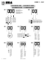 2
2
-
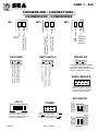 3
3
-
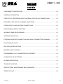 4
4
-
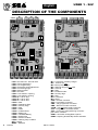 5
5
-
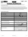 6
6
-
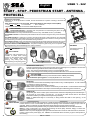 7
7
-
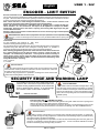 8
8
-
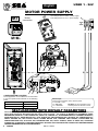 9
9
-
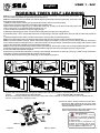 10
10
-
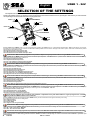 11
11
-
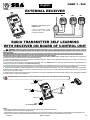 12
12
-
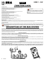 13
13
-
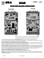 14
14
-
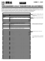 15
15
-
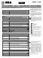 16
16
-
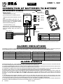 17
17
-
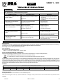 18
18
-
 19
19
-
 20
20
-
 21
21
-
 22
22
-
 23
23
-
 24
24


SEA USER 1 Manuale del proprietario
- Categoria
- Gate Opener
- Tipo
- Manuale del proprietario
- Questo manuale è adatto anche per
in altre lingue
- English: SEA USER 1 Owner's manual
- español: SEA USER 1 El manual del propietario
- Deutsch: SEA USER 1 Bedienungsanleitung
Documenti correlati
-
SEA Unigate FV Manuale utente
-
-
-
-
-
-
-
SEA Slide DG Manuale del proprietario
-
SEA Gate 1 DG R2BF Manuale del proprietario
-
Altri documenti
-
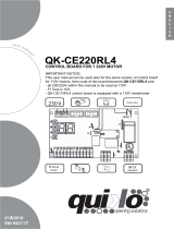 quiko QK-CE220RL4 Manuale utente
-
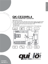 quiko QK-CE220RL4 Manuale utente
-
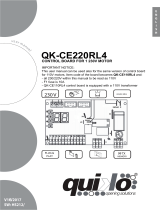 quiko QK-CE220RL4 Manuale utente
-
 quiko QK-CE220BATRL4 Manuale utente
-
 quiko QK-CE220BATRL4 Manuale utente
-
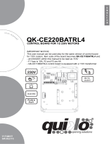 quiko QK-CE220BATRL4 Manuale utente
-
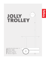 fatboy 346 Manuale utente
-
V2 Elettronica V2 Next Manuale del proprietario
-
Nice Automation TT6 Manuale del proprietario
-
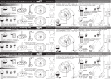 quiko QK-LUX24LED Manuale utente


