Tecnosystemi VR180 very high efficiency ductable static heat recovery unit Manuale del proprietario
- Tipo
- Manuale del proprietario

MANUALE D’USO / USER MANUAL
Tecnosystemi S.p.A. - Società Benefit
www.tecnosystemi.com
via dell’Industria, 2/4 - Z.I. San Giacomo di Veglia
31029 Vittorio Veneto (Treviso) - Italy
Phone +39 0438.500044 Fax +39 0438.501516
Numero Verde 800 904474 (only for Italy)
email: [email protected]
C.F. - P. IVA - R.I.TV IT02535780247 | Cap. Soc. € 5.000.000,00 i.v.
REV. 00 / 09-02-2023
COD. CMU00118
“VR180” RECUPERATORE DI CALORE STATICO
CANALIZZABILE ALTISSIMA EFFICIENZA CON BY-PASS
AUTOMATICO INCLUSO PER INSTALLAZIONE
ORIZZONTALE / VERTICALE / DESTRA / SINISTRA
“VR180” HIGH-EFFICIENCY CEILING-MOUNTED
DUCTABLE STATIC HEAT RECOVERY UNIT WITH
SPEED REGULATOR INCLUDED
• cod. ACC200014

2
GENERALITÀ
GENERAL INFORMATION
Le unità di recupero calore serie “VR” devono essere installate e gestite seguendo le prescrizioni contenute in questo
manuale. La scrupolosa osservanza di queste semplici e fondamentali istruzioni è una premessa necessaria per:
Eliminare o diminuire fermi macchina per guasti o anomalie imprevisti; Aumentare la vita dei componenti e dell’intera
unità; Diminuire i costi di manutenzione.
MACCHINA NON IDONEA AD OPERARE IN AMBIENTE CON ATMOSFERA ESPLOSIVA E IN AMBIENTI CON AGENTI
FORTEMENTE CORROSIVI.
The heat recovery units series “VR” must be installed and operated in accordance with the requirements contained in this
manual. The strict observance of these simple and basic instructions is a prerequisite for:
Eliminate or reduce downtime due to faults or unforeseen anomalies; Increasing the life of the components and the entire
unit; Decrease the costs of maintenance. MACHINE DOES NOT SUITABLE FOR WORK ENVIRONMENT IN WITH EXPLOSIVE
ATMOSPHERE AND IN ENVIRONMENTS
WITH HIGHLY CORROSIVE AGENTS.
4IT
0. GENERALITÀ pag 4
1. SICUREZZA GENERALE 5
2. AVVERTENZA PER IL SOLLEVAMENTO 5
3. AVVERTENZE PER L’INSTALLAZIONE 5
4. AVVERTENZE PER L’USO 5
5. AVVERTENZE DI SICUREZZA PER
LA MANUTENZIONE 5
6. STOCCAGGIO 5
7. ACCANTONAMENTO 5
8. ROTTAMAZIONE 5
9. TABELLA TECNICA DATI GENERALI 6
10. IDENTIFICAZIONE DELLA MACCHINA 8
11. DICHIARAZIONE DI PRESTAZIONE ENERGETICA 10
12. MODALITÀ INSTALLAZIONE 12
0. GENERALITÀ
Le unità di recupero calore serie RDCD25SK(E), RDCD25SKC(E), RDCD25SKH(E) e RDCD25SKHC(E) devono essere in-
stallate e gestite seguendo le prescrizioni contenute in questo manuale. La scrupolosa osservanza di queste semplici
e fondamentali istruzioni è una premessa necessaria per: Eliminare o diminuire fermi macchina per guasti o anomalie
imprevisti; Aumentare la vita dei componenti e dell’intera unità; Diminuire i costi di manutenzione. Per i dati tecnici,
modalità di installazione e quanto riferito alla manutenzione delle unità con scambiatore entalpico, fare riferimento
alla rispettiva versione con scambiatore standard. D’ora in poi, la lettera (E) della versione entalpica è intenzional-
mente esclusa dal presente manuale.
MACCHINA NON IDONEA AD OPERARE IN AMBIENTE CON ATMOSFERA ESPLOSIVA E IN AMBIENTI CON AGENTI
FORTEMENTE CORROSIVI
COMPONENTI DELLA MACCHINA
(Valido per tutte le macchine)
9
10
3
41
43
10
2 85 6
7 7
29
1 Scambiatore
2 Ventilatore
3 Filtro G4
4 Filtro F7 (Optional)
5 Vano scheda elettronica
6 Ingresso alimentazione
7 Sonde di temperatura
8 Antenna Wi-Fi
9 Staffe di fissaggio
10 Scarico condensa
13. VARIAZIONE CONFIGURAZIONE
DA A (STANDARD) A B 16
14. COLLEGAMENTI ELETTRICI 18
15. COLLEGAMENTI IDRAULICI 24
16. COLLEGAMENTI AERAULICI 24
17. VERIFICA DELLA CORRENTE ASSORBITA 24
18. FUNZIONAMENTO ED USO 24
19. MANUTENZIONE ORDINARIA 25
20. PROTEZIONE ANTIGELO 25
21. FREE-COOLING 25
22. SISTEMA DI CONTROLLO 26
23. MESSAGGI DI ERRORE DEL DISPOSITIVO 28
24. MANUTENZIONI E INTERVENTI 29
INDICE GENERALE
COMPONENTI DELLA MACCHINA
/ COMPONENTS OF THE UNIT
4IT
0. GENERALITÀ pag 4
1. SICUREZZA GENERALE 5
2. AVVERTENZA PER IL SOLLEVAMENTO 5
3. AVVERTENZE PER L’INSTALLAZIONE 5
4. AVVERTENZE PER L’USO 5
5. AVVERTENZE DI SICUREZZA PER
LA MANUTENZIONE 5
6. STOCCAGGIO 5
7. ACCANTONAMENTO 5
8. ROTTAMAZIONE 5
9. TABELLA TECNICA DATI GENERALI 6
10. IDENTIFICAZIONE DELLA MACCHINA 8
11. DICHIARAZIONE DI PRESTAZIONE ENERGETICA 10
12. MODALITÀ INSTALLAZIONE 12
0. GENERALITÀ
Le unità di recupero calore serie RDCD25SK(E), RDCD25SKC(E), RDCD25SKH(E) e RDCD25SKHC(E) devono essere in-
stallate e gestite seguendo le prescrizioni contenute in questo manuale. La scrupolosa osservanza di queste semplici
e fondamentali istruzioni è una premessa necessaria per: Eliminare o diminuire fermi macchina per guasti o anomalie
imprevisti; Aumentare la vita dei componenti e dell’intera unità; Diminuire i costi di manutenzione. Per i dati tecnici,
modalità di installazione e quanto riferito alla manutenzione delle unità con scambiatore entalpico, fare riferimento
alla rispettiva versione con scambiatore standard. D’ora in poi, la lettera (E) della versione entalpica è intenzional-
mente esclusa dal presente manuale.
MACCHINA NON IDONEA AD OPERARE IN AMBIENTE CON ATMOSFERA ESPLOSIVA E IN AMBIENTI CON AGENTI
FORTEMENTE CORROSIVI
COMPONENTI DELLA MACCHINA
(Valido per tutte le macchine)
9
10
3
41
43
10
2 85 6
7 7
29
1 Scambiatore
2 Ventilatore
3 Filtro G4
4 Filtro F7 (Optional)
5 Vano scheda elettronica
6 Ingresso alimentazione
7 Sonde di temperatura
8 Antenna Wi-Fi
9 Staffe di fissaggio
10 Scarico condensa
13. VARIAZIONE CONFIGURAZIONE
DA A (STANDARD) A B 16
14. COLLEGAMENTI ELETTRICI 18
15. COLLEGAMENTI IDRAULICI 24
16. COLLEGAMENTI AERAULICI 24
17. VERIFICA DELLA CORRENTE ASSORBITA 24
18. FUNZIONAMENTO ED USO 24
19. MANUTENZIONE ORDINARIA 25
20. PROTEZIONE ANTIGELO 25
21. FREE-COOLING 25
22. SISTEMA DI CONTROLLO 26
23. MESSAGGI DI ERRORE DEL DISPOSITIVO 28
24. MANUTENZIONI E INTERVENTI 29
INDICE GENERALE
32 ENG
0. GENERAL INFORMATION pag 32
1. GENERAL SAFETY 33
2. LIFTING INSTRUCTIONS 33
3. INSTALLATION INSTRUCTION 33
4. INSTRUCTIONS FOR USE 33
5. SAFETY INSTRUCTIONS FOR MAINTENANCE 33
6. STORAGE 33
7. PROVISION 33
8. SCRAPPING 33
9. GENERAL TECHNICAL DATA TABLE 34
10. IDENTIFICATION OF THE MACHINE 36
11. DECLARATION OF ENERGY PERFORMANCE 38
12. MODE OF INSTALLATION 40
0. GENERAL INFORMATION
The heat recovery units series RDCD25SK(E), RDCD25SKC(E), RDCD25SKH(E) e RDCD25SKHC(E) must be installed and
operated in accordance with the require-ments contained in this manual. The strict observance of these simple and
basic instructions is a prerequisite for: Eliminate or reduce downtime due to faults or unforeseen anomalies; Increa-
sing the life of the components and the entire unit; Decrease the costs of maintenance. For technical data, installation
methods and what concerns maintenance of the units with enthalpy exchanger, refer to the respective version with
standard exchanger. From now on, the letter (E) of the enthalpy version is intentionally excluded from this manual.
MACHINE DOES NOT SUITABLE FOR WORK ENVIRONMENT IN WITH EXPLOSIVE ATMOSPHERE AND IN ENVIRONMENTS
WITH HIGHLY CORROSIVE AGENTS.
COMPONENTS OF THE UNIT
(Valid for all units)
9
10
3
41
43
10
2 85 6
7 7
29
1 Heat Exchanger
2 Fan
3 G4 Filter
4 F7 Filter optional
5 PCB compartment
6 Power supply
7 Temperature probe
8 Wi-fi antenna
9 Fixing brackets
10 Condensate drain
13. CONFIGURATION CHANGE
FROM A (STANDARD) TO B 44
14. ELECTRICAL CONNECTIONS 46
15. HYDRAULIC CONNECTIONS 52
16. AERAULIC CONNECTIONS 52
17. VERIFICATION OF CURRENT CONSUMPTION 52
18. OPERATION AND USE 52
19. ROUTINE MAINTENANCE 53
20. DEFROST PROTECTION 53
21. FREE-COOLING 53
22. CONTROL SYSTEM 54
23. DEVICE ERROR MESSAGES 56
24. MAINTENANCE AND OPERATIONS 57
GENERAL INDEX

3
SICUREZZA GENERALE
GENERAL SAFETY
Il costruttore considera la sicurezza e il buon funzionamento del prodotto solo se l’alimentazione del luogo di
installazione e l’impianto elettrico a servizio sono conformi alle norme vigenti e se il prodotto è utilizzato e installato
secondo le norme di seguito descritte.
The manufacturer considers the safety and proper operation of the product only if the electrical system and the electrical
power supply of the place of installation complies with current regulations and if the product is installed and used according
to the rules described below.
AVVERTENZA PER IL SOLLEVAMENTO
LIFTING INSTRUCTIONS
Il collo, sia nella fase di carico che di scarico, dovrà essere sollevato sempre dalla base del prodotto mediante gru o
carrello elevatore con portata adeguata al peso da sostenere, non capovolgere ne posizionarlo sui fianchi e sottoporlo
a urti violenti. Il prodotto è fornito con apposito imballo protettivo che ne garantisce soltanto un riparo da polvere ed
eventuali graffi superficiali, si consiglia di proteggerlo dagli agenti atmosferici. Adottare tutte le precauzioni previste
dalle norme di sicurezza per evitare possibili danni a persone o cose.
The load during both the charging and discharging , should always be lifted from the base of the product by means of a crane
or forklift with adequate capacity to support the weight , do not turn it or place on the sides and submit to strong shock. The
product is supplied with a suitable protective packaging that provides only shelter from dust and scratches the surface, it is
advisable to protect it from the elements. Take all precautions required by safety regulations to avoid possible damage to
persons or property.
AVVERTENZE PER L’INSTALLAZIONE
INSTALLATION INSTRUCTIONS
La messa in opera della macchina, nonché gli appositi collegamenti elettrici e i raccordi alle canalizzazioni dovranno
essere eseguiti da tecnici specializzati nel settore. La macchina necessita inoltre di uno spazio circostante privo di
ostacoli e che ne consenta l’agevole apertura delle portine di ispezione nonché lo spazio sufficiente per l’estrazione
dei filtri e il cablaggio elettrico dei ventilatori. Di seguito viene riportato possibile modalità di staffaggio dell’unità di
recupero calore. Evidenziamo che i punti di ancoraggio ed il dimensionamento delle staffe deve essere effettuato di
volta in volta in relazione della situazione impiantistica ed a un dimensionamento statico e dinamico del sistema.
The installation of the machine, as well as the appropriate electrical connections to ducts and fittings must be performed
by skilled technicians in the industry. The machine also requires a space environment free of obstacles and enabling the
smooth opening of the doors of inspection as well as enough space for the extraction of the filters and the electrical wiring
of the fans. The following is possible modes of fixing of the heat recovery unit . We emphasize that the anchor points and
the dimensioning of the brackets must be made from time to time in respect of the plant situation and dimensioning of the
static and dynamic system.
AVVERTENZE PER L’USO
INSTRUCTION FOR USE
Prima di mettere in funzione la macchina accertarsi che i collegamenti elettrici siano correttamente cablati e lo scarico
condensa sia appositamente collegato, verificare inoltre che non siano stati dimenticati corpi estranei all’interno della
macchina e che eventuali cavi elettrici siano fissati in maniera adeguata. Non aprire le porte di ispezione con organi in
movimento ne introdurre le mani con la macchina in funzione, come segnalato dagli appositi pittogrammi.

4
Before operating the machine, make sure that the electrical connections are correctly wired and the condensate drain is
specially connected, check to make sure no foreign objects have been left inside the machine and that any electrical cords
are fixed adequately. Do not open the inspection doors with moving parts or introduce hands with the machine running , as
indicated by appropriate pictograms.
AVVERTENZE DI SICUREZZA PER LA MANUTENZIONE
SAFETY INSTRUCTIONS FOR MAINTENANCE
Prima di qualsiasi intervento di manutenzione assicurarsi che la macchina sia scollegata dall’alimentazione elettrica.
Il prodotto è realizzato in modo da facilitare gli interventi di manutenzione che devono essere effettuati da personale
qualificato. Qualora venissero effettuati interventi di riparazione o manutenzione straordinaria rivolgersi alla ditta
costruttrice che provvederà a farli eseguire da personale autorizzato o darà il consenso per poterlo far effettuare da
altro personale professionalmente qualificato. Per qualsiasi altro problema, dubbio o anomalia prima di procedere
con operazioni che possono risultare dannose o scorrette alla macchina contattare l’ufficio assistenza tecnica il quale
provvederà a fornire tutte le indicazioni necessarie per riuscire a risolvere, se possibile, il caso.
Before performing any maintenance make sure that the machine is disconnected from the power supply. The product is
made in order to facilitate maintenance operations that allow it to be carried out by qualified personnel. Where were carried
out repairs or extraordinary maintenance, please contact the constructor that will have them done by authorized personnel
or give consent to be able to be performed by other qualified personnel. For any other problem, doubt or anomaly before
proceeding with operations that can be harmful to the machine or incorrect, contact the service office which will provide all
the necessary information to be able to solve, if possible, the case.
STOCCAGGIO
STORAGE
È consentito lo stoccaggio della macchina per un lungo periodo purchè il luogo sia asciutto, al riparo da sole e
comunque ad una temperatura compresa tra 0 e 40°C, al riparo da pioggia e umidità, consigliamo di mantenere
intatto l’imballo e appoggiare la macchina su pallet o scaffalature.
Permitted storage of the machine for a long time as long as the place is dry , protected from the sun and at a temperature
between 0 and 40 ° C, protected from rain and humidity , maybe suggest to keep the packaging intact and support the
machine on pallets or shelves.
ACCANTONAMENTO
PROVISIONS
Non è possibile accantonare la macchina.
You cannot set aside the machine.
ROTTAMAZIONE
SCRAPPING
Nel caso si decidesse di non utilizzare più questo articolo si raccomanda di scollegare l’alimentazione elettrica,
disassemblare tutti i vari componenti e smaltire l’articolo conformemente alle normative locali in materia in modo da
rispettare le normative in vigore al fine di rispettare l’ambiente.
If you decide not to use this product it is recommended to disconnect the power supply, disassemble and dispose of all the various
components of the item in accordance with the relevant local regulations in order to comply with the regulations in force in order
to respect the environment.

5
TABELLA DATI TECNICI GENERALI / GENERAL TECHNICAL DATA TABLE
Portata aria / Nominal air flow [mc/h] 180
Pressione statica utile / Useful static pressure [Pa] 100
DATI PER SINGOLO VENTILATORE / DATA FOR EACH FAN
Potenza nominale / Rated power [W] 27
Giri / Round [1/min] 3700
I nominale / Current [A] 0,27
Tensione / Rated voltage [V] 230
Frequenza / Frequency [Hz] 50
FILTRI / FILTERS
Efficienza Standard / Efficiency Standard G4
Efficienza Optional / Efficiency Optional F7
Vista da sotto / Bottom view Vista frontale / Front view
6IT
FILTRO G4
G4 FILTER EFFICIENCY
FILTRO F7 (OPZIONAL)
F7 FILTER EFFICIENCY (OPTIONAL)
SCARICO CONDENSA
CONDENSATE DRAIN
1005
580 648
STAFFE ASOLATE Ø10
BRACKET WITH SLOTS Ø10
52
Ø156
609
617
268
320
130
130
900
FILTRO G4
G4 FILTER EFFICIENCY
FILTRO F7 (OPZIONAL)
F7 FILTER EFFICIENCY (OPTIONAL)
SCARICO CONDENSA
CONDENSATE DRAIN
1005
580 648
STAFFE ASOLATE Ø10
BRACKET WITH SLOTS Ø10
52
Ø156
609
617
268
320
130
130
900
(Valido per RDCD25SK e RDCD25SKH)
RDCD25SK RDCD25SKH
Portata aria (mc/h) 180 250
Pressione statica utile (pa) 100 100
DATI PER SINGOLO VENTILATORE
Potenza nominale (w) 27 50
Giri (1/min) 3700 4320
I nominale (A) 0,27 0,46
Tensione (V) 230 230
Frequenza (Hz) 50 50
Velocità (nr) 1 1
FILTRI
Efficienza Standard G4 G4
Efficienza Optional F7 F7
PESO: 14 kg
Vista in piana
Vista da sotto
Vista laterale
Vista frontale
9. TABELLA TECNICA DATI GENERALI
Vista laterale / Side view
Vista in piana / Plan view
PESO: 14 kg
/ WEIGHT: 14 kg
IDENTIFICAZIONE DELLA MACCHINA
IDENTIFICATION OF THE MACHINE
Ogni unità è provvista di una targhetta identificativa che contiene i principali dati della macchina. È necessario, per
ogni rapporto con il costruttore, citare sempre tipo e/o numero di serie indicati su questa targa.
Each unit is equipped with a identification plate that contains important data on the machine.
It is necessary for any relationship with the constructor, always quote the type and / or serial number shown on this plate.

6
DICHIARAZIONE DI PRESTAZIONE
DELL’UNITA DI RECUPERO DEL CALORE
DECLARATION OF PERFORMANCE HEAT RECOVERY UNIT
Clima di riferimento / Reference climate Temperato
/ Average
Freddo
/ Cold
Caldo
/ Hot
SEC in [kWh/(m²a)] per ogni tipo di clima (temperato,
caldo, freddo)/ -35,83 -76,93 -12,92
SEC Class A A+ E
Tipologia dichiarata dell’unità di ventilazione UVR-B Bidirezionale / UVR-B Bidirectional
Tipo di azionamento installato Azionamento a velocità multiple / Multi-speed drive
Tipo di sistema di recupero del calore A recupero / Recuperative
Efficienza termica ¹ 81,1%
Portata massima in [m³/h] ² 180
Potenza elettrica complessiva massima portata [W] 60
Livello di potenza sonora (LWA) in [dB(A)] ³ 46
Portata di riferimento in [m3/h]
4
126
Differenze di pressione di riferimento [Pa] 50
SPI in [W/m³/h]
5
0,21
Fattore di controllo e tipologia 1
Percentuale massima di trafilamento interno [%]
6
1,2
Percentuale massima di trafilamento esterno [%]
6
2,5
9
IT
ENERGIA ЕНЕРГИЯ ΕΝΕΡΓΕΙΑ ENERGIJA ENERGY ENERGIE ENERGI
2016 1254/2014
A
A
A
B
dB
C
D
E
F
G
m18046 ³/h
RDCD25SK
ENERGIA ЕНЕРГИЯ ΕΝΕΡΓΕΙΑ ENERGIJA ENERGY ENERGIE ENERGI
2016 1254/2014
A
A
A
B
dB
C
D
E
F
G
m18039 ³/h
RDCD25SKC
ENERGIA ЕНЕРГИЯ ΕΝΕΡΓΕΙΑ ENERGIJA ENERGY ENERGIE ENERGI
2016 1254/2014
A
A
A
B
dB
C
D
E
F
G
m25050 ³/h
RDCD25SKH
ENERGIA ЕНЕРГИЯ ΕΝΕΡΓΕΙΑ ENERGIJA ENERGY ENERGIE ENERGI
2016 1254/2014
A
A
A
B
dB
C
D
E
F
G
m25044 ³/h
RDCD25SKHC

7
INSTALLAZIONE VERTICALE A PARETE
VERTICAL WALL INSTALLATION
12 IT
FA
R
FAEX
S
FILTER
FILTER
ENERGIA ЕНЕРГИЯ ΕΝΕΡΓΕΙΑ ENERGIJA ENERGY ENERGIE ENERGI
2016 1254/2014
A
A
A
B
46
dB
C
D
E
F
G
260 m³/h
RDCD25SK
EX
R
SFA
FILTER
FILTER
ENERGIA ЕНЕРГИЯ ΕΝΕΡΓΕΙΑ ENERGIJA ENERGY ENERGIE ENERGI
2016 1254/2014
A
A
A
B
46
dB
C
D
E
F
G
260 m³/h
RDCD25SK
EX
R
S
R
FILTER
FILTER
ENERGIA ЕНЕРГИЯ ΕΝΕΡΓΕΙΑ ENERGIJA ENERGY ENERGIE ENERGI
2016 1254/2014
A
A
A
B
46
dB
C
D
E
F
G
260 m³/h
RDCD25SK
S
FA
EX R
FILTER
FILTER
ENERGIA ЕНЕРГИЯ ΕΝΕΡΓΕΙΑ ENERGIJA ENERGY ENERGIE ENERGI
2016 1254/2014
A
A
A
B
46
dB
C
D
E
F
G
260 m³/h
RDCD25SK
S
FA
EX
making air better
making air better
making air better
making air better
R
FA EX
S
FILTER
FILTER
ENERGIA ЕНЕРГИЯ ΕΝΕΡΓΕΙΑ ENERGIJA ENERGY ENERGIE ENERGI
2016 1254/2014
A
A
A
B
46
dB
C
D
E
F
G
260 m³/h
RDCD25SK
making air better
ISPEZIONE
FILTRI
CHECK
FI
LTER
ISPEZIONE
FILTRI
CHECK
FILTER
FILTER
FILTER
ENERGIA ЕНЕРГИЯ ΕΝΕΡΓΕΙΑ ENERGIJA ENERGY ENERGIE ENERGI
2016 1254/2014
A
A
A
B
46
dB
C
D
E
F
G
260 m³/h
RDCD25SK
ISPEZIONE
FILTRI
CHECK
FI
L
TER
ISPEZIONE
FILTRI
CHECK
FI
L
TER
making air better
ISPEZIONE
FILTRI
CHECK
FILTER
ISPEZIONE
FILTRI
CHECK
FILTER
ISPEZIONE
FILTRI
CHECK
FILTER
ISPEZIONE
FILTRI
CHECK
FILTER
ISPEZIONE
FILTRI
CHECK
FILTER
ISPEZIONE
FILTRI
CHECK
FILTER
ISPEZIONE
FILTRI
CHECK
FILTER
ISPEZIONE
FILTRI
CHECK
FILTER
FA
R
FAEX
S
FILTER
FILTER
ENERGIA ЕНЕРГИЯ ΕΝΕΡΓΕΙΑ ENERGIJA ENERGY ENERGIE ENERGI
2016 1254/2014
A
A
A
B
46
dB
C
D
E
F
G
260 m³/h
RDCD25SK
EX
R
SFA
FILTER
FILTER
ENERGIA ЕНЕРГИЯ ΕΝΕΡΓΕΙΑ ENERGIJA ENERGY ENERGIE ENERGI
2016 1254/2014
A
A
A
B
46
dB
C
D
E
F
G
260 m³/h
RDCD25SK
EX
R
S
R
FILTER
FILTER
ENERGIA ЕНЕРГИЯ ΕΝΕΡΓΕΙΑ ENERGIJA ENERGY ENERGIE ENERGI
2016 1254/2014
A
A
A
B
46
dB
C
D
E
F
G
260 m³/h
RDCD25SK
S
FA
EX R
FILTER
FILTER
ENERGIA ЕНЕРГИЯ ΕΝΕΡΓΕΙΑ ENERGIJA ENERGY ENERGIE ENERGI
2016 1254/2014
A
A
A
B
46
dB
C
D
E
F
G
260 m³/h
RDCD25SK
S
FA
EX
making air better
making air better
making air better
making air better
R
FA EX
S
FILTER
FILTER
ENERGIA ЕНЕРГИЯ ΕΝΕΡΓΕΙΑ ENERGIJA ENERGY ENERGIE ENERGI
2016 1254/2014
A
A
A
B
46
dB
C
D
E
F
G
260 m³/h
RDCD25SK
making air better
ISPEZIONE
FILTRI
CHECK
FILTER
ISPEZIONE
FILTRI
CHECK
FILTER
FILTER
FILTER
ENERGIA ЕНЕРГИЯ ΕΝΕΡΓΕΙΑ ENERGIJA ENERGY ENERGIE ENERGI
2016 1254/2014
A
A
A
B
46
dB
C
D
E
F
G
260 m³/h
RDCD25SK
ISPEZIONE
FILTRI
CHECK
FILTER
ISPEZIONE
FILTRI
CHECK
FILTER
making air better
ISPEZIONE
FILTRI
CHECK
FILTER
ISPEZIONE
FILTRI
CHECK
FI
LTER
ISPEZIONE
FILTRI
CHECK
FILTER
ISPEZIONE
FILTRI
CHECK
FILTER
ISPEZIONE
FILTRI
CHECK
FILTER
ISPEZIONE
FILTRI
CHECK
FILTER
ISPEZIONE
FILTRI
CHECK
FILTER
ISPEZIONE
FILTRI
CHECK
FI
LTER
FA
R
FAEX
S
FILTER
FILTER
ENERGIA ЕНЕРГИЯ ΕΝΕΡΓΕΙΑ ENERGIJA ENERGY ENERGIE ENERGI
2016 1254/2014
A
A
A
B
46
dB
C
D
E
F
G
260 m³/h
RDCD25SK
EX
R
SFA
FILTER
FILTER
ENERGIA ЕНЕРГИЯ ΕΝΕΡΓΕΙΑ ENERGIJA ENERGY ENERGIE ENERGI
2016 1254/2014
A
A
A
B
46
dB
C
D
E
F
G
260 m³/h
RDCD25SK
EX
R
S
R
FILTER
FILTER
ENERGIA ЕНЕРГИЯ ΕΝΕΡΓΕΙΑ ENERGIJA ENERGY ENERGIE ENERGI
2016 1254/2014
A
A
A
B
46
dB
C
D
E
F
G
260 m³/h
RDCD25SK
S
FA
EX R
FILTER
FILTER
ENERGIA ЕНЕРГИЯ ΕΝΕΡΓΕΙΑ ENERGIJA ENERGY ENERGIE ENERGI
2016 1254/2014
A
A
A
B
46
dB
C
D
E
F
G
260 m³/h
RDCD25SK
S
FA
EX
making air better
making air better
making air better
making air better
R
FA EX
S
FILTER
FILTER
ENERGIA ЕНЕРГИЯ ΕΝΕΡΓΕΙΑ ENERGIJA ENERGY ENERGIE ENERGI
2016 1254/2014
A
A
A
B
46
dB
C
D
E
F
G
260 m³/h
RDCD25SK
making air better
ISPEZIONE
FILTRI
CHECK
FILTER
ISPEZIONE
FILTRI
CHECK
FILTER
FILTER
FILTER
ENERGIA ЕНЕРГИЯ ΕΝΕΡΓΕΙΑ ENERGIJA ENERGY ENERGIE ENERGI
2016 1254/2014
A
A
A
B
46
dB
C
D
E
F
G
260 m³/h
RDCD25SK
ISPEZIONE
FILTRI
CHECK
FILTER
ISPEZIONE
FILTRI
CHECK
FILTER
making air better
ISPEZIONE
FILTRI
CHECK
FILTER
ISPEZIONE
FILTRI
CHECK
FILTER
ISPEZIONE
FILTRI
CHECK
FI
L
TER
ISPEZIONE
FILTRI
CHECK
FIL
TER
ISPEZIONE
FILTRI
CHECK
FILTER
ISPEZIONE
FILTRI
CHECK
FI
LTER
ISPEZIONE
FILTRI
CHECK
FILTER
ISPEZIONE
FILTRI
CHECK
FILTER
INSTALLAZIONE VERTICALE A PARETE
Tipo A (Standard) Tipo B
INSTALLAZIONE ORIZZONTALE A SOFFITTO
Tipo - A (Standard)
Tipo - B
Tipo - A1 (Standard)
Tipo - B1
RDCD25SK e RDCD25SKH
12. MODALITÀ INSTALLAZIONE
Leggenda
EX = espulsione
R = ripresa
FA = aria esterna
S = mandata
40 ENG
FA
R
FAEX
S
FILTER
FILTER
ENERGIA ЕНЕРГИЯ ΕΝΕΡΓΕΙΑ ENERGIJA ENERGY ENERGIE ENERGI
2016 1254/2014
A
A
A
B
46
dB
C
D
E
F
G
260 m³/h
RDCD25SK
EX
R
SFA
FILTER
FILTER
ENERGIA ЕНЕРГИЯ ΕΝΕΡΓΕΙΑ ENERGIJA ENERGY ENERGIE ENERGI
2016 1254/2014
A
A
A
B
46
dB
C
D
E
F
G
260 m³/h
RDCD25SK
EX
R
S
R
FILTER
FILTER
ENERGIA ЕНЕРГИЯ ΕΝΕΡΓΕΙΑ ENERGIJA ENERGY ENERGIE ENERGI
2016 1254/2014
A
A
A
B
46
dB
C
D
E
F
G
260 m³/h
RDCD25SK
S
FA
EX R
FILTER
FILTER
ENERGIA ЕНЕРГИЯ ΕΝΕΡΓΕΙΑ ENERGIJA ENERGY ENERGIE ENERGI
2016 1254/2014
A
A
A
B
46
dB
C
D
E
F
G
260 m³/h
RDCD25SK
S
FA
EX
making air better
making air better
making air better
making air better
R
FA EX
S
FILTER
FILTER
ENERGIA ЕНЕРГИЯ ΕΝΕΡΓΕΙΑ ENERGIJA ENERGY ENERGIE ENERGI
2016 1254/2014
A
A
A
B
46
dB
C
D
E
F
G
260 m³/h
RDCD25SK
making air better
ISPEZIONE
FILTRI
CHECK
FI
LTER
ISPEZIONE
FILTRI
CHECK
FILTER
FILTER
FILTER
ENERGIA ЕНЕРГИЯ ΕΝΕΡΓΕΙΑ ENERGIJA ENERGY ENERGIE ENERGI
2016 1254/2014
A
A
A
B
46
dB
C
D
E
F
G
260 m³/h
RDCD25SK
ISPEZIONE
FILTRI
CHECK
FI
L
TER
ISPEZIONE
FILTRI
CHECK
FI
L
TER
making air better
ISPEZIONE
FILTRI
CHECK
FILTER
ISPEZIONE
FILTRI
CHECK
FILTER
ISPEZIONE
FILTRI
CHECK
FILTER
ISPEZIONE
FILTRI
CHECK
FILTER
ISPEZIONE
FILTRI
CHECK
FILTER
ISPEZIONE
FILTRI
CHECK
FILTER
ISPEZIONE
FILTRI
CHECK
FILTER
ISPEZIONE
FILTRI
CHECK
FILTER
FA
R
FAEX
S
FILTER
FILTER
ENERGIA ЕНЕРГИЯ ΕΝΕΡΓΕΙΑ ENERGIJA ENERGY ENERGIE ENERGI
2016 1254/2014
A
A
A
B
46
dB
C
D
E
F
G
260 m³/h
RDCD25SK
EX
R
SFA
FILTER
FILTER
ENERGIA ЕНЕРГИЯ ΕΝΕΡΓΕΙΑ ENERGIJA ENERGY ENERGIE ENERGI
2016 1254/2014
A
A
A
B
46
dB
C
D
E
F
G
260 m³/h
RDCD25SK
EX
R
S
R
FILTER
FILTER
ENERGIA ЕНЕРГИЯ ΕΝΕΡΓΕΙΑ ENERGIJA ENERGY ENERGIE ENERGI
2016 1254/2014
A
A
A
B
46
dB
C
D
E
F
G
260 m³/h
RDCD25SK
S
FA
EX R
FILTER
FILTER
ENERGIA ЕНЕРГИЯ ΕΝΕΡΓΕΙΑ ENERGIJA ENERGY ENERGIE ENERGI
2016 1254/2014
A
A
A
B
46
dB
C
D
E
F
G
260 m³/h
RDCD25SK
S
FA
EX
making air better
making air better
making air better
making air better
R
FA EX
S
FILTER
FILTER
ENERGIA ЕНЕРГИЯ ΕΝΕΡΓΕΙΑ ENERGIJA ENERGY ENERGIE ENERGI
2016 1254/2014
A
A
A
B
46
dB
C
D
E
F
G
260 m³/h
RDCD25SK
making air better
ISPEZIONE
FILTRI
CHECK
FILTER
ISPEZIONE
FILTRI
CHECK
FILTER
FILTER
FILTER
ENERGIA ЕНЕРГИЯ ΕΝΕΡΓΕΙΑ ENERGIJA ENERGY ENERGIE ENERGI
2016 1254/2014
A
A
A
B
46
dB
C
D
E
F
G
260 m³/h
RDCD25SK
ISPEZIONE
FILTRI
CHECK
FILTER
ISPEZIONE
FILTRI
CHECK
FILTER
making air better
ISPEZIONE
FILTRI
CHECK
FILTER
ISPEZIONE
FILTRI
CHECK
FI
LTER
ISPEZIONE
FILTRI
CHECK
FILTER
ISPEZIONE
FILTRI
CHECK
FILTER
ISPEZIONE
FILTRI
CHECK
FILTER
ISPEZIONE
FILTRI
CHECK
FILTER
ISPEZIONE
FILTRI
CHECK
FILTER
ISPEZIONE
FILTRI
CHECK
FI
LTER
FA
R
FAEX
S
FILTER
FILTER
ENERGIA ЕНЕРГИЯ ΕΝΕΡΓΕΙΑ ENERGIJA ENERGY ENERGIE ENERGI
2016 1254/2014
A
A
A
B
46
dB
C
D
E
F
G
260 m³/h
RDCD25SK
EX
R
SFA
FILTER
FILTER
ENERGIA ЕНЕРГИЯ ΕΝΕΡΓΕΙΑ ENERGIJA ENERGY ENERGIE ENERGI
2016 1254/2014
A
A
A
B
46
dB
C
D
E
F
G
260 m³/h
RDCD25SK
EX
R
S
R
FILTER
FILTER
ENERGIA ЕНЕРГИЯ ΕΝΕΡΓΕΙΑ ENERGIJA ENERGY ENERGIE ENERGI
2016 1254/2014
A
A
A
B
46
dB
C
D
E
F
G
260 m³/h
RDCD25SK
S
FA
EX R
FILTER
FILTER
ENERGIA ЕНЕРГИЯ ΕΝΕΡΓΕΙΑ ENERGIJA ENERGY ENERGIE ENERGI
2016 1254/2014
A
A
A
B
46
dB
C
D
E
F
G
260 m³/h
RDCD25SK
S
FA
EX
making air better
making air better
making air better
making air better
R
FA EX
S
FILTER
FILTER
ENERGIA ЕНЕРГИЯ ΕΝΕΡΓΕΙΑ ENERGIJA ENERGY ENERGIE ENERGI
2016 1254/2014
A
A
A
B
46
dB
C
D
E
F
G
260 m³/h
RDCD25SK
making air better
ISPEZIONE
FILTRI
CHECK
FILTER
ISPEZIONE
FILTRI
CHECK
FILTER
FILTER
FILTER
ENERGIA ЕНЕРГИЯ ΕΝΕΡΓΕΙΑ ENERGIJA ENERGY ENERGIE ENERGI
2016 1254/2014
A
A
A
B
46
dB
C
D
E
F
G
260 m³/h
RDCD25SK
ISPEZIONE
FILTRI
CHECK
FILTER
ISPEZIONE
FILTRI
CHECK
FILTER
making air better
ISPEZIONE
FILTRI
CHECK
FILTER
ISPEZIONE
FILTRI
CHECK
FILTER
ISPEZIONE
FILTRI
CHECK
FI
L
TER
ISPEZIONE
FILTRI
CHECK
FIL
TER
ISPEZIONE
FILTRI
CHECK
FILTER
ISPEZIONE
FILTRI
CHECK
FI
LTER
ISPEZIONE
FILTRI
CHECK
FILTER
ISPEZIONE
FILTRI
CHECK
FILTER
VERTICAL WALL INSTALLATION
Type A (Standard) Type B
HORIZZONTAL CEILING INSTALLATION
Type - A (Standard)
Type - B
Type - A1 (Standard)
Type - B1
RDCD25SK and RDCD25SKH
12. MODE OF INSTALLATION
Legend
EX =
exhaust air
R =
return
FA =
fresh air
S =
supply
INSTALLAZIONE ORIZZONTALE A SOFFITTO
HORIZZONTAL CEILING INSTALLATION
12 IT
FA
R
FAEX
S
FILTER
FILTER
ENERGIA ЕНЕРГИЯ ΕΝΕΡΓΕΙΑ ENERGIJA ENERGY ENERGIE ENERGI
2016 1254/2014
A
A
A
B
46
dB
C
D
E
F
G
260 m³/h
RDCD25SK
EX
R
SFA
FILTER
FILTER
ENERGIA ЕНЕРГИЯ ΕΝΕΡΓΕΙΑ ENERGIJA ENERGY ENERGIE ENERGI
2016 1254/2014
A
A
A
B
46
dB
C
D
E
F
G
260 m³/h
RDCD25SK
EX
R
S
R
FILTER
FILTER
ENERGIA ЕНЕРГИЯ ΕΝΕΡΓΕΙΑ ENERGIJA ENERGY ENERGIE ENERGI
2016 1254/2014
A
A
A
B
46
dB
C
D
E
F
G
260 m³/h
RDCD25SK
S
FA
EX R
FILTER
FILTER
ENERGIA ЕНЕРГИЯ ΕΝΕΡΓΕΙΑ ENERGIJA ENERGY ENERGIE ENERGI
2016 1254/2014
A
A
A
B
46
dB
C
D
E
F
G
260 m³/h
RDCD25SK
S
FA
EX
making air better
making air better
making air better
making air better
R
FA EX
S
FILTER
FILTER
ENERGIA ЕНЕРГИЯ ΕΝΕΡΓΕΙΑ ENERGIJA ENERGY ENERGIE ENERGI
2016 1254/2014
A
A
A
B
46
dB
C
D
E
F
G
260 m³/h
RDCD25SK
making air better
ISPEZIONE
FILTRI
CHECK
FI
LTER
ISPEZIONE
FILTRI
CHECK
FILTER
FILTER
FILTER
ENERGIA ЕНЕРГИЯ ΕΝΕΡΓΕΙΑ ENERGIJA ENERGY ENERGIE ENERGI
2016 1254/2014
A
A
A
B
46
dB
C
D
E
F
G
260 m³/h
RDCD25SK
ISPEZIONE
FILTRI
CHECK
FILTER
ISPEZIONE
FILTRI
CHECK
FI
LTER
making air better
ISPEZIONE
FILTRI
CHECK
FILTER
ISPEZIONE
FILTRI
CHECK
FILTER
ISPEZIONE
FILTRI
CHECK
FILTER
ISPEZIONE
FILTRI
CHECK
FILTER
ISPEZIONE
FILTRI
CHECK
FILTER
ISPEZIONE
FILTRI
CHECK
FILTER
ISPEZIONE
FILTRI
CHECK
FILTER
ISPEZIONE
FILTRI
CHECK
FILTER
FA
R
FAEX
S
FILTER
FILTER
ENERGIA ЕНЕРГИЯ ΕΝΕΡΓΕΙΑ ENERGIJA ENERGY ENERGIE ENERGI
2016 1254/2014
A
A
A
B
46
dB
C
D
E
F
G
260 m³/h
RDCD25SK
EX
R
SFA
FILTER
FILTER
ENERGIA ЕНЕРГИЯ ΕΝΕΡΓΕΙΑ ENERGIJA ENERGY ENERGIE ENERGI
2016 1254/2014
A
A
A
B
46
dB
C
D
E
F
G
260 m³/h
RDCD25SK
EX
R
S
R
FILTER
FILTER
ENERGIA ЕНЕРГИЯ ΕΝΕΡΓΕΙΑ ENERGIJA ENERGY ENERGIE ENERGI
2016 1254/2014
A
A
A
B
46
dB
C
D
E
F
G
260 m³/h
RDCD25SK
S
FA
EX R
FILTER
FILTER
ENERGIA ЕНЕРГИЯ ΕΝΕΡΓΕΙΑ ENERGIJA ENERGY ENERGIE ENERGI
2016 1254/2014
A
A
A
B
46
dB
C
D
E
F
G
260 m³/h
RDCD25SK
S
FA
EX
making air better
making air better
making air better
making air better
R
FA EX
S
FILTER
FILTER
ENERGIA ЕНЕРГИЯ ΕΝΕΡΓΕΙΑ ENERGIJA ENERGY ENERGIE ENERGI
2016 1254/2014
A
A
A
B
46
dB
C
D
E
F
G
260 m³/h
RDCD25SK
making air better
ISPEZIONE
FILTRI
CHECK
FILTER
ISPEZIONE
FILTRI
CHECK
FILTER
FILTER
FILTER
ENERGIA ЕНЕРГИЯ ΕΝΕΡΓΕΙΑ ENERGIJA ENERGY ENERGIE ENERGI
2016 1254/2014
A
A
A
B
46
dB
C
D
E
F
G
260 m³/h
RDCD25SK
ISPEZIONE
FILTRI
CHECK
FILTER
ISPEZIONE
FILTRI
CHECK
FILTER
making air better
ISPEZIONE
FILTRI
CHECK
FILTER
ISPEZIONE
FILTRI
CHECK
FI
LTER
ISPEZIONE
FILTRI
CHECK
FILTER
ISPEZIONE
FILTRI
CHECK
FILTER
ISPEZIONE
FILTRI
CHECK
FILTER
ISPEZIONE
FILTRI
CHECK
FILTER
ISPEZIONE
FILTRI
CHECK
FILTER
ISPEZIONE
FILTRI
CHECK
FI
LTER
FA
R
FAEX
S
FILTER
FILTER
ENERGIA ЕНЕРГИЯ ΕΝΕΡΓΕΙΑ ENERGIJA ENERGY ENERGIE ENERGI
2016 1254/2014
A
A
A
B
46
dB
C
D
E
F
G
260 m³/h
RDCD25SK
EX
R
SFA
FILTER
FILTER
ENERGIA ЕНЕРГИЯ ΕΝΕΡΓΕΙΑ ENERGIJA ENERGY ENERGIE ENERGI
2016 1254/2014
A
A
A
B
46
dB
C
D
E
F
G
260 m³/h
RDCD25SK
EX
R
S
R
FILTER
FILTER
ENERGIA ЕНЕРГИЯ ΕΝΕΡΓΕΙΑ ENERGIJA ENERGY ENERGIE ENERGI
2016 1254/2014
A
A
A
B
46
dB
C
D
E
F
G
260 m³/h
RDCD25SK
S
FA
EX R
FILTER
FILTER
ENERGIA ЕНЕРГИЯ ΕΝΕΡΓΕΙΑ ENERGIJA ENERGY ENERGIE ENERGI
2016 1254/2014
A
A
A
B
46
dB
C
D
E
F
G
260 m³/h
RDCD25SK
S
FA
EX
making air better
making air better
making air better
making air better
R
FA EX
S
FILTER
FILTER
ENERGIA ЕНЕРГИЯ ΕΝΕΡΓΕΙΑ ENERGIJA ENERGY ENERGIE ENERGI
2016 1254/2014
A
A
A
B
46
dB
C
D
E
F
G
260 m³/h
RDCD25SK
making air better
ISPEZIONE
FILTRI
CHECK
FILTER
ISPEZIONE
FILTRI
CHECK
FILTER
FILTER
FILTER
ENERGIA ЕНЕРГИЯ ΕΝΕΡΓΕΙΑ ENERGIJA ENERGY ENERGIE ENERGI
2016 1254/2014
A
A
A
B
46
dB
C
D
E
F
G
260 m³/h
RDCD25SK
ISPEZIONE
FILTRI
CHECK
FILTER
ISPEZIONE
FILTRI
CHECK
FILTER
making air better
ISPEZIONE
FILTRI
CHECK
FILTER
ISPEZIONE
FILTRI
CHECK
FILTER
ISPEZIONE
FILTRI
CHECK
FI
L
TER
ISPEZIONE
FILTRI
CHECK
FIL
TER
ISPEZIONE
FILTRI
CHECK
FILTER
ISPEZIONE
FILTRI
CHECK
FI
LTER
ISPEZIONE
FILTRI
CHECK
FILTER
ISPEZIONE
FILTRI
CHECK
FILTER
INSTALLAZIONE VERTICALE A PARETE
Tipo A (Standard) Tipo B
INSTALLAZIONE ORIZZONTALE A SOFFITTO
Tipo - A (Standard)
Tipo - B
Tipo - A1 (Standard)
Tipo - B1
RDCD25SK e RDCD25SKH
12. MODALITÀ INSTALLAZIONE
Leggenda
EX = espulsione
R = ripresa
FA = aria esterna
S = mandata
12 IT
FA
R
FAEX
S
FILTER
FILTER
ENERGIA ЕНЕРГИЯ ΕΝΕΡΓΕΙΑ ENERGIJA ENERGY ENERGIE ENERGI
2016 1254/2014
A
A
A
B
46
dB
C
D
E
F
G
260 m³/h
RDCD25SK
EX
R
SFA
FILTER
FILTER
ENERGIA ЕНЕРГИЯ ΕΝΕΡΓΕΙΑ ENERGIJA ENERGY ENERGIE ENERGI
2016 1254/2014
A
A
A
B
46
dB
C
D
E
F
G
260 m³/h
RDCD25SK
EX
R
S
R
FILTER
FILTER
ENERGIA ЕНЕРГИЯ ΕΝΕΡΓΕΙΑ ENERGIJA ENERGY ENERGIE ENERGI
2016 1254/2014
A
A
A
B
46
dB
C
D
E
F
G
260 m³/h
RDCD25SK
S
FA
EX R
FILTER
FILTER
ENERGIA ЕНЕРГИЯ ΕΝΕΡΓΕΙΑ ENERGIJA ENERGY ENERGIE ENERGI
2016 1254/2014
A
A
A
B
46
dB
C
D
E
F
G
260 m³/h
RDCD25SK
S
FA
EX
making air better
making air better
making air better
making air better
R
FA EX
S
FILTER
FILTER
ENERGIA ЕНЕРГИЯ ΕΝΕΡΓΕΙΑ ENERGIJA ENERGY ENERGIE ENERGI
2016 1254/2014
A
A
A
B
46
dB
C
D
E
F
G
260 m³/h
RDCD25SK
making air better
ISPEZIONE
FILTRI
CHECK
FI
LTER
ISPEZIONE
FILTRI
CHECK
FILTER
FILTER
FILTER
ENERGIA ЕНЕРГИЯ ΕΝΕΡΓΕΙΑ ENERGIJA ENERGY ENERGIE ENERGI
2016 1254/2014
A
A
A
B
46
dB
C
D
E
F
G
260 m³/h
RDCD25SK
ISPEZIONE
FILTRI
CHECK
FI
L
TER
ISPEZIONE
FILTRI
CHECK
FI
L
TER
making air better
ISPEZIONE
FILTRI
CHECK
FILTER
ISPEZIONE
FILTRI
CHECK
FILTER
ISPEZIONE
FILTRI
CHECK
FILTER
ISPEZIONE
FILTRI
CHECK
FILTER
ISPEZIONE
FILTRI
CHECK
FILTER
ISPEZIONE
FILTRI
CHECK
FILTER
ISPEZIONE
FILTRI
CHECK
FILTER
ISPEZIONE
FILTRI
CHECK
FILTER
FA
R
FAEX
S
FILTER
FILTER
ENERGIA ЕНЕРГИЯ ΕΝΕΡΓΕΙΑ ENERGIJA ENERGY ENERGIE ENERGI
2016 1254/2014
A
A
A
B
46
dB
C
D
E
F
G
260 m³/h
RDCD25SK
EX
R
SFA
FILTER
FILTER
ENERGIA ЕНЕРГИЯ ΕΝΕΡΓΕΙΑ ENERGIJA ENERGY ENERGIE ENERGI
2016 1254/2014
A
A
A
B
46
dB
C
D
E
F
G
260 m³/h
RDCD25SK
EX
R
S
R
FILTER
FILTER
ENERGIA ЕНЕРГИЯ ΕΝΕΡΓΕΙΑ ENERGIJA ENERGY ENERGIE ENERGI
2016 1254/2014
A
A
A
B
46
dB
C
D
E
F
G
260 m³/h
RDCD25SK
S
FA
EX R
FILTER
FILTER
ENERGIA ЕНЕРГИЯ ΕΝΕΡΓΕΙΑ ENERGIJA ENERGY ENERGIE ENERGI
2016 1254/2014
A
A
A
B
46
dB
C
D
E
F
G
260 m³/h
RDCD25SK
S
FA
EX
making air better
making air better
making air better
making air better
R
FA EX
S
FILTER
FILTER
ENERGIA ЕНЕРГИЯ ΕΝΕΡΓΕΙΑ ENERGIJA ENERGY ENERGIE ENERGI
2016 1254/2014
A
A
A
B
46
dB
C
D
E
F
G
260 m³/h
RDCD25SK
making air better
ISPEZIONE
FILTRI
CHECK
FILTER
ISPEZIONE
FILTRI
CHECK
FILTER
FILTER
FILTER
ENERGIA ЕНЕРГИЯ ΕΝΕΡΓΕΙΑ ENERGIJA ENERGY ENERGIE ENERGI
2016 1254/2014
A
A
A
B
46
dB
C
D
E
F
G
260 m³/h
RDCD25SK
ISPEZIONE
FILTRI
CHECK
FILTER
ISPEZIONE
FILTRI
CHECK
FILTER
making air better
ISPEZIONE
FILTRI
CHECK
FILTER
ISPEZIONE
FILTRI
CHECK
FI
LTER
ISPEZIONE
FILTRI
CHECK
FILTER
ISPEZIONE
FILTRI
CHECK
FILTER
ISPEZIONE
FILTRI
CHECK
FILTER
ISPEZIONE
FILTRI
CHECK
FILTER
ISPEZIONE
FILTRI
CHECK
FILTER
ISPEZIONE
FILTRI
CHECK
FILTER
FA
R
FAEX
S
FILTER
FILTER
ENERGIA ЕНЕРГИЯ ΕΝΕΡΓΕΙΑ ENERGIJA ENERGY ENERGIE ENERGI
2016 1254/2014
A
A
A
B
46
dB
C
D
E
F
G
260 m³/h
RDCD25SK
EX
R
SFA
FILTER
FILTER
ENERGIA ЕНЕРГИЯ ΕΝΕΡΓΕΙΑ ENERGIJA ENERGY ENERGIE ENERGI
2016 1254/2014
A
A
A
B
46
dB
C
D
E
F
G
260 m³/h
RDCD25SK
EX
R
S
R
FILTER
FILTER
ENERGIA ЕНЕРГИЯ ΕΝΕΡΓΕΙΑ ENERGIJA ENERGY ENERGIE ENERGI
2016 1254/2014
A
A
A
B
46
dB
C
D
E
F
G
260 m³/h
RDCD25SK
S
FA
EX R
FILTER
FILTER
ENERGIA ЕНЕРГИЯ ΕΝΕΡΓΕΙΑ ENERGIJA ENERGY ENERGIE ENERGI
2016 1254/2014
A
A
A
B
46
dB
C
D
E
F
G
260 m³/h
RDCD25SK
S
FA
EX
making air better
making air better
making air better
making air better
R
FA EX
S
FILTER
FILTER
ENERGIA ЕНЕРГИЯ ΕΝΕΡΓΕΙΑ ENERGIJA ENERGY ENERGIE ENERGI
2016 1254/2014
A
A
A
B
46
dB
C
D
E
F
G
260 m³/h
RDCD25SK
making air better
ISPEZIONE
FILTRI
CHECK
FILTER
ISPEZIONE
FILTRI
CHECK
FILTER
FILTER
FILTER
ENERGIA ЕНЕРГИЯ ΕΝΕΡΓΕΙΑ ENERGIJA ENERGY ENERGIE ENERGI
2016 1254/2014
A
A
A
B
46
dB
C
D
E
F
G
260 m³/h
RDCD25SK
ISPEZIONE
FILTRI
CHECK
FILTER
ISPEZIONE
FILTRI
CHECK
FILTER
making air better
ISPEZIONE
FILTRI
CHECK
FILTER
ISPEZIONE
FILTRI
CHECK
FILTER
ISPEZIONE
FILTRI
CHECK
FIL
TER
ISPEZIONE
FILTRI
CHECK
FIL
TER
ISPEZIONE
FILTRI
CHECK
FILTER
ISPEZIONE
FILTRI
CHECK
FILTER
ISPEZIONE
FILTRI
CHECK
FILTER
ISPEZIONE
FILTRI
CHECK
FILTER
INSTALLAZIONE VERTICALE A PARETE
Tipo A (Standard) Tipo B
INSTALLAZIONE ORIZZONTALE A SOFFITTO
Tipo - A (Standard)
Tipo - B
Tipo - A1 (Standard)
Tipo - B1
RDCD25SK e RDCD25SKH
12. MODALITÀ INSTALLAZIONE
Leggenda
EX = espulsione
R = ripresa
FA = aria esterna
S = mandata

8
13
IT
STAFFAGGIO A PARETE - (installazione verticale)
Tipo A Tipo B
STAFFAGGIO A SOFFITTO (installazione orizzontale)
Utilizzare le apposite staffe asolate Ø10 per ancoraggio a parete/soffitto. Verificare la corretta apertura del tubo di scarico condensa in funzione
della posizione di installazione (orizzontale o verticale). Avere cura di chiudere con l’apposito tappo il secondo tubo di scarico non utilizzato.
Tipo A
Tubo scarico condensa
da chiudere con tappo
Scarico condensa
da utilizzare per
installazione a parete
Tubo scarico condensa
versione orizzontale
da chiudere con tappo
Parete
Tipo B
Tubo scarico condensa
versione orizzontale
da chiudere con tappo
Staffe di fissaggio asolate
per viti max Ø8
617
609
Tubo scarico condensa
versione verticale
da chiudere con tappo
Tubo scarico condensa
versione verticale
da chiudere con tappo
Scarico condensa
da utilizzare per
installazione a soffitto
Staffe di fissaggio asolate
per viti max Ø8
Scarico condensa
da utilizzare per
installazione a soffitto
Note per l'installazione orizzontale:
Per favorire la fuoriuscita della condensa,
è necessario inclinare l'unità
verso il lato dello scarico - a=max 0,5°
a
STAFFAGGIO A PARETE - (installazione verticale)
STAFFAGGIO A SOFFITTO (installazione orizzontale)
Solaio
STAFFAGGIO A PARETE
STAFFAGGIO A SOFFITTO

9
41
ENG
WALL CLAMPING (vertical installation)
Type A Type B
CEILING CLAMPING (horizontal installation)
Use the fixing brackets for wall / ceiling mounting. Check the correct condesate drain pipe is used according to the installation position (horizontal
or vertical). Securely cap off the unused condensate drawin pipe.
Type A
condensate drain pipe
to closed by cap
condensate drain
to use for wall
installation
condensate drain pipe
for horizontal version
to closed by cap
Wall
Type B
condensate drain pipe
for horizontal version
to closed by cap
Slotted fixing brackets
for screws max Ø8
617
609
condensate drain pipe
for vertical installation
to closed by cap
condensate drain pipe
for vertical installation
to closed by cap
condensate drain
to use for ceiling
installation
Slotted fixing brackets
for screws max Ø8
condensate drain
to use for ceiling
installation
Note for horizontal installation :
To facilitate the escape of condensation,
it is necessary to tilt the unit to wards
the side of the drain - a=max 0,5°
a
WALL CLAMPING - (vertical installation)
CEILING CLAMPING (horizontal installation)
Ceiling
WALL CLAMPING (vertical installation)
CEILING CLAMPING (horizontal installation)

10
VARIAZIONE CONFIGURAZIONE DA A (STANDARD) A B
CONFIGURATION CHANGE FROM A (STANDARD) TO B
16 IT
13. VARIAZIONE CONFIGURAZIONE DA A (STANDARD) A B
FLUSSI DEL BYPASS
Il sistema Bypass, con la sua serranda motorizzata, fornisce, ove opportuno, aria direttamente dall’esterno senza
passare per lo scambiatore.
Rimuovere il coperchio
tramite le viti di fissaggio
Spostare il filtro F7
(se presente) dalla posizione
A alla predisposizione della
posizione B
Estrarre lo scambiatore
SEQUENZA OPERAZIONI
Tipo A (standard) Tipo B
Pos. A Pos. B
44 ENG
13. CONFIGURATION CHANGE FROM A (STANDARD) TO B
BYPASS FLOWS
The bypass system, with its motorized damper, provides, where appropriate, air directly from the outside without
passing through the heat exchanger.
Remove the screws fixing the
front cover
Move the F7 filter (if present)
in the A position in the
predisposition of the position B
Remove the heat exchanger
OPERATION SEQUENCE
Type A (standard) Type B
Pos. A Pos. B

11
17
IT
Estrarre le paratie di controllo
del flusso del sistema
Bypass ed inserirle nella
predisposizione della
posizione B
Inserire il recuperatore nella
sede originale
Rimuovere il coperchio della
scheda di controllo
Estrarre il supporto in lamiera
a cui è fissata la scheda
elettronica
Invertire i plug del motore e
delle sonde Vedi schemi elettrici
Inserire il supporto in lamiera
a cui è fissata la scheda
elettronica nella sede originale
Riposizionare il coperchio
centrandolo attraverso le
quattro bugne. Agganciare le
quattro cerniere laterali
45
ENG
Extract of the system flow
control Bypass bulkheads
and insert them in the
predisposition of the position B
Insert the heat exchanger to
the original location
Remove the PCB cover
Pull the mounting plate to
which the PCB is fixed
Reverse the plug and motor
probes See wiring diagrams
Insert the mounting plate to
which is attached the PCB in
its original location
Replace the cover centering it
through the four indentations.
Hook the four side zippers.

12
COLLEGAMENTI ELETTRICI
La targa di identificazione indica il tipo di alimentazione, la corrente del motore installato e la massima corrente assorbita
dai ventilatori. I collegamenti elettrici devono essere effettuati da personale qualificato nel rispetto delle norme vigenti.
18 IT
14. COLLEGAMENTI ELETTRICI
La targa di identificazione indica il tipo di alimentazione, la corrente del motore installato e la massima corrente
assorbita dai ventilatori. I collegamenti elettrici devono essere effettuati da personale qualificato nel rispetto delle
norme vigenti.
BOOSTER 1:
Connessione all’interruttore esterno.
Funzionamento a media velocità
per entrambi i ventilatori (HOME)
BOOSTER 2:
Connessione all’interruttore esterno.
Funzionamento ad alta velocità
per entrambi i ventilatori (PARTY)
SCHEMA ELETTRICO
RDCD25SK - RDCD25SKC
RDCD25SKH - RDCD25SKHC
tipo A

13
ELECTRICAL CONNECTIONS
The nameplate indicates the type of power supply, the installed motor current, and the maximum current drawn by the fans. The
electrical connections must be performed by qualified personnel in compliance with current standards.
46 ENG
BOOSTER 1:
Connection to the external switch.
Medium-speed operation for both
fans (HOME).
BOOSTER 2:
Connection to the external switch.
High speed operation for both fans (PARTY).
SUPPLY fan EXHAUST fan
NOTE:
Protection against short circuits, overloads, voltage and direct contact, is the
responsibilty of the installer, as well as the verifying the rating of protective
equipment.
Antenna
RETURN temperature probe
Bypass damper
actuator
Boost connection (see detail)
FRESH AIR temperature probe
External booster
connection (see detail) 4 button control
(4B-RF) wirelessly
connected
AC power
ON/OFF switch
SUPPLY fan EXHAUST fanON/OFF switch
Bypass damper actuator
Heat recovery RDCD25SH type A
Boost configuration detail
BOOSTER 3
Connection to the external switch.
Exhaust air fan in OFF position.
Supply fan at the speed
set by 4B-RF
14. ELECTRICAL CONNECTIONS
The nameplate indicates the type of power supply, the installed motor current, and the maximum current drawn by
the fans. The electrical connections must be performed by qualified personnel in compliance with current standards.
WIRING DIAGRAM
RDCD25SK - RDCD25SKC
RDCD25SKH - RDCD25SKHC
type A

14
19
IT
NOTA BENE:
La protezione contro i cortocircuiti, i sovraccarichi di tensione ed i contatti indiretti è a carico dell’installazione, così
come la verifica del potere di interruzione delle apparecchiature di protezione
BOOSTER 1:
Connessione all’interruttore esterno.
Funzionamento a media velocità
per entrambi i ventilatori (HOME)
BOOSTER 2:
Connessione all’interruttore esterno.
Funzionamento ad alta velocità
per entrambi i ventilatori (PARTY)
Recuperatore di calore serie RDCD25SH tipo A
Recuperatore di calore serie RDCD25SH
Recuperatore di calore valido per tutti i modelli
Particolare funzionalità BOOSTER
47
ENG
NOTE:
Protection against short circuits, overloads, voltage and direct contact, is the responsibilty of the installer, as well as
the verifying the rating of protective equipment.
Heat recovery unit applies for all units
BOOST configuration detail
Heat recovery unit RDCD25SH
Return fan
On/Off switch
Supply fan
BOOSTER 1:
Connection to the external switch.
Medium-speed operation for both
fans (HOME).
BOOSTER 2:
Connection to the external switch.
High speed operation for both fans (PARTY).
SUPPLY fan EXHAUST fan
NOTE:
Protection against short circuits, overloads, voltage and direct contact, is the
responsibilty of the installer, as well as the verifying the rating of protective
equipment.
Antenna
RETURN temperature probe
Bypass damper
actuator
Boost connection (see detail)
FRESH AIR temperature probe
External booster
connection (see detail) 4 button control
(4B-RF) wirelessly
connected
AC power
ON/OFF switch
SUPPLY fan EXHAUST fanON/OFF switch
Bypass damper actuator
Heat recovery RDCD25SH type A
Boost configuration detail
BOOSTER 3
Connection to the external switch.
Exhaust air fan in OFF position.
Supply fan at the speed
set by 4B-RF
NOTA BENE:
La protezione contro i cortocircuiti, i sovraccarichi di tensione ed i contatti indiretti è a carico dell’installazione, così
come la verifica del potere di interruzione delle apparecchiature di protezione

15
47
ENG
NOTE:
Protection against short circuits, overloads, voltage and direct contact, is the responsibilty of the installer, as well as
the verifying the rating of protective equipment.
Heat recovery unit applies for all units
BOOST configuration detail
Heat recovery unit RDCD25SH
Return fan
On/Off switch
Supply fan
BOOSTER 1:
Connection to the external switch.
Medium-speed operation for both
fans (HOME).
BOOSTER 2:
Connection to the external switch.
High speed operation for both fans (PARTY).
SUPPLY fan EXHAUST fan
NOTE:
Protection against short circuits, overloads, voltage and direct contact, is the
responsibilty of the installer, as well as the verifying the rating of protective
equipment.
Antenna
RETURN temperature probe
Bypass damper
actuator
Boost connection (see detail)
FRESH AIR temperature probe
External booster
connection (see detail) 4 button control
(4B-RF) wirelessly
connected
AC power
ON/OFF switch
SUPPLY fan EXHAUST fanON/OFF switch
Bypass damper actuator
Heat recovery RDCD25SH type A
Boost configuration detail
BOOSTER 3
Connection to the external switch.
Exhaust air fan in OFF position.
Supply fan at the speed
set by 4B-RF
NOTE:
Protection against short circuits, overloads, voltage and direct contact, is the responsibilty of the installer, as well as the
verifying the rating of protective equipment.

16
20 IT
BOOSTER 1:
Connessione all’interruttore esterno.
Funzionamento a media velocità
per entrambi i ventilatori (HOME)
BOOSTER 2:
Connessione all’interruttore esterno.
Funzionamento ad alta velocità
per entrambi i ventilatori (PARTY)
SCHEMA ELETTRICO
RDCD25SK - RDCD25SKC
RDCD25SKH - RDCD25SKHC
tipo B

17
48 ENG
BOOSTER 1:
Connection to the external switch.
Medium-speed operation for both
fans (HOME).
BOOSTER 2:
Connection to the external switch.
High speed operation for both fans (PARTY).
EXHAUST fan
Bypass damper
actuator
FRESH AIR temperature probe
Antenna
To bypass actuator
ON/OFF switch
AC power
External booster
connection
(see detail) 4 button control
(4B-RF) wirelessly
connected
RETURN temperature probe
Boost connection
(see detail)
SUPPLY fan
NOTE:
Protection against short circuits, overloads, voltage and direct contact, is th
responsibilty of the installer, as well as the verifying the rating of protective
equipment
EXHAUST fan ON/OFF switch SUPPLY fan
Heat recovery RDCD25SH type B
Bypass damper
actuator
Boost configuration detail
BOOSTER 3
Connection to the external switch.
Exhaust air fan in OFF position.
Supply fan at the speed
set by 4B-RF
WIRING DIAGRAM
RDCD25SK - RDCD25SKC
RDCDSKH - RDCD25SKHC
type B

18
21
IT
NOTA BENE:
La protezione contro i cortocircuiti, i sovraccarichi di tensione ed i contatti indiretti è a carico dell’installazione, così
come la verifica del potere di interruzione delle apparecchiature di protezione
Recuperatore di calore valido per tutti i modelli
Recuperatore di calore serie RDCD25SH
Particolare funzionalità BOOSTER
BOOSTER 1:
Connessione all’interruttore esterno.
Funzionamento a media velocità
per entrambi i ventilatori (HOME)
BOOSTER 2:
Connessione all’interruttore esterno.
Funzionamento ad alta velocità
per entrambi i ventilatori (PARTY)
Recuperatore di calore serie RDCD25SH tipo B
49
ENG
NOTE:
Protection against short circuits, overloads, voltage and direct contact, is the responsibilty of the installer, as well as
the verifying the rating of protective equipment.
Heat recovery unit applies for all units
BOOST configuration detail
Heat recovery unit RDCD25SH
Return fan
On/Off switch
Supply fan
BOOSTER 1:
Connection to the external switch.
Medium-speed operation for both
fans (HOME).
BOOSTER 2:
Connection to the external switch.
High speed operation for both fans (PARTY).
EXHAUST fan
Bypass damper
actuator
FRESH AIR temperature probe
Antenna
To bypass actuator
ON/OFF switch
AC power
External booster
connection
(see detail) 4 button control
(4B-RF) wirelessly
connected
RETURN temperature probe
Boost connection
(see detail)
SUPPLY fan NOTE:
Protection against short circuits, overloads, voltage and direct contact, is th
responsibilty of the installer, as well as the verifying the rating of protective
equipment
EXHAUST fan ON/OFF switch SUPPLY fan
Heat recovery RDCD25SH type B
Bypass damper
actuator
Boost configuration detail
BOOSTER 3
Connection to the external switch.
Exhaust air fan in OFF position.
Supply fan at the speed
set by 4B-RF
NOTA BENE:
La protezione contro i cortocircuiti, i sovraccarichi di tensione ed i contatti indiretti è a carico dell’installazione, così
come la verifica del potere di interruzione delle apparecchiature di protezione

19
49
ENG
NOTE:
Protection against short circuits, overloads, voltage and direct contact, is the responsibilty of the installer, as well as
the verifying the rating of protective equipment.
Heat recovery unit applies for all units
BOOST configuration detail
Heat recovery unit RDCD25SH
Return fan
On/Off switch
Supply fan
BOOSTER 1:
Connection to the external switch.
Medium-speed operation for both
fans (HOME).
BOOSTER 2:
Connection to the external switch.
High speed operation for both fans (PARTY).
EXHAUST fan
Bypass damper
actuator
FRESH AIR temperature probe
Antenna
To bypass actuator
ON/OFF switch
AC power
External booster
connection
(see detail) 4 button control
(4B-RF) wirelessly
connected
RETURN temperature probe
Boost connection
(see detail)
SUPPLY fan NOTE:
Protection against short circuits, overloads, voltage and direct contact, is th
responsibilty of the installer, as well as the verifying the rating of protective
equipment
EXHAUST fan ON/OFF switch SUPPLY fan
Heat recovery RDCD25SH type B
Bypass damper
actuator
Boost configuration detail
BOOSTER 3
Connection to the external switch.
Exhaust air fan in OFF position.
Supply fan at the speed
set by 4B-RF
NOTE:
Protection against short circuits, overloads, voltage and direct contact, is the responsibilty of the installer, as well as the
verifying the rating of protective equipment.

20
22 IT
MODIFICA COLLEGAMENTI ELETTRICI DA TIPO A - TIPO B
MODIFICA COLLEGAMENTI ELETTRICI DA TIPO A - TIPO B
La pagina si sta caricando...
La pagina si sta caricando...
La pagina si sta caricando...
La pagina si sta caricando...
La pagina si sta caricando...
La pagina si sta caricando...
La pagina si sta caricando...
La pagina si sta caricando...
La pagina si sta caricando...
La pagina si sta caricando...
La pagina si sta caricando...
La pagina si sta caricando...
-
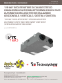 1
1
-
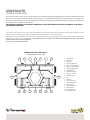 2
2
-
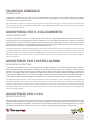 3
3
-
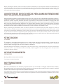 4
4
-
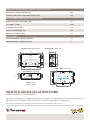 5
5
-
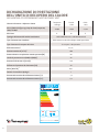 6
6
-
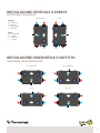 7
7
-
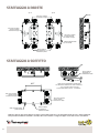 8
8
-
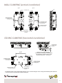 9
9
-
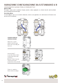 10
10
-
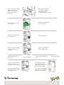 11
11
-
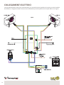 12
12
-
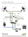 13
13
-
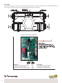 14
14
-
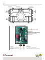 15
15
-
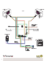 16
16
-
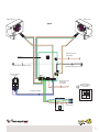 17
17
-
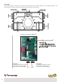 18
18
-
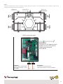 19
19
-
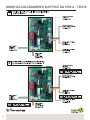 20
20
-
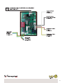 21
21
-
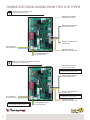 22
22
-
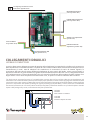 23
23
-
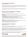 24
24
-
 25
25
-
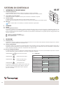 26
26
-
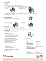 27
27
-
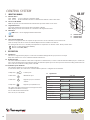 28
28
-
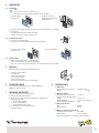 29
29
-
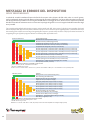 30
30
-
 31
31
-
 32
32


Tecnosystemi VR180 very high efficiency ductable static heat recovery unit Manuale del proprietario
- Tipo
- Manuale del proprietario
in altre lingue
Documenti correlati
-
Tecnosystemi VR160 high-efficiency ceiling-mounted ductable static heat recovery unit Manuale del proprietario
-
-
-
-
-
-
-
-
-