ProLights LED Fresnel Manuale utente
- Categoria
- Stroboscopi
- Tipo
- Manuale utente

EN - IT
USER MANUAL
MANUALE UTENTE
FRESNEL PROIECTOR
MINIECLFRTU-DY

All rights reserved by Music & Lights S.r.l. No part of this instruction manual may be
reproduced in any form or by any means for any commercial use.
In order to improve the quality of products, Music&Lights S.r.l. reserves the right to modify the
characteristics stated in this instruction manual at any time and without prior notice.
All revisions and updates are available in the ‘manuals’ section on site www.musiclights.it
REV.001-09/18

1
MINIECLFRTU - DY
Packing content
• MINIECLFRTU-DY
• Barn doors
• Gel frame
• User manual
TABLE OF CONTENTS
Safety
General instructions
Warnings and installation precautions
1 Introduction
1. 1 Technical specications
1. 2 Operating elements and connections
2 Installation
2. 1 Mounting
3 Functions and settings
3. 1 Operation
3. 2 Basic
3. 3 Menu structure
3. 4 DMX mode
3. 5 DMX conguration
3. 6 Screen
3. 7 Dimmer mode
3. 8 Led frequency
3. 9 Factory Reload
3. 10 Fixture Information
3. 11 Maste/Slave
3. 12 Eects
3. 13 Static
3. 14 Connection of the DMX line
3. 15 Construction of the DMX termination
3. 16 Channels DMX
4 Maintenance
4. 1 Maintenance and cleaning the unit
4. 2 Fuse replacement
4. 3 Trouble shooting
2
2
3
5
5
6
7
7
8
9
9
9
10
10
10
10
10
11
11
11
12
12
13
15
15
16

MINIECLFRTU - DY
2
SAFETY
General instruction
• The products referred to in this manual conform to the European Community Directives and are there-
fore marked with .
• The unit is supplied with hazardous network voltage (230V~). Leave servicing to skilled personnel only.
Never make any modications on the unit not described in this instruction manual, otherwise you will
risk an electric shock.
• Connection must be made to a power supply system tted with ecient earthing (Class I appliance ac-
cording to standard EN 60598-1). It is, moreover, recommended to protect the supply lines of the units
from indirect contact and/or shorting to earth by using appropriately sized residual current devices.
• The connection to the main network of electric distribution must be carried out by a qualied electrical
installer. Check that the main frequency and voltage correspond to those for which the unit is designed
as given on the electrical data label.
• This unit is not for home use, only professional applications.
• Never use the xture under the following conditions:
- in places subject to vibrations or bumps;
- in places with a temperature of over 45 °C.
• Make certain that no inammable liquids, water or metal objects enter the xture.
• Do not dismantle or modify the xture.
• All work must always be carried out by qualied technical personnel. Contact the nearest sales point for
an inspection or contact the manufacturer directly.
• If the unit is to be put out of operation denitively, take it to a local recycling
plant for a disposal which is not harmful to the environment.
Warnings and installation precautions
• If this device will be operated in any way dierent to the one described in this manual, it may suer
damage and the guarantee becomes void. Furthermore, any other operation may lead to dangers like
short circuit, burns, electric shock, etc.
• Before starting any maintenance work or cleaning the projector, cut o power from the main supply.
• Always additionally secure the projector with the safety rope. When carrying out any work, always com-
ply scrupulously with all the regulations (particularly regarding safety) currently in force in the country
in which the xture’s being used.
• Install the xture in a well ventilated place.
• Keep any inammable material at a safe distance from the xture.
• Shields, lenses or ultraviolet screens shall be changed if they have become damaged to such an extent
that their eectiveness is impaired.
• The lamp (LED) shall be changed if it has become damaged or thermally deformed.
• Never look directly at the light beam. Please note that fast changes in lighting, e. g. ashing light, may
trigger epileptic seizures in photosensitive persons or persons with epilepsy.
• Do not touch the product’s housing when operating because it may be very hot.
WARNING! Before carrying out any operations with the unit, carefully read this instruction
manual and keep it with cure for future reference. It contains important information about
the installation, usage and maintenance of the unit.

3
MINIECLFRTU - DY
- 1 - INTRODUCTION
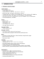
1.1 TECHNICAL SPECIFICATIONS
LIGHT SOURCE
• Source:1x38 W LEDs
• CT:(TU) 3050 K - (DY) 5000 K
• CRI:(TU) (19°) 92.2 ~ (55°) 92.1 - (DY) (19°) 82 ~ (55°) 81.9
• R9:(TU) (19°) 65.3 ~ (55°) 64.5 - (DY) (19°) 9.4 ~ (55°) 8.5
• Luminous ux:(TU) (19°) 853.77 lm (55°) 2005.9 Im - (DY) (19°) 1349.4 lm (55°) 2840.6 lm
• Lux:(TU) (19°) 744 lux - (55°) 258 lux - (DY) (19°) 978 lux - (55°) 348 lux @3m
• Lux:(TU) (19°) 267.4 lux - (55°) 92.88 lux - (DY) (19°) 352.08 lux - (55°) 125.28 lux @5m
• Source life expectancy: >50.000 h
OPTICS
• Zoom:19°~55 °
• Beam angle:19°~55 °
• Field angle:33°~78 °
• Lens diameter:3.93’’-100 mm
• Lens type: fresnel beam lens
COLOUR SYSTEM
• Colour mixing:TU or DY
DYNAMIC EFFECTS
• Static colour mode: selection of static dimmer
• Auto mode: built-in programs with execution speed adjustment
BODY
• Hardware on-board: lter frame, 4 doors barndoor, omega bracket spigot
• Body: aluminium die-casting
• Body colour: black
CONTROL
• Protocols: DMX512, RDM
• DMX channels:1 ch - 2 ch 1 - 2 ch 2 - 3 ch - 5 channel
• RDM: RDM ready for xture remote monitor and settings
• Display: black OLED high resolution display
• Firmware upgrade: yes, via USB-DMX interface (UPBOX1) not included
• Master/Slave: for synchronized operation of more units linked in a chain
ELECTRONICS
• Dimmer: linear 0~100%, manual knob dimmer
• Dimmer curves:4 dierent dimming curves available
• Strobe / shutter:28 Hz, electronic
• Operating temperature: -10° ~ +45°
• Flicker: icker free frequency with adjustable PWM
• Selectable PWM: 600~25K Hz

MINIECLFRTU - DY
4
ELECTRICAL
• Power consumption:48
• Power supply: 100-240V – 50/60Hz
• Power consumption (at 230V):33.2 W
• Power consumption (at 120V):31.8 W
PHYSICAL
• Cooling: natural cooling of the peculiar chassis and to absence of fans
• Signal connection: DMX 5p IN/OUT
• Power connection:Power cable
• IP rating:20
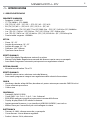
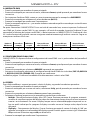
• Dimensions (WxHxD):203x191x279 mm
• Weight:2.38 kg
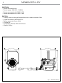
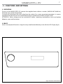
Fig.1 - Technical drawing
191 [7.51 in]
279 [10.98 in]
203 [7.99 in]

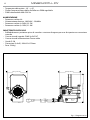
Fig.2
1
6
7
9
8
5
2
3
4
4
5
8
9
5
MINIECLFRTU - DY
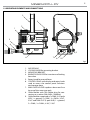
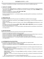
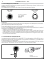
1.2 OPERATING ELEMENTS AND CONNECTIONS
1. AIR OPENING
2. LOCKING KNOB for mounting bracket
3. MOUNTING BRACKET
4. BARNDOOR HOLDER for insertion and locking
barn door
5. Rotary knob for manual focus
6. CONTROL PANEL with display and rotary knob
used to access the control panel functions
and manage them
7. MAIN FUSE HOLDER: replace a burnt-out fuse
by one of the same type only
8. Cable exible with 16A Shuko plug for con-
nection to a socket (100-240V~/50-60Hz)
9. Cable exible composed of a DMX IN (5-pole
XLR): 1 = ground, 2 = DMX-, 3 = DMX+, 4 N/C,
5 N/C and DMX OUT (5-pole XLR): 1 = ground,
2 = DMX-, 3 = DMX+, 4 N/C, 5 N/C

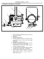
Fig.3
MINIECLFRTU - DY
6
- 2 - INSTALLATION
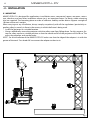
2.1 MOUNTING
MINIECLFRTU-DY is designed for applications in exhibition areas, commercial spaces, museums, restau-
rant, churches, and any other installation where size is an important factor. For xing, stable mounting
clips are required. The mounting place must be of sucient stability and be able to support a weight of
10 times of the unit’s weight.
When carrying out any installation, always comply scrupulously with all the regulations (particularly re-
garding safety) currently in force in the country in which the xture’s being used.
• Install the projector at a suitable location.
• Always additionally secure the projector with the safety rope from falling down. For this purpose, fas-
ten the safety rope at a suitable position so that the maximum fall of the projector will be 20 cm. The
adjust the projector and use the knobs.
NOTE - For the installation of the MINIECLFRTU-DY make sure that the ridge of the adaptor is in with the
groove of the track. Turn knobs 90° to connect the adaptor to the circuit.

7
MINIECLFRTU - DY
- 3 - FUNCTIONS AND SETTINGS
3.1 OPERATION
To turn on the MINIECLFRTU-DY connect the supplied main cable to a socket (100-240 VAC-50/60 Hz).
Then the unit is ready for operation.
To switch o, disconnect the mains plug from the socket. For a more convenient operation it is recom-
mended to connect the unit to a socket which can be switched on and o via a light switch.
ATTENTION - Mains voltage must be switched o before mounting; maintenance; insert and replace
Adaptors; spots and luminaires.
3.2 BASIC
Access control panel functions using the rotary knob located directly on the left the LED Display (g.5).
Fig.4- Functions of the buttons

MENU
1 CONNECT
ð
DMX Address
ð
(001-512)
DMX Mode
ð
EASY-1Ch
BASIC-2Ch 1
BASIC-2Ch 2
BASIC-3Ch
STANDARD–5CH
2 SETUP
ð
Screen
ð
Back Light
ð
On
10S
20S
30S
ð
Flip Display
ð
NO-Yes
3 ADVANCED
ð
Dimmer Mode
ð
O
Dimmer 1
Dimmer 2
Dimmer 3
Led Frequency
ð
600Hz
1200 Hz
2000 Hz
4000 Hz
6000Hz
25kHZ
Factory Reload
ð
NO-Yes
4 INFORMATION
ð
Fixture Hours
ð
0-9999
Version
ð
V1.0
Temperature
ð
°C
UID
ð
15D00223****
5 STAND ALONE
ð
Master/Slave
ð
Master
Slave
Eect
ð
Eect 1
Eect 2
Eect 3
Eect 4
Static
ð
Dimmer
Strobe
MINIECLFRTU - DY
8
3.3 MENU STRUCTURE

9
MINIECLFRTU - DY
3.4 DMX MODE
• Press rotary knob to access the main menu.
• Rotate knob to scroll the menu, select Connect, then press the rotary knob to enter the next menu.
• Press on UP / DOWN to select DMX ADDRESS, and press the rotary knob to conrm.
• Rotate knob and press on UP/DOWN to select the desired value (001-512).
• Press rotary knob to store.
• Rotate knob and press on ← to go back or to meet the waiting time to exit the setup menu.
To able to operate the MINIECLFRTU-DY with a light controller, adjust the DMX start address for the rst a
DMX channel. If e. g. address 33 on the controller is provided for controlling the function of the rst DMX
channel, adjust the start address 33 on the MINIECLFRTU-DY. The other functions of the light eect panel
are then automatically assigned to the following addresses.
An example with the start address 33 is shown below:
3.5 DMX CONFIGURATION
MINIECLFRTU-DY is equipped with dierent DMX conguration.
• Press rotary knob to access the main menu.
• Rotate knob to scroll the menu, select Connect, then press the rotary knob to enter the next menu.
• Rotate knob to select DMX MODE, and press the rotary knob to conrm.
• Select the desired DMX conguration (EASY-1Ch, BASIC-2Ch 1, BASIC-2Ch 2, BASIC-3Ch, STANDARD–5CH) through
the rotary knob.
The tables on page 13 indicate the operating mode and DMX value.
3.6 SCREEN
You can change the following parameters related to the display, following the same procedure:
• Press rotary knob to access the main menu.
• Rotate knob to scroll the menu, select Set Up, then press the rotary knob to enter the next menu.
• Rotate knob to scroll through the menu, then select Screen, and press the rotary knob to enter the next
menu.
• Rotate knob to scroll through the menu, and then select one of the following settings for the display
and press the rotary knob to display it.
- Back Light - Backlight display Auto O. This feature allows you to automatically turn o the backlight
after a specied time that you can set using the arrow buttons. To have the display always on select
On or choose another value to turn o the display after the amount of time you choose.
- Flip Display - Orientation of the display. This function allows you to rotate the display 180° to get a
better view of the display when the unit is hanging upside down. Select YES to activate or NO to dis-
able this function.
• Press the rotary knob to conrm your choice.
• Rotate knob and press on ← to go back or to meet the waiting time to exit the setup menu.
Numero
canali DMX
Indirizzo di
start (esempio)
Indirizzo DMX
occupati
Prossimo indirizzo di start
possibile per unità n°1
Prossimo indirizzo di start
possibile per unità n°2
Prossimo indirizzo di start
possibile per unità n°3
5 33 33 - 37 38 43 48

MINIECLFRTU - DY
10
3.7 DIMMER MODE
Enter in Dimmer mode to select specic dimming curve, press the rotary knob to access the main menu.
• Rotate knob to scroll the menu, select Advanced, then press the rotary knob to enter the next menu.
• Rotate knob to scroll through the menu, then select Dimmer mode, and press the rotary knob to conrm.
• Rotate knob to select O - Dimmer1 - Dimmer2 - Dimmer3.
• Press the rotary knob to conrm your choice.
• Rotate knob and press on ← to go back or to meet the waiting time to exit the setup menu.
3.8 LED FREQUENCY
To adjust the frequency of the LEDs, press the rotary knob to access the main menu.
• Rotate knob to scroll the menu, select Advanced, then press the ENTER button to enter the next menu.
• Rotate knob to scroll through the menu, then select LED Frequency, and press the button ENTER to con-
rm.
• Select the frequency (600Hz - 1200Hz - 2000Hz - 4000Hz - 6000Hz - 25kHz) using the rotary knob buttons.
• To conrm, press the rotary knob.
• Rotate knob and press on ← to go back or to meet the waiting time to exit the setup menu.
3.9 FACTORY RELOAD
Select this function to reset the unit to the factory settings:
• To activate Reset Factory display press the rotary knob to access the main menu.
• Rotate knob to scroll the menu, select Advanced, then press the rotary knob to enter the next menu.
• Rotate knob to scroll through the menu, then select Factory Reload, and press the rotary knob to conrm.
• Rotate knob and press on ← to go back or to meet the waiting time to exit the setup menu.
3.10 FIXTURE INFORMATION
To view all the information on the device, proceed as follows:
• Press the rotary knob to access the main menu.
• Rotate knob button to scroll the menu, select Information, then press the rotary knob to enter the next
menu.
• Rotate knob button to scroll through the menu, then select one of the following information and press
the rotary knob to display it.
- Fixture Time - Through the Fixture Time function you can display the operating time of the projector.
- Software Version - Through Temperature function you can display the temperature of the device.
- Temperature - Through Temperature function you can display the temperature of the device.
- UID - This option shows the RDM identication number.
• Rotate knob and press on ← to go back or to meet the waiting time to exit the setup menu.
3.11 MASTER SLAVE
Press the rotary knob button to access the main menu.
• Rotate knob button to scroll the menu, select Stand Alone, then press the rotary knob to enter the next
menu.
• Rotate knob button to scroll through the menu, select Master/Slave and press the rotary knob to conrm
your choice.
• Rotate knob button to select the mode of operation:
- Master, if the unit is connected in series with other units and it acts as the Master;
- Slave, if the unit is not connected to other units.

11
MINIECLFRTU - DY
• Press the rotary knob to conrm your choice.
• Rotate knob and press on ← to go back or to meet the waiting time to exit the setup menu.
3.12 EFFECTS
The unit has pre-programmed eects that can be set through the following procedure:
• Press the rotary knob to access the main menu.
• Rotate knob button to scroll the menu, select Eects, then press the rotary knob to enter the next menu.
• Rotate knob button to select the mode of operation: Eects 1, Eects 2, Eects 3, Eects 4.
• Press the rotary knob to conrm your choice.
• Rotate knob and press on ← to go back or to meet the waiting time to exit the setup menu.
3.13 STATIC
The unit allows you to create congurations that can be set through the following procedure:
• To enter to static static mode, press the rotary knob to access the main menu.
• Rotate knob button to scroll the menu, select Stand Alone, then press the rotary knob to enter the next
menu.
• Rotate knob button to scroll through the menu, select Static and press rotary knob to conrm your
choice.
• Throught the rotary knob select Dimmer o Strobe and press the rotary knob to conrm the desired func-
tion.
• Set the value (000 - 255), Throught the rotary knob, then press it to conrm
• Rotate knob and press on ← to go back or to meet the waiting time to exit the setup menu.
NOTE: once the plug of the power cord has been connected to a power outlet, to access the Dimmer mode
directly, simply press the knob twice consecutively. After that, choiche the desired value.
NOTE: once the projector is connected to a power outlet, to directly access the Dimmer mode, simply dou-
ble click on the knob, rotating it. After that, choiche the desired value.

MINIECLFRTU - DY
12
Fig.5
Fig.6
3.14 CONNECTION OF THE DMX LINE
DMX connection employs standard XLR connectors. Use shielded pair-twisted cables with 120Ω imped-
ance and low capacity.
The following diagram shows the connection mode:
ATTENTION
The screened parts of the cable (sleeve) must never be connected to the system’s earth, as this would
cause faulty xture and controller operation.
Over long runs can be necessary to insert a DMX level matching amplier.
For those connections the use of balanced microphone cable is not recommended because it cannot
transmit control DMX data reliably.
• Connect the controller DMX input to the DMX output of the rst unit.
• Connect the DMX output to the DMX input of the following unit. Connect again the output to the input
of the following unit until all the units are connected in chain.
• When the signal cable has to run longer distance is recommended to insert a DMX termination on the
last unit.
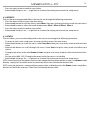
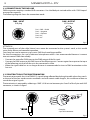
3.15 CONSTRUCTION OF THE DMX TERMINATION
The termination avoids the risk of DMX 512 signals being reected back along the cable when they reach-
es the end of the line: under certain conditions and with certain cable lengths, this could cause them to
cancel the original signals.
The termination is prepared by soldering a 120Ω 1/4 W resistor between pins 2 and 3 of the 5-pin male XLR
connector, as shown in gure.
DMX - OUTPUT
XLR socket
DMX - INPUT
XLR plug
Pin1 : GND - Shield
Pin2 : - Negative
Pin3 : + Positive
Pin4 : N/C
Pin5 : N/C
Example:
5 pin XLR connector

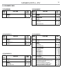
1 CHANNEL
MODE
FUNCTION DMX
Value
1 Ch
1
DIMMER
0~100% 000 - 255
5 CHANNELS
MODE
FUNCTION DMX
Value
5 Ch
1
DIMMER
0~100% 000 - 255
2
STROBE
No Function
Strobe slow to fast
000 - 010
011 - 255
3
AUTO PROGRAMS
No Function
Auto Program 1
Auto Program 2
Auto Program 3
Auto Program 4
000 - 010
011 - 070
071 - 130
131 - 190
191 - 255
4
AUTO SPEED
Speed slow to fast 000 - 255
5
DIMMER SPEED MODE
Preset dimmer speed from display menu
Dimmer speed mode o
Dimmer speed mode1 (fast speed)
Dimmer speed mode2 (middle speed)
Dimmer speed mode3 (slow speed)
000 - 051
052 - 101
102 - 152
153 - 203
204 - 255
3 CHANNELS
MODE
FUNCTION DMX
Value
3 Ch
1
DIMMER
0~100% 000 - 255
2
DIMMER FINE
0~100% 000 - 255
3
STROBE
No Function
Strobe slow to fast
000 - 010
011 - 255
2 CHANNELS 1
MODE
FUNCTION DMX
Value
2 Ch1
1
DIMMER
0~100% 000 - 255
2
DIMMER FINE
0~100% 000 - 255
2 CHANNELS 2
MODE
FUNCTION DMX
Value
2 Ch2
1
DIMMER
0~100% 000 - 255
2
STROBE
No Function
Strobe Slow to Fast
000 - 010
011 - 255
13
MINIECLFRTU - DY
3.16 CHANNELS DMX

MINIECLFRTU - DY
14
- 4 - MAINTENANCE
4.1 MAINTENANCE AND CLEANING THE UNIT
• Make sure the area below the installation place is free from unwanted persons during setup.
• Switch o the unit, unplug the main cable and wait until the unit has cooled down.
• All screws used for installing the device and any of its parts should be tightly fastened and should not
be corroded.
• Housings, xations and installation spots (ceiling, trusses, suspensions) should be totally free from any
deformation.
• The main cables must be in impeccable condition and should be replaced immediately even when a
small problem is detected.
• It is recommended to clean the front at regular intervals, from impurities caused by dust, smoke, or
other particles to ensure that the light is radiated at maximum brightness. For cleaning, disconnect the
main plug from the socket. Use a soft, clean cloth moistened with a mild detergent. Then carefully wipe
the part dry. For cleaning other housing parts use only a soft, clean cloth. Never use a liquid, it might
penetrate the unit and cause damage to it.
•
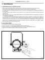
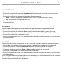
4.2 FUSE REPLACEMENT
1. Disconnect this product from the power outlet.
2. Using a screwdriver, unscrew the fuse holder cap from the housing.
3. Remove the blown fuse and replace with a good fuse of the same type and rating.
4. Screw the fuse holder cap back in place and reconnect power
Fig.7

15
MINIECLFRTU - DY
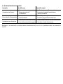
Problems Possible causes Checks and remedies
Fixture does not light up
• No mains supply
• Dimmer fader set to 0
• Faulty LED
• Check the power supply voltage
• Increase the value of the dimmer channels
• Replace the LED board
General low light intensity
• Dirty lens assembly
• Misaligned lens assembly
• Clean the xture regularly
• Install lens assembly properly
Fixture does not power up
• No power
• Loose or damaged power cord
• Check for power on power outlet
• Check power cord
Contact an authorized service center in case of technical problems or not reported in the table can not be
resolved by the procedure given in the table.
4.3 TROUBLESHOOTING

REV.001-09/18
Music & Lights S.r.l. si riserva ogni diritto di elaborazione in qualsiasi forma delle presenti istruzioni per l’uso.
La riproduzione - anche parziale - per propri scopi commerciali è vietata.
Al ne di migliorare la qualità dei prodotti, la Music&Lights S.r.l. si riserva la facoltà di modicare, in
qualunque momento e senza preavviso, le speciche menzionate nel presente manuale di istruzioni.
Tutte le revisioni e gli aggiornamenti sono disponibili nella sezione 'Manuali' sul sito www.musiclights.it

3
MINIECLFRTU - DY
• MINIECLFRTU-DY
• Barb doors
• Gel frame
• Manuale utente
Contenuto dell'imballo:
INDICE
Sicurezza
Avvertenze generali
Attenzioni e precauzioni per l’installazione
1 Introduzione
1. 1 Speciche tecniche
1. 2 Elementi di comando e di collegamento
2 Installazione
2. 1 Montaggio
3 Funzioni e impostazioni
3. 1 Funzionamento
3. 2 Impostazione base
3. 3 Struttura menù
3. 4 Modalità DMX
3. 5 Congurazione canali
3. 6 Screen
3. 7 Dimmer mode
3. 8 Frequenza led
3. 9 Factory Reload
3. 10 Informazioni sul dispositivo
3. 11 Master/Slave
3. 12 Eects
3. 13 Static
3. 14 Collegamenti della linea DMX
3. 15 Costruzione del terminatore DMX
3. 16 Canali DMX
4 Manutenzione
4. 1 Manutenzione e pulizia del sistema ottico
4. 2 Sostituzione fusibile
4. 3 Risoluzione dei problemi
4
4
5
7
7
8
9
9
10
11
11
11
12
12
12
12
12
13
13
13
14
14
15
16
16
17

MINIECLFRTU - DY
4
ATTENZIONE! Prima di effettuare qualsiasi operazione con l’unità, leggere con attenzione
questo manuale e conservarlo accuratamente per riferimenti futuri. Contiene informazioni
importanti riguardo l’installazione, l’uso e la manutenzione dell’unità.
SICUREZZA
Avvertenze generali
• I prodotti a cui questo manuale si riferisce sono conformi alle Direttive della Comunità Europea e per-
tanto recano la sigla .
• Il dispositivo funziona con pericolosa tensione di rete 230V~. Non intervenire mai al suo interno al di
fuori delle operazioni descritte nel presente manuale; esiste il pericolo di una scarica elettrica.
• È obbligatorio eettuare il collegamento ad un impianto di alimentazione dotato di un’eciente messa
a terra (apparecchio di Classe I secondo norma EN 60598-1). Si raccomanda, inoltre, di proteggere le
linee di alimentazione delle unità dai contatti indiretti e/o cortocircuiti verso massa tramite l’uso di
interruttori dierenziali opportunamente dimensionati.
• Le operazioni di collegamento alla rete di distribuzione dell’energia elettrica devono essere eettuate
da un installatore elettrico qualicato. Vericare che frequenza e tensione della rete corrispondono alla
frequenza ed alla tensione per cui l’unità è predisposta, indicate sulla targhetta dei dati elettrici.
• L’unità non per uso domestico, solo per uso professionale.
• Evitare di utilizzare l’unità:
- in luoghi soggetti a vibrazioni, o a possibili urti;
- in luoghi a temperatura superiore ai 45°C.
• Evitare che nell’unità penetrino liquidi inammabili, acqua o oggetti metallici.
• Non smontare e non apportare modiche all’unità.
• Tutti gli interventi devono essere sempre e solo eettuati da personale tecnico qualicato. Rivolgersi al
più vicino centro di assistenza tecnica autorizzato.
• Se si desidera eliminare il dispositivo denitivamente, consegnarlo
per lo smaltimento ad un’istituzione locale per il riciclaggio.
Attenzioni e precauzioni per l’installazione
• Se il dispositivo dovesse trovarsi ad operare in condizioni dierenti da quelle descritte nel presente
manuale, potrebbero vericarsi dei danni; in tal caso la garanzia verrebbe a decadere. Inoltre, ogni altra
operazione potrebbe provocare cortocircuiti, incendi, scosse elettriche, rotture etc.
• Prima di iniziare qualsiasi operazione di manutenzione o pulizia sull’unità togliere la tensione dalla rete
di alimentazione.
• È assolutamente necessario proteggere l’unità per mezzo di una fune di sicurezza. Nell’eseguire qualsi-
asi intervento attenersi scrupolosamente a tutte le normative (in materia di sicurezza) vigenti nel paese
di utilizzo.
• Installare l’unità in un luogo ben ventilato.
• Mantenere i materiali inammabili ad una distanza di sicurezza dall’unità.
• I ltri, le lenti o gli schermi ultravioletti se danneggiati possono limitare la loro ecienza.
• I LED devono essere sostituiti se danneggiati o termicamente deformati.
• Non guardare direttamente il fascio luminoso. Tenete presente che i veloci cambi di luce possono pro-
vocare attacchi d’epilessia presso persone fotosensibili o epilettiche.
• Non toccare l’alloggiamento del prodotto quando è in funzione perché potrebbe essere molto caldo.
La pagina si sta caricando...
La pagina si sta caricando...
La pagina si sta caricando...
La pagina si sta caricando...
La pagina si sta caricando...
La pagina si sta caricando...
La pagina si sta caricando...
La pagina si sta caricando...
La pagina si sta caricando...
La pagina si sta caricando...
La pagina si sta caricando...
La pagina si sta caricando...
La pagina si sta caricando...
La pagina si sta caricando...
La pagina si sta caricando...
La pagina si sta caricando...
-
 1
1
-
 2
2
-
 3
3
-
 4
4
-
 5
5
-
 6
6
-
 7
7
-
 8
8
-
 9
9
-
 10
10
-
 11
11
-
 12
12
-
 13
13
-
 14
14
-
 15
15
-
 16
16
-
 17
17
-
 18
18
-
 19
19
-
 20
20
-
 21
21
-
 22
22
-
 23
23
-
 24
24
-
 25
25
-
 26
26
-
 27
27
-
 28
28
-
 29
29
-
 30
30
-
 31
31
-
 32
32
-
 33
33
-
 34
34
-
 35
35
-
 36
36


ProLights LED Fresnel Manuale utente
- Categoria
- Stroboscopi
- Tipo
- Manuale utente
in altre lingue
- English: ProLights LED Fresnel User manual
Documenti correlati
-
ProLights LED Fresnel Manuale utente
-
-
ProLights Single source multipurpose LED PAR available in TU, DY and UV version Manuale utente
-
-
-
-
-
-
-