Tecnosystemi SMART SIRIO programmable thermostat Manuale del proprietario
- Tipo
- Manuale del proprietario

1
MANUALE D’USO
Tecnosystemi S.p.A. - Società Benefit
www.tecnosystemi.com
via dell’Industria, 2/4 - Z.I. San Giacomo di Veglia
31029 Vittorio Veneto (Treviso) - Italy
Phone +39 0438.500044 Fax +39 0438.501516
Numero Verde 800 904474 (only for Italy)
email: [email protected]
C.F. - P. IVA - R.I.TV IT02535780247 | Cap. Soc. € 5.000.000,00 i.v.
REV. 03 / 25-09-2023
COD. CLI00074
“SMART SIRIO”
CRONOTERMOSTATO AMBIENTE CON
COMMUTAZIONE ESTATE/INVERNO
• cod. SGC200001

2
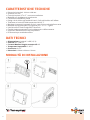
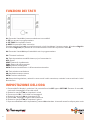
CARATTERISTICHE TECNICHE
DATI TECNICI
• Dimensioni standard: 140 mm x 90 mm
• Spessore: 32 mm
• Controllo impianti 2T e 4T + consenso ventilatore
• Modalità per riscaldamento a pavimento
• Facilmente installabile a parete
• Design che si abbina agli ambienti interni, facile ed intuitivo nell’utilizzo
• Tolleranza sul controllo della temperatura di 0.5° C
• Mantiene i parametri impostati anche in caso di interruzione della corrente
• Modalità di programmazione: programmi per 7 /5 + 1 + 1 giorni
• Unità di misura: Gradi Centigradi e Fahrenheit
• Cambio stagione automatico tra riscaldamento e raffrescamento
• Supporta il ritardo di blocco del compressore
• Promemoria per sostituzione filtro
• Alimentazione: a batteria 2 x AA (1,5 V)
• Sensore: NTC (10K) 1%
• Corrente Massima singolo contatto relè: 2A
• Temperature impostabili: 5~35°C
• Precisione: ±0,5°C
• Dimensioni: 140mm x 90mm x 32mm
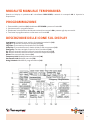
MODALITÀ DI INSTALLAZIONE
1H/1C system((1 transformer))1H/1C system((2 transformer))
Rc power 【1】Rc power (cooling transformer)【1,2】
Rh RH+RC joined by jumper Rh power (heating transformer)【1,2】
W heat relay W heat relay
Y compressor contactor Y compressor contactor
G fan relay G fan relay
C/S1 24V common/remote sensor【3】C/S1 24V common /remote sensor【3】
S2 remote sensor S2 remote sensor
2H/2C System((1transformer))2H/2C system((2transformer))
Rc power 【1】Rc power【1,2】
Rh RH+RC joined by jumper Rh RH+RC joined by jumper【1,2】
W heat relay 1W heat relay1
Y Compressor contactor 1 Y compressor contactor 1
W heat relay 2W2 heat relay 2
Y compressor contactor 2Y2 compressor contactor 2
G fan relay G fan relay
C/S1 24V common/remote sensor【3】C/S1 24V common/remote sensor【3,4】
S2 remote sensor S2 remote sensor
1H/1C heat pump((no auxiliary heat))2H/2C heat pump (no auxiliary heat)
Rc Power 【1】Rc Power (cooling transformer) 【1,2】
Rh RH+RC joined by jumper Rh power(heating transformer) 【1,2】
Y compressor relay W heat relay 1
O changeover valve energized in cooling Y cool relay 1
B changeover valve energized in heating W2 heat relay 2
G fan relay Y2 cool relay 2
C/S1 24V common/remote sensor【3】G fan relay
S2 remote sensor C/S1 24Vcommon/remote sensor【3,4】
S2 remote sensor
2H/1C heat pump((with auxiliary heat))3H/2Cheat pump((with auxiliary heat))
Lequipment monitor【5】Lequipment monitor【5】
Rc power 【1】Rc power【1】
Rh RH+RC joined by jumper Rh RH+RC joined by jumper
Y compressor relay Y1 compressor relay1
E emergency heat relay【6】E emergency heat relay【6】
Aux auxiliary heat relay (heat 2) 【6】Aux auxiliary heat relay(heat 2) 【6】
O changeover valve energized in cooling O changeover valve energized in cooling
B changeover valve energized in heating B changeover valve energized in heating
G fan relay Y2 compressor relay 2
C/S1 24V common/remote sensor【3】G fan relay 2
S2 remote sensor C/S1 24Vcommon /remote sensor【3】
S2 remote sensor
How to install

3
CONTATTO RELÈ CIRCUITO CALDO: terminali 10 e 5
CONTATTO RELÈ CIRCUITO FREDDO: terminali 3 e 9
CONTATTO CONSENSO VENTILAZIONE: terminali 3 e 4
ATTENZIONE
LAVORARE CON I COMPONENTI ELETTRICI ALIMENTATI PUÒ CAUSARE CORTO CIRCUITI O DANNEGGIARE
IL DISPOSITIVO. SCOLLEGARE L’ALIMENTAZIONE PRIMA DELL’INSTALLAZIONE!
CONNESSIONI ELETTRICHE
39
10
5
4
comune
comune
fan
contatto freddo
contatto caldo

4
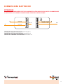
SCHEMA COLLEGAMENTO ELETTROVALVOLE IMPIANTO 2T E 4T
MORSETTIERA DEL CRONOTERMOSTATO SMART SIRIO.
RELE’ DEL FREDDO
RELE’ DEL CALDO
CON CRONOTERMOSTATO SMART SIRIO IN MODO «CALDO+ FREDDO» 4T
L
ev
N
ev
N
3
5
9
10
MORSETTIERA DEL CRONOTERMOSTATO SMART SIRIO.
RELE’ DEL FREDDO
RELE’ DEL CALDO
CON CRONOTERMOSTATO SMART SIRIO IN MODO «CALDO+ FREDDO» 2T
ev
NL
3
5
9
10
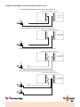
MORSETTIERA DEL CRONOTERMOSTATO SMART SIRIO.
RELE’ DEL FREDDO
RELE’ DEL CALDO
CON CRONOTERMOSTATO SMART SIRIO IN MODO «SOLO CALDO» 2T
ev
NL
3
5
9
10
MORSETTIERA DEL CRONOTERMOSTATO SMART SIRIO.
RELE’ DEL FREDDO
RELE’ DEL CALDO
CON CRONOTERMOSTATO SMART SIRIO IN MODO «SOLO FREDDO» 2T
ev
N L
3
5
9
10

5
SCHEMA ELETTRICO
Tel. +39 0438-500044 - Fax -39 0438-501516
[email protected] www.tecnosystemi.com
Via Mattei, 2/4 - Z.I. S. Giacomo di Veglia
31029 Vittorio Veneto (TV) Italia
schema serrande Sirio 2.0 con smart sirio
CLI00074
REV. 01 / 17-06-2021
RIF. PAG. 5
IN OUT OUT
ALIMENTAZIONE
230Vac.
CONTATTO CHIUSO, APRE LA SERRANDA.
CONTATTO APERTO, CHIUDE LA SERRANDA.
IN
SIRIO 2.0
POINT MASTER
IG
CHIUDE ALL’APERTURA DELLA SERRANDA.
APRE ALLA CHIUSURA DELLA SERRANDA.
CONTATTO
3
5
9
10
MORSETTIERA DEL CRONOTERMOSTATO SMART SIRIO.
RELE’ DEL FREDDO
RELE’ DEL CALDO
COLLEGAMENTO DEL CONTATTO ON-OFF DELLA SERRANDA SIRIO 2.0,
CON CRONOTERMOSTATO SMART SIRIO IN MODO «SOLO FREDDO»
IN OUT OUT
ALIMENTAZIONE
230Vac.
CONTATTO CHIUSO, APRE LA SERRANDA.
CONTATTO APERTO, CHIUDE LA SERRANDA.
IN
SIRIO 2.0
POINT MASTER
IG
CHIUDE ALL’APERTURA DELLA SERRANDA.
APRE ALLA CHIUSURA DELLA SERRANDA.
CONTATTO
3
5
9
10
MORSETTIERA DEL CRONOTERMOSTATO SMART SIRIO.
RELE’ DEL FREDDO
RELE’ DEL CALDO
COLLEGAMENTO DEL CONTATTO ON-OFF DELLA SERRANDA SIRIO 2.0,
CON CRONOTERMOSTATO SMART SIRIO IN MODO «SOLO CALDO»
COLLEGAMENTO DEL CONTATTO ON-OFF DELLA SERRANDA SIRIO 2.0,
CON CRONOTERMOSTATO SMART SIRIO IN MODO «FREDDO + CALDO»
Per il funzionamento con la serranda Sirio 2.0 Point collegare il connettore della serranda master denominato
“IN” ai seguenti morsetti a seconda che si scelga di utilizzare l’impianto canalizzato in modalità caldo o freddo.
Vedi schemi di collegamento successivi:

6
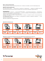
FUNZIONI DEI TASTI
IMPOSTAZIONE DELL’ORA
K1: Premendo il tasto K1 si possono selezionare tre modalità:
1. SET: per entrare in programmazione
2. SET TIME: Per impostare l’orario
3. NEXT: Per passare al dato successivo
Tenendo premuto il tasto K1 per qualche secondo, si può visualizzare il sensore remoto, la funzione Chg UV e
la funzione Chg Filter per passare da una funzione all’altra continuare a premere il tasto K1
K2: Premendo il tasto K2 dopo il tasto K1 si entra in programmazione
K3: È il tasto di conferma
K4: Tasto impostazione modalità sistema, si può commutare in:
OFF: Spento
HEAT: Sistema di riscaldamento
COOL: Sistema di raffrescamento
EMER: Sistema di emergenza
AUTO: Sistema riscaldamento / raffrescamento automatico
K5: Tasto selezione ventilazione.
ON: Ventilazione sempre accesa
AUTO: Funzione automatica
K6: Manopola di regolazione, ruotando in senso orario i valori aumentano, ruotando in senso antiorario i valori
diminuiscono.
1. Premere K1. Sul display in posizione 7 al posto della scritta SET appare SET TIME. Premere di nuovo K1,
comincerà a lampeggiare l’icona dei minuti
2. Ruotare la manopola K6 per impostare i minuti
3. Premere quindi K1, l’icona delle ore lampeggerà
4. Ruotare la manopola K6 per impostare le ore
5. Premere K1, lampeggerà il giorno della settimana
6. Ruotare la manopola K6 per impostare il giorno
7. Dopo aver effettuato tutte le impostazioni, premere K3 o attendere 10 secondi senza far nulla per poter uscire
HY818 thermostat manual
HY818 series thermostat can be used to control temperature for 3heat/2 cool system ,,heat
pump system etc 。。
Feature
Standard size is 140*90mm
Thickness is 32mm
Surface mounted type,easy to install。
Indoor/remote sensor selection design,safer and more comfortable to use
0.5℃accuracy ,precise control temperature
Power-down memory function, easy to use
Program mode :7 /5+1+1 day program
Support Centigrade and Fahrenheit
Auto changeover heat/cool
Support compressor lockout delay
Reminder of replacement filter
Reminder of replacement UV lamp
Technical data
Battery supply or AC20-28V
Sensor::NTC(10K)1%
load Current :2A(30VDC)
Default of setting point:5~35℃
accuracy:±0.5℃
Remote sensor:option (NTC)
Size:140*90*32mm
Display description of icons
Low Battery:should replace battery
Chg UV:should replace UV lamp
Chg Filter:should replace /clean filter
Comp Dly:during compressor lockout delay
Emergency:emergency heat
E1:Temperature controller indoor sensor failure alarm
E2:Temperature controller remote sensor failure alarm
Alarm:Other system failures
Temporary Hold:temporary Manual mode
Permanent Hold:manual mode
Using Schedule:program mode
Button feature
K1:Select key.After short pressing K1 key, (7) will display three following selection:
SET:This option is to set SYSTEM (16), FAN(13), program (8) parameters
SET TIME:Set the system clock
NEXT:next item
Long press K1---
(7)
display next ---(21)query remote sensor temperature/UV lamp replacement run
time /filter replacement run time

7
MODALITÀ MANUALE TEMPORANEA
Quando sul display in posizione 8 è visualizzato RUN SCHED, ruotando la manopola K6 si imposta la
temperatura.
PROGRAMMAZIONE
1. Premere K1 in posizione (13) visualizzare SET SCHED e premere il tasto K5.
2. Il sistema entra in programmazione.
3. Selezionare le temperature desiderate ruotando la manopola K6 e passare agli step successivi.
4. Terminata la programmazione confermare con il tasto K3
DESCRIZIONE DELLE ICONE SUL DISPLAY
Low battery: Le batterie sono scariche è necessario sostituirle. (23)
Chg UV: È necessario sostituire la lampada UV (12)
Chg Filter: È necessario pulire/sostituire il filtro (12)
Comp Dly.: Si accende durante il ritardo del blocco del compressore (12)
Emergency: Funzione antigelo fa partire l’unità riscaldante (19)
E1: Allarme anomalia sensore interno di controllo temperatura (17)
E2: Allarme anomalia sensore remoto di controllo temperatura (17)
Alarm: Altre anomalie del sistema (10)
Temporary Hold: Modalità attesa temporanea (18)
Permanent Hold: Modalità manuale (18)
Using Schedule: Modalità di programmazione (19)
HY818 thermostat manual
HY818 series thermostat can be used to control temperature for 3heat/2 cool system ,,heat
pump system etc 。。
Feature
Standard size is 140*90mm
Thickness is 32mm
Surface mounted type,easy to install。
Indoor/remote sensor selection design,safer and more comfortable to use
0.5℃accuracy ,precise control temperature
Power-down memory function, easy to use
Program mode :7 /5+1+1 day program
Support Centigrade and Fahrenheit
Auto changeover heat/cool
Support compressor lockout delay
Reminder of replacement filter
Reminder of replacement UV lamp
Technical data
Battery supply or AC20-28V
Sensor::NTC(10K)1%
load Current :2A(30VDC)
Default of setting point:5~35℃
accuracy:±0.5℃
Remote sensor:option (NTC)
Size:140*90*32mm
Display description of icons
Low Battery:should replace battery
Chg UV:should replace UV lamp
Chg Filter:should replace /clean filter
Comp Dly:during compressor lockout delay
Emergency:emergency heat
E1:Temperature controller indoor sensor failure alarm
E2:Temperature controller remote sensor failure alarm
Alarm:Other system failures
Temporary Hold:temporary Manual mode
Permanent Hold:manual mode
Using Schedule:program mode
Button feature
K1:Select key.After short pressing K1 key, (7) will display three following selection:
SET:This option is to set SYSTEM (16), FAN(13), program (8) parameters
SET TIME:Set the system clock
NEXT:next item
Long press K1---
(7)
display next ---(21)query remote sensor temperature/UV lamp replacement run
time /filter replacement run time

8
Modalità di raffrescamento
Modalità di riscaldamento/Modalità automatica/Modalità riscaldamento d’emergenza
Sveglia Uscita Rientro Sonno
06:00 24°C 08:00 29°C 17:00 24°C 22:00 26°C
Sveglia Uscita Rientro Sonno
06:00 21°C 08:00 17°C 17:00 21°C 22:00 17°C
Blocco / Sblocco della tastiera
Tieni premuto K4 e K5 per 5 secondi per bloccare e / o sbloccare la tastiera, icona lucchetto display (24).
Modalità manuale temporanea
(8) Display RUN SCHED --- ruotare K6 per impostare la temperatura --- eseguire la modalità manuale
temporanea fino alla successiva sezione temporale per tornare alla modalità di programmazione.
Programmazione
(7) Visualizza SET --- Premi K1 --- (13) visualizza SET SCHED --- premi K5 per programmare --- Ruota K6 per
selezionare Raffreddamento / Riscaldamento --- premere brevemente K1 per impostare il parametro ad
esempio programmazione settimanale, selezionare
settimana->ora della 1a sezione->temperatura della 1a sezione->ora della 2a sezione->temperatura della
2a sezione->3a sezione
ora->temperatura 3a sezione->ora sezione 4->temperatura 4a sezione->seleziona settimana...-> .come
sopra per il funzionamento
Parametro predefinito di programmazione:

9
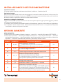
INSTALLAZIONE E SOSTITUZIONE BATTERIE
Installazione batteria
Il Cronotermostato funziona esclusivamente a batterie, installare nr. 2 batterie tipo AA.
Sostituzione batteria
Quando l’icona della batteria scarica inizia a lampeggiare, è necessario sostituire le batterie con due nuove. Per
sostituire le batterie, impostare il sistema su SPENTO, rimuovere il termostato dalla parete, quindi sostituire
le batterie aprendo lo sportellino sulla parte inferiore del termostato.
Istruzioni per cablaggio e installazione
Leggere con attenzione le presenti istruzioni. Il mancato rispetto di queste regole può danneggiare il prodotto
o causare una situazione pericolosa.
1. Verificare il carico massimo previsto dalle istruzioni e dal prodotto per garantire che sia indicato per l’applicazione.
2. Gli installatori devono essere tecnici dell’assistenza idoneamente formati e di esperienza.Completata
l’installazione, attenersi alle presenti istruzioni
ELEMENTI PARAMETRO DESCRIZIONE PARAMETRO PREDEFINITO
02 HA, HE
HA: Riscaldamento a pavimento
e raffrescamento con consenso ventilazione
HE: Riscaldamento e raffrescamento con consenso ventilazione
HA
04 00, 01 0: cambio di stagione manuale
1: cambio di stagione automatico 00
05 1~4.5 Cambio stagione automatico valore della banda neutra 1
10 1, 2, 3
Seleziona retroilluminazione del display:
1: nessuna retroilluminazione del display
2: la retroilluminazione si accende per circa 5 secondi quando
viene premuto qualsiasi pulsante del termostato
2
11 -2~+2 Settaggio della temperatura 0
12 C, F Selezionare modalità °F (Fahrenheit) o °C (Celsius) C
16 00~12
Selezionare la sostituzione del filtro.
Sul termostato apparirà il messaggio “CHG FILTER”, questo è
un promemoria per il cambio e/o la pulizia del filtro dell’aria.
L’ora può essere impostata da 0-12 mesi con incrementi di un
mese. Selezionare 00 per annullare questa funzione.
00
OPZIONI AVANZATE
1. Premi K4 fino (16) a quando il display si spegne ---premi K3--- premi K1, (8), apparirà SET CONFIG ---
2. Premi K2 per accendere --- Ruota k6 per selezionare l’elemento --- premi K1 per confermare --- Ruota K6
per impostare il parametro --- dopo l’impostazione, premi brevemente K1 per tornare indietro all’elemento
impostato --- dopo aver impostato tutti i parametri, premi K3 per salvare e uscire.
MENU PARAMETRI

10
NOTE

11
NOTE

Tecnosystemi S.p.A. Società Benefit
www.tecnosystemi.com
via dell’Industria, 2/4 - Z.I. San Giacomo di Veglia
31029 Vittorio Veneto (Treviso) - Italy
Phone +39 0438.500044 | Fax +39 0438.501516
email: [email protected]
C.F. - P. IVA - R.I.TV IT02535780247
Cap. Soc. € 5.000.000,00 i.v.
W
E
A
R
E
A
B
E
N
E
F
I
T
C
O
M
P
A
N
Y
WATCH OUR
INSTITUTIONAL VIDEO
II
SS
OO
9
9
0
0
0
0
1
1
S
S
Y
Y
S
S
T
T
E
E
MM
CC
EE
RR
TT
II
FF
II
CC
A
A
T
T
I
I
O
O
N
N
800 904474
ONLY FOR ITALY
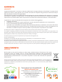
SMALTIMENTO
DISPOSAL
GARANZIA
WARRANTY
Alla fine della sua vita utile il prodotto non deve essere smaltito insieme ai rifiuti urbani. Può essere
consegnato presso gli appositi centri di raccolta differenziata predisposti dalle amministrazioni
comunali, oppure presso i rivenditori che forniscono questo servizio. Per rimarcare l’obbligo di smaltire
separatamente gli elettrodomestici, sul prodotto è riportato il marchio del contenitore di spazzatura
mobile barrato.
At the end of its useful life, the product must not be disposed of with household waste. It can be deposited at
a dedicated recycling centre run by local councils, or at retailers who provide such a service. To highlight the
requirement to dispose of household electrical items separately, there is a crossed-out waste paper basket
symbol on the product.
La garanzia ha durata di 1 (uno) anno a decorrere dalla data di consegna indicata sul d.d.t (bolla). E’ prevista altresì
l’estensione d’ufficio, a titolo gratuito, per il secondo anno (due anni complessivi di garanzia) con decorrenza sempre
dalla data indicata nel d.d.t di consegna (bolla).
L’azienda fornitrice garantisce la qualità dei materiali impiegati e la corretta realizzazione dei componenti. La garanzia
copre difetti di materiale e di fabbricazione e si intende relativa alla fornitura dei pezzi in sostituzione di qualsiasi
componente che presenti difetti, senza che possa venir reclamata alcuna indennità, interesse o richiesta di danni.
La garanzia non copre la sostituzione dei componenti che risultano danneggiati per:
• trasporto non idoneo;
• installazione non conforme a quanto specificato in questo manuale di installazione uso e manutenzione;
• la non osservanza delle specifiche tecniche di prodotto;
• quant’altro non riconducibile a vizi originari del materiale o di produzione a condizione che il reclamo del cliente
sia coperto dalla garanzia e notificato nei termini e modalità richiesta dal fornitore, lo stesso si impegnerà, a sua
discrezione, a sostituire o riparare ciascun prodotto o le parti di questo che presentino vizi o difetti.
The warranty is valid for 2 (two) years from the delivery date indicated on the delivery note / waybill.
The supplier company guarantees the quality of the materials used and the correct construction of the components. The
warranty covers defects in materials and manufacturing defects and refers to the supply of spare parts of any components
featuring defects, without any compensation, interest or claim for damages.
The warranty does not cover the replacement of components damaged due to:
incorrect transportation;
installation not compliant with that specified in this installation, use and maintenance manual;
non-observance of product technical specifications;
Anything else that is not linked to original faults of the material or production provided that the customer complaint is covered
by the guarantee and a claim is made within the time limit and in the way requested by the supplier, the same supplier will
commit, at their own discretion, to replace or repair any product or part of product showing signs of faults or defects.
-
 1
1
-
 2
2
-
 3
3
-
 4
4
-
 5
5
-
 6
6
-
 7
7
-
 8
8
-
 9
9
-
 10
10
-
 11
11
-
 12
12


Tecnosystemi SMART SIRIO programmable thermostat Manuale del proprietario
- Tipo
- Manuale del proprietario
Documenti correlati
-
Tecnosystemi Protective Manuale del proprietario
-
-
-
-
-
-
-
Altri documenti
-
 Radialight SIRIO Guida d'installazione
-
Kyosho HALF 8 GP MINI INFERNO 09 Manuale del proprietario
-
BFT SP3500 Manuale utente
-
-
 Aros NetMan 204 Solar Quick Reference Installation Manual
-
-
Dell Stud Sensor MP2000 Manuale utente
-
CAME TH/700 Guida d'installazione
-

