Tyan S2932 Manuale utente
- Categoria
- Schede madri
- Tipo
- Manuale utente
Questo manuale è adatto anche per

1
Thunder n3600M
///
S2932
Version 1.1
Copyright
Copyright © TYAN Computer Corporation, 2007. All rights reserved. No part of
this manual may be reproduced or translated without prior written consent from
TYAN Computer Corp.
Trademark
All registered and unregistered trademarks and company names contained in
this manual are property of their respective owners including, but not limited to
the following.
TYAN, Thunder n3600M are trademarks of TYAN Computer Corporation.
AMD, Opteron, and combinations thereof are trademarks of AMD Corporation.
AMI, AMI BIOS are trademarks of AMI Technologies.
Microsoft, Windows are trademarks of Microsoft Corporation.
Marvell
®
is a trademark of Broadcom Corporation and/or its subsidiaries.
nVIDIA, nForce are trademarks of NVIDIA Corporation.
Notice
Information contained in this document is furnished by TYAN Computer
Corporation and has been reviewed for accuracy and reliability prior to printing.
TYAN assumes no liability whatsoever, and disclaims any express or implied
warranty, relating to sale and/or use of TYAN products including liability or
warranties relating to fitness for a particular purpose or merchantability. TYAN
retains the right to make changes to product descriptions and/or specifications
at any time, without notice. In no event will TYAN be held liable for any direct or
indirect, incidental or consequential damage, loss of use, loss of data or other
malady resulting from errors or inaccuracies of information contained in this
document.

2
Table of Contents
Check the box contents! Page 3
Chapter 1: Introduction
1.1 Congratulations Page 5
1.2 Hardware Specifications Page 5
Chapter 2: Board Installation
2.1 Board Image Page 8
2.2 Block Diagram Page 9
2.3 Board Parts, Jumpers and Connectors Page 10
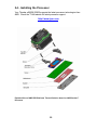
2.4 Installing the Processor Page 22
2.5 Tips on Installing Motherboard in Chassis Page 27
2.6 Installing the Memory Page 28
2.7 Attaching Drive Cables Page 30
2.8 Installing Add-in Cards Page 32
2.9 Connecting External Devices Page 33
2.10 Installing the Power Supply Page 34
2.11 Finishing up Page 35
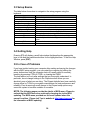
Chapter 3: BIOS Setup
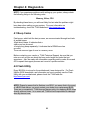
3.1 About the BIOS Page 37
3.2 BIOS Menu Bar Page 37
3.3 Setup Basics Page 38
3.4 Getting Help Page 38
3.5 In Case of Problems Page 38
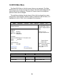
3.6 BIOS Main Menu Page 39
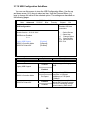
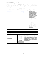
3.7 Advanced Menu Page 40
3.8 PCI PnP Menu Page 62
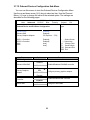
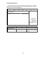
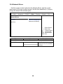
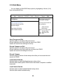
3.9 Boot Menu Page 64
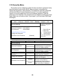
3.10 Security Menu Page 69
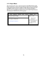
3.11 Chipset Menu Page 70
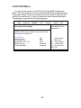
3.12 Exit Menu Page 80
Chapter 4: Diagnostics
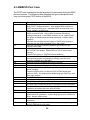
4.1 Beep Codes Page 81
4.2 Flash Utility Page 81
4.3 AMIBIOS Post Code
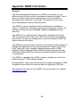
Appendix: SMDC Information
Page 82
Page 85
Glossary Page 87
Technical Support Page 93

3
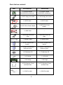
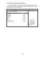
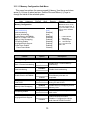
Check the box contents!
Item S2932WG2NR S2932G2NR
1x Thunder n3600M
S2932WG2NR motherboard
1x Thunder n3600M
S2932G2NR motherboard
1x 34-Pin floppy drive cable
1x 34-Pin floppy drive cable
6 x SATA cable 6 x SATA cable
3 x SATA Drive Power Adapter
3 x SATA Drive Power
Adapter
2 x SAS Cable --
1 x Ultra-DMA-100/66 IDE
cable
1 x Ultra-DMA-100/66 IDE
cable
1 x USB2.0 cable 1 x USB2.0 cable
1 x Thunder n3600M user’s
manual
1 x Thunder n3600M user’s
manual
1 x Thunder n3600M Quick
Reference guide
1 x Thunder n3600M Quick
Reference guide
1 x TYAN driver CD 1 x TYAN driver CD
1 x I/O shield 1 x I/O shield
1 x SLI bridge 1 x SLI bridge
2 x CPU Retention Frame
and Back Plate
2 x CPU Retention Frame
and Back Plate
1 x COM Port cable 1 x COM Port cable

4
NOTE

5
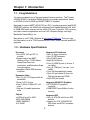
Chapter 1: Introduction
1.1 - Congratulations
You have purchased one of the most powerful server solutions. The Thunder
n3600M (S2932) is a flexible AMD64 platform for multiple applications, based
on NVIDIA nForce Pro3600 and SMSC DME5017 chipsets.
Designed to support AMD
®
uPGA 1207-pin ZIF L1 socket processors and 64GB
DDRII-667 memory, the S2932 with integrated Dual Gigabit Ethernet LAN, built-
in 32MB DDR video memory and six serial ATA ports, is ideal for CPU, memory,
and video intensive applications such as CAD, Graphics Design, and High
Bandwidth Video Editing, etc.
Remember to visit TYAN’s Website at http://www.TYAN.com
. There you can
find information on all of TYAN’s products with FAQs, online manuals and BIOS
upgrades.
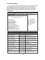
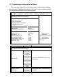
1.2 - Hardware Specifications
Processor
•Two uPGA 1207-pin ZIF L1
sockets
•Supports up to two AMD
Opteron
TM
Rev. F 2000 Series
Santa Rosa Dual core
processors, and Barcelona Quad
core processors
•Integrated 128-bit DDR memory
controller
Expansion Slots
•Two (2) x16 PCI Express with x8
bandwidth
•Three (3) PCI-X slots
•One (1) 32-bit, 33MHz PCI v2.3
slots
•Total six (6) usable expansion
slots
Chipset
•nVIDIA nForce Pro 3600
•NEC nPD720400
•SMSC DME5017
•LSI 1068E
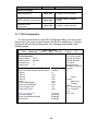
Integrated I/O Interfaces
• One (1) floppy connector
• One (1) IDE connector
• Six (6) SATA ports
• Eight (8) SAS ports
• Four (4) USB2.0 ports (2 at rear, 2
via cable)
• Two (2) COM port (1 at rear, 1 via
cable)
• Tyan 2x9 front-panel pin header
• Tyan 2x7 pin header (2.0mm) for
FAN tachometer and PWM
• 2x25 IPMI pin header
Integrated 2D/3D PCI Graphics
• ATI ES1000 PCI graphics
controller
• 32MB DDR Frame Buffer of video
memory
Integrated IDE
• One (1) ATA IDE slot for two IDE
devices
• Support for ATA-133/100/66/33
IDE drives and ATAPI compliant
devices

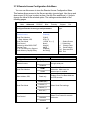
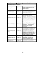
6
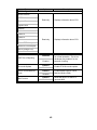
System Management
• SMSC DME5017 w/ hardware
monitoring
• Seven 4-pin fan header
• Temperature and voltage
monitoring
• Watchdog timer
• Port 80 code display LED
• TYAN IPMI support
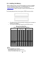
Memory
• Dual memory channels
• Supports up to 16 DDRII-667
DIMMs
• Up to 64GB of register ECC/non-
ECC memory
Integrated Serial ATA II
•Serial ATA Host controllers
embedded
•Supports six serial ports running at
3.0Gb/s
•NV RAID 0, 1, 0+1, 5 and JBOD
support
•SATA activity LED connector
Serial Attached SCSI(SAS)
•LSI 1068E PCI-E SAS controller
•Supports 8 SAS ports running at
3.0Gb/s
•RAID 0, 1 and JBOD support
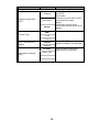
Back Panel I/O Ports
•Stacked PS/2 mouse & keyboard
ports
•Two (2) USB 2.0 ports
•One (1) COM1 connector
•One (1) 15-pin VGA port
•Two RJ45 (Marvell 88E1121 PHy
+ nVIDIA MAC) 10/100/1000
Base-T port with link/activity LED
Integrated LAN Controllers
•Two 10/100/1000 Base-T LAN
(nForce Pro3600 integrated MAC
with Marvell 88E1121Gigabit
Ethernet PHY)
•IEEE802.3 compliant, WOL/PXE
support
BIOS
•AMI BIOS 8Mbit Flash
•Supports ACPI 2.0
•PnP, DMI2.0, WfM2.0 power
management
Power
•ATX12V support, on-board 4-
phase VRD
•Universal 24-pin + 8-pin power
connectors
•4-pin auxiliary power connector
Form Factor
•Extended ATX (13” x 12”)
•8 layers PCB
Regulatory
•FCC Class B (Declaration of
Conformity)
•CE (Declaration of Conformity)
PCI-E Assignment
•X16 PCI Express with x8
bandwidth
•X16 PCI Express with x8
bandwidth
•NEC nPD720400 with x4
bandwidth
•LSI 1068E with x8 bandwidth

7
Chapter 2: Board Installation
You are now ready to install your motherboard. The mounting hole pattern of
the Thunder n3600M S2932 matches the EATX specification. Before continuing
with installation, confirm that your chassis supports an ATX motherboard.
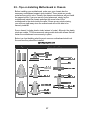
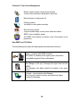
How to install our products right… the first time
The first thing you should do is reading this user’s manual. It contains important
information that will make configuration and setup much easier. Here are some
precautions you should take when installing your motherboard:
(1) Ground yourself properly before removing your motherboard from the
antistatic bag. Unplug the power from your computer power supply and
then touch a safely grounded object to release static charge (i.e. power
supply case). For the safest conditions, TYAN recommends wearing a
static safety wrist strap.
(2) Hold the motherboard by its edges and do not touch the bottom of the
board, or flex the board in any way.
(3) Avoid touching the motherboard components, IC chips, connectors,
memory modules, and leads.
(4) Place the motherboard on a grounded antistatic surface or on the
antistatic bag that the board was shipped in.
(5) Inspect the board for damage.
The following pages include details on how to install your motherboard into your
chassis, as well as installing the processor, memory, disk drives and cables.
NOTE
DO NOT APPLY POWER TO THE BOARD IF IT HAS BEEN
DAMAGED.

8
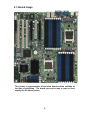
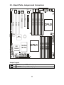
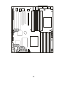
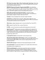
2.1- Board Image
This picture is representative of the latest board revision available at
the time of publishing. The board you receive may or may not look
exactly like the above picture.

9
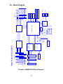
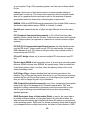
2.2 - Block Diagram
Thunder n3600M S2932 Block Diagram
DDR2 SDRAM 5
DDR2 SDRAM 7
DDR2 SDRAM 4
DDR2 SDRAM 6
DDR2 SDRAM 3
DDR2 SDRAM 5
Dual Socket F(LGA1207)
DDR2 SDRAM 7
DDR2 SDRAM 4
DDR2 SDRAM 6
Channel B
DDR2 SDRAM
Interface
PCI-X slot
GBLAN
GBLAN
PCI-X slot
RJ45
RJ45
88E1121
DDR2 SDRAM
Interface
Channel A
16 x 16
HyperTransport
IDE * 1
MCP55 Pro
RegisteredRegistered
AMD Socket F
Processor
CPU2
AMD Socket F
Processor
CPU1
PCI-E X8 (X16 Slot)
PCI-E X8 (X16 Slot)
uPD720400
DDR2 SDRAM 0
DDR2 SDRAM 1
DDR2 SDRAM 2
DDR2SDRAM 3
USB * 4
SATA * 6
PCI-X 64/133
DDR2 SDRAM
Interface
DDR2 SDRAM
Interface
Channel A
Channel B
DDR2 SDRAM 2
DDR2 SDRAM 1
PCI-Express X8
DDR2 SDRAM 0
Secondary CPU Primary CPU
PCI-X slot
Channel A
Channel B
NEC
S1 S2 P1
16 x 16
HyperTransport
Marvell
BIOS
Super IO
SCH5017
FLOPPY
COM1
COM2
KB/MS
PCI-Express X4
SAS1068E
LSI
PCI 32/33
PCI slot
VGA
ATI ES1000
PCI Bus
SAS * 8
LPC
RGMII
L1
L1
L0

10
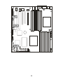
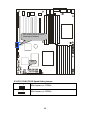
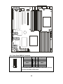
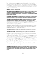
2.3 - Board Parts, Jumpers and Connectors
CPU2_DIMM0
CPU2_DIMM1
CPU2_DIMM2
CPU2_DIMM3
CPU2_DIMM4
CPU2_DIMM5
CPU2_DIMM6
CPU2_DIMM7
CPU1_DIMM0
CPU1_DIMM1
CPU1_DIMM2
CPU1_DIMM3
CPU1_DIMM4
CPU1_DIMM5
CPU1_DIMM6
CPU1_DIMM7
PW1
PW3
PW2
CPU1
CPU2
PCI-E1
PCI
KB/MS
USB1
COM1
USB1
VGA
LAN2
LA N 1
CPUFAN2
PCI-E1PCI-E1
PCI-E2
PCIX-P1
PCIX-S1
PCIX-S2
J10
J8
J17
J18
JP1
JP2
JP3
JP4
JP5
JP6
J38
J39
J41
FAN 3
FAN 4
SAS0
SA S1
SAS2
SAS3
SAS4
SAS5
SA S6
SA S7
J63
J64
J65
J66
J61
SATA0
S ATA 1
SATA2
SATA 3
SATA4
SATA5
CP UFAN1
FAN1
FAN2
BIOS
ATI
ES1000
ATI
ES1000
SMSC
SC H50 17
32 MB
DDR
Ma rve l l
88E112 1
FAN5
J67
NV IDI A
MCP55
LSI
1068E
NEC
UPD720400CFF
JP7
Jumper Legend
OPEN - Jumper OFF, without jumper cover
CLOSED – Jumper ON, with jumper cover

11
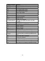
Jumper/Connector Function
JP1/JP2 PCI-S1/ PCI-S2 Speed Setting Jumper
JP3/JP4 SMDC Select Jumper
JP5 VGA Enable/Disable Jumper
JP6 SAS Enable/Disable Jumper
JP7 Clear CMOS Jumper
J1 Keyboard/Mouse Connectors
J2 VGA Connector
J3 COM Port Connector
J4/J5 Gigabit LAN Port
J7/J42/J43/J59/J62
Chassis Fan Connectors
J59: FAN1, J62: FAN2, J42: FAN3, J43: FAN4
J7: FAN5
J8 COM Port Pin Header
J9/J55 J55: CPUFAN1; J9: CPUFAN2 connectors
J10 Floppy Connector
J17 SMDC Connector
J18 IPMB Pin Header
PW1/PW2/PW3 Power Connectors (see p.34 for details)
J38 LCM Pin Header (for Barebone use only)
J39/J63
TYAN Front Panel 2 Connector (for Barebone use
only)
J41 Front Panel USB2.0 Connectors
J61 Primary IDE Connector
J64 Front Panel Header
J65 SGPIO Header (for Barebone use only)
J66 SAS Fault LED Pin Header (for Barebone use only)

12
J18
J64
J17

13
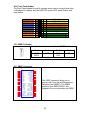
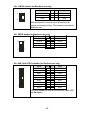
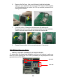
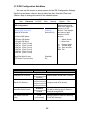
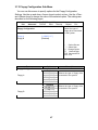
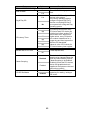
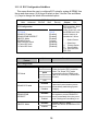
J64: Front Panel Header
The Front Panel Header is used to connect some control or signal wires from
motherboard to chassis, such as HDD LED, power LED, power button, and
reset button.
J18: IPMB Pin Header
1
Use this header to connect to the IPMB device.
Pin 1 Pin 2 Pin 3 Pin 4
IPMB
DATA
GND IPMB
CLK
NC
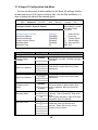
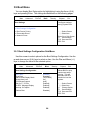
J17: SMDC Connector
J33
CON25X2_M3291
1
3
5
7
9
11
13
15
17
19
21
23
25
27
29
31
33
35
37
41
43
45
47
49
2
4
6
8
10
12
14
16
18
20
22
24
26
28
30
32
34
36
38
40
44
46
48
50
LAD0
LAD2
GND1
GND2
GND3
GND4
I2C1DA
I2C4CLK
GND6
I2C3DA
I2C2CLK
5VSB2
PWRBTN#
RSTBTN#
OEMBTN#
EXTSMI#
CPUNMI#
SIO_RXD
SIO_TXD
SIO_RTS#
SIO_CTS#
SERIRQ
GND12
SMALERTB#
LAD1
LAD3
LFRAME#
PCI_CLK
PCIRST#
I2C1CLK
GND5
I2C4DA
I2C3CLK
5VSB1
I2C2DA
GND7
PCIPME#
COM_TXD
COM_RXD
SOL_CTRL
GND8
COM_RTS#
COM_CTS#
SYSPWRGD
OEMGPIO
BMC_RST#
SMALERTA#
BMC_DET#
The SMDC connector allows you to
connect with Tyan Server Management
Daughter Card (SMDC). The S2932
supports Tyan SMDC M3291. See
Appendix for more information on SMDC.
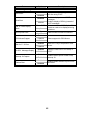
HDD LED+ 1 2 PWR LED+
HDD LED- 3 4 PWR LED-
Reset Switch 5 6 PWR Switch
Reset Switch 7 8 Power Switch
NMI 9 10 Warning LED+
NMI 11 12 Warning LED-
5VSB 13 14 key
SMBus Data 15 16 GND
SMBus Clock 17 18 Chassis Intrusion

14
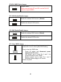
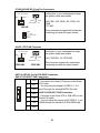
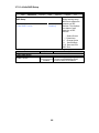
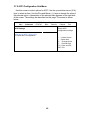
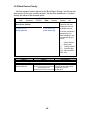
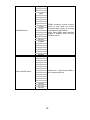
JP1/JP2: PCI-S1/PCI-S2 Speed Setting Jumper
3
1
Max frequency is 133MHz
1
3
Max frequency is 100MHz
JP1/JP2/JP3/JP4/JP5/JP6
(from top to bottom)
JP7

15
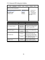
JP3/JP4: SMDC Select Jumper
1
3
Support SMDC.
Please note that both JP3 and JP4 must be Pin #2-3
closed to support SMDC.
JP5: VGA Enable/Disable Jumper
3
1
Enable the onboard VGA function. (Default)
1
3
Disable the onboard VGA function.
JP6: SAS Enable/Disable Jumper
3
1
Enable the onboard SAS function. (Default)
1
3
Disable the onboard SAS function.
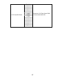
JP7: Clear CMOS Jumper
1
3
Normal
(Default)
3
1
Clear
Use this jumper when you forgot your system/setup
password or need to clear system BIOS setting.
How to clear the CMOS data
- Power off system and disconnect power
supply from AC source
- Use jumper cap to close Pin_2 and 3 for
several seconds to Clear CMOS
- Replace jumper cap to close Pin_1 and 2
Reconnect power supply to AC source
Power on system

16
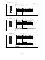
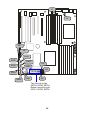
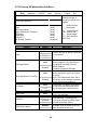
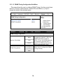
J41: Front Panel USB2.0 Connector
9 10
1
2
Signal Pin Pin Signal
USB PWR 1 2 USB PWR
USB1- 3 4 USB2-
USB1+ 5 6 USB2+
GND 7 8 GND
Key
9 10
GND
Use these headers to connect to the USB devices
via the enclosed USB cable.
J41
J8
J39
J63

17
J8: COM Port Pin Header
9 10
1
2
Use these pin definitions to connect a port to COM2.
*TYAN does not provide cable for this header. It is
designed for OEM use only.
Signal Pin Pin Signal
DCD 1 2 DSR
RXD 3 4 RTS
TXD 5 6 CTS
DTR 7 8 RI
GND
9 10
Key
J39: TYAN Front Panel 2 Connector (for Barebone use only)
11 12
1
2
Signal Pin Pin Signal
LAN1 LED+ 1 2 LAN1 LED-
LAN2 LED+
3 4
LAN2 LED-
NC
5 6
NC
ID LED+ 7 8 ID LED-
ID S/W+
9 10
ID S/W-
Key 11 12 NC
Use this header to connect to the front panel of
barebone.
J63: TYAN Fron Panel 2 Connector (for Barebone use only)
12
13
14
Signal Pin Pin Signal
TACH1 1 2 TACH6
TACH2
3 4
TACH7
TACH3
5 6
TACH8
TACH4
7 8
TACH9
TACH5 9 10 TACH10
GND 11 12 Key
GND
13 14
PWM
Use this header to connect to the front panel of
barebone.

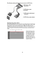
18
J66
J65
J38

19
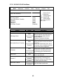
J38: LCM Pin Header (for Barebone use only)
5
1
6
2
5
1
Use
this header to connect the LCM module with
system monitoring function. This header is reserved for
barebone use.
Signal Pin Pin Signal
VCC5V
1 2
RXD2
Key
3 4
GND
5VSB
5 6
TXD2
J65: SGPIO Header (for Barebone use only)
1
2
78
Signal Pin Pin Signal
SDATA_OUT0
1 2
SDATA_IN0
SCLOCK 3 4 SLOAD
SDATA_OUT1
5 6
SDATA_IN1
GND 7 8 Key
J66: SAS Fault LED Pin Header (for Barebone use only)
1
2
17
18
Signal Pin Pin Signal
SAS0+ 1 2 SAS0-
SAS1+
3 4
SAS1-
SAS2+ 5 6 SAS2-
SAS3+
7 8
SAS3-
Key 9 10 NC
SAS4+ 11 12 SAS4-
SAS5+ 13 14 SAS5-
SAS6+
15 16
SAS6-
SAS7+
17 18
SAS7-
Use this header to connect to the SAS Fault LED
on Barebone.

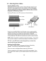
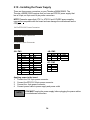
20
J59
J42
J55
J9
J62
SAS5
SAS2
SAS3
SAS0
SAS1
J43
J7
SAS6
SAS7
Top: from left to right
SATA0, SATA2, SATA4
Bottom: from left to right
SATA1, SATA3, SATA5
SAS4
La pagina si sta caricando...
La pagina si sta caricando...
La pagina si sta caricando...
La pagina si sta caricando...
La pagina si sta caricando...
La pagina si sta caricando...
La pagina si sta caricando...
La pagina si sta caricando...
La pagina si sta caricando...
La pagina si sta caricando...
La pagina si sta caricando...
La pagina si sta caricando...
La pagina si sta caricando...
La pagina si sta caricando...
La pagina si sta caricando...
La pagina si sta caricando...
La pagina si sta caricando...
La pagina si sta caricando...
La pagina si sta caricando...
La pagina si sta caricando...
La pagina si sta caricando...
La pagina si sta caricando...
La pagina si sta caricando...
La pagina si sta caricando...
La pagina si sta caricando...
La pagina si sta caricando...
La pagina si sta caricando...
La pagina si sta caricando...
La pagina si sta caricando...
La pagina si sta caricando...
La pagina si sta caricando...
La pagina si sta caricando...
La pagina si sta caricando...
La pagina si sta caricando...
La pagina si sta caricando...
La pagina si sta caricando...
La pagina si sta caricando...
La pagina si sta caricando...
La pagina si sta caricando...
La pagina si sta caricando...
La pagina si sta caricando...
La pagina si sta caricando...
La pagina si sta caricando...
La pagina si sta caricando...
La pagina si sta caricando...
La pagina si sta caricando...
La pagina si sta caricando...
La pagina si sta caricando...
La pagina si sta caricando...
La pagina si sta caricando...
La pagina si sta caricando...
La pagina si sta caricando...
La pagina si sta caricando...
La pagina si sta caricando...
La pagina si sta caricando...
La pagina si sta caricando...
La pagina si sta caricando...
La pagina si sta caricando...
La pagina si sta caricando...
La pagina si sta caricando...
La pagina si sta caricando...
La pagina si sta caricando...
La pagina si sta caricando...
La pagina si sta caricando...
La pagina si sta caricando...
La pagina si sta caricando...
La pagina si sta caricando...
La pagina si sta caricando...
La pagina si sta caricando...
La pagina si sta caricando...
La pagina si sta caricando...
La pagina si sta caricando...
La pagina si sta caricando...
La pagina si sta caricando...
-
 1
1
-
 2
2
-
 3
3
-
 4
4
-
 5
5
-
 6
6
-
 7
7
-
 8
8
-
 9
9
-
 10
10
-
 11
11
-
 12
12
-
 13
13
-
 14
14
-
 15
15
-
 16
16
-
 17
17
-
 18
18
-
 19
19
-
 20
20
-
 21
21
-
 22
22
-
 23
23
-
 24
24
-
 25
25
-
 26
26
-
 27
27
-
 28
28
-
 29
29
-
 30
30
-
 31
31
-
 32
32
-
 33
33
-
 34
34
-
 35
35
-
 36
36
-
 37
37
-
 38
38
-
 39
39
-
 40
40
-
 41
41
-
 42
42
-
 43
43
-
 44
44
-
 45
45
-
 46
46
-
 47
47
-
 48
48
-
 49
49
-
 50
50
-
 51
51
-
 52
52
-
 53
53
-
 54
54
-
 55
55
-
 56
56
-
 57
57
-
 58
58
-
 59
59
-
 60
60
-
 61
61
-
 62
62
-
 63
63
-
 64
64
-
 65
65
-
 66
66
-
 67
67
-
 68
68
-
 69
69
-
 70
70
-
 71
71
-
 72
72
-
 73
73
-
 74
74
-
 75
75
-
 76
76
-
 77
77
-
 78
78
-
 79
79
-
 80
80
-
 81
81
-
 82
82
-
 83
83
-
 84
84
-
 85
85
-
 86
86
-
 87
87
-
 88
88
-
 89
89
-
 90
90
-
 91
91
-
 92
92
-
 93
93
-
 94
94


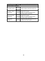
Tyan S2932 Manuale utente
- Categoria
- Schede madri
- Tipo
- Manuale utente
- Questo manuale è adatto anche per
in altre lingue
- English: Tyan S2932 User manual
Documenti correlati
-
Tyan S2881 Manuale utente
-
-
-
-
-
-
-
-
-
Altri documenti
-
Intel AXXRMS2LL080 Hardware User's Manual
-
Gamdias AEOLUS M1 1205R Manuale utente
-
Biostar NF520-A2G Manuale utente
-
Manhattan 151009 Manuale utente
-
ESD I.2306.08 Manuale del proprietario
-
Nvidia JETSON TX1 Quick Start Manuals
-
urmet MK 1051-204 Manuale utente
-
Videotec VD Manuale del proprietario
-
 ESD electronic I.2001.02 Manuale del proprietario
-
Riello NexAqua 80 Plus Manuale utente
