
Product Information
Model
FA10i and FA10i-CE
(-CE compliant with European Directives)
(Dwg. MHP2947)
Save These Instructions
Form MHD56439
Edition 2
March 2010
45899812
© 2010 Ingersoll-Rand Company

Only allow Ingersoll Rand trained technicians to perform maintenance on this product. For additional information contact Ingersoll Rand factory or nearest
Distributor.
For additional supporting documentation refer to Table 1 ‘Product Information Manuals’ on page 2.
Manuals can be downloaded from www.ingersollrandproducts.com.
The use of other than genuine Ingersoll Rand replacement parts may result in safety hazards, decreased performance and increased maintenance and will invalidate all warranties.
The original language of this manual is English.
Refer all communications to the nearest Ingersoll Rand Office or Distributor.
Table 1: Product Information Manuals
Publication Part/Document Number Publication Part/Document Number
Product Safety Information Manual (Non-Man Rider) MHD56250 Product Maintenance Information Manual MHD56401
Product Parts Information Manual MHD56400
PRODUCT DESCRIPTION
Infinity series winches are air powered, planetary geared units designed for and
intended for use as utility winches, with a Mechanism Classification of M5. They shall
not be used for lifting or moving personnel. They may be used to pull or lift loads at
various wire rope take-off angles. Winches can be equipped, with either an internal
automatic disc brake, a manual or automatic band brake, or a combination of both
disc and band brake.
The output from an externally mounted piston air motor is transmitted through a
coupling and shaft to the planetary reduction gear assembly. Output from the
planetary reduction gear assembly is connected to the wire rope drum through the
output shaft.
The disc brake assembly consisting of friction plates splined to a hub which in turn
is connected to the drive shaft from the air motor. Brake friction plates are clamped
to the drum shaft through a spring applied piston. The brake remains applied until
the winch control valve is operated and winch pay out or haul-in occurs. Air is
introduced into a chamber, which is formed between brake piston and brake housing,
causing the brake piston to react, compressing brake springs and releasing friction
plates allowing motor shaft to rotate. A power failure or sudden loss of air will
immediately cause the spring applied brake to engage. The band brake operates by
applying a friction force between brake band and winch drum. The manual band brake
requires an operator to rotate a hand wheel located at side of band brake. The
automatic band brake operation is similar to disc brake operation; they are both fully
disengaged in the haul-in and payout direction.
The design life of the winch is based on the application. Refer to ‘Maintenance
Intervals’ chart in Product Maintenance Information Manual. At the completion of
the specified maintenance intervals, the winch should be subjected to a complete
inspection by an Ingersoll Rand trained technician for determination of remaining
service life.
CE winches in addition to the above have drum guard, upper and lower limit switches,
overload protection and emergency stop as standard features, and are compliant with
CE directives.
2 Form MHD56439 Edition 2

SPECIFICATIONS
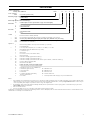
Model Code Explanation
Example: FA10i-36MK320P FA10i - 36 M K 320 P
Series (Capacity):
FA10i
=
22,000 lbs (10 metric tons)
Drum Flange Height or Man Rider™:
-
=
Standard flange
MR = Man Rider™ †
Drum Length (Distance between drum flanges):
36
=
Standard (Refer to Table 3 ‘Specifications’ on page 4 for drum lengths)
Drum Brake:
A = Automatic Band Brake
M =
Manual Band Brake
X = None
Disc Brake:
K
=
Automatic Disc Brake
X = None
Control:
1
=
Winch mounted lever throttle (Standard)
* 2XX = Remote full flow lever throttle [XX = Specify hose length (feet). Maximum 20 ft. (6 metres)]
* 3XX
=
Remote pilot pendant throttle [XX = Specify hose length (feet). Maximum 66 ft. (20 metres)]
* 4XX = Remote pilot lever throttle [XX = Specify length (feet). Maximum 66 ft. (20 metres)]
* 5XXX = Remote electric over air throttle †
Options: **
7 = Drum Grooving (Number = wire rope size in sixteenths, e.g. 7/16 inch) †
B = Extended Warranty
** C = Low Temperature Components; C1 = -20° ABS, C2 = -20° DNV, C3 = -20° LRS
D = Drum Divider Flange and additional wire rope anchor †
E = Construction Cage †
G = Drum Guard
J = Air Line Accessories (not mounted to winch)
L = Drum Locking Pin
** M1 = Material Traceability (typical material results) ††
** M2 = Material Traceability (actual material results) ††
** M3 = Material Traceability (actual material results for these parts in finished, as-delivered condition) ††
N1 = American Bureau of Shipping (ABS)
N2 = Det Norske Veritas (DNV)
P =
Marine 812 Grade Corrosion Preventative Finish
P1 = Marine 812-X Grade Corrosion Preventative Finish
Q = Adjustable Accu-Spool™ (refer to MHD56390) †
S = Limit Switch (upper and lower) W1 = ABS witness test
T = Tensioning System W2 = DNV witness test
U = Underwound W3 = LRS witness test
-CE =
Compliance with European Machinery
Directive and EN 14492–1
W4 = Customer witness test
V = Press Roller Y = Overload protection with emergency stop on lever throttle valve
Notes:
* Remote throttles are provided with 6 feet (2 metres) of hose. Specify hose lengths greater than 6 feet. For lengths greater than 20 feet (6 metres) with the remote
full flow throttle, or 66 feet (20 metres) with the remote pilot lever and remote pilot pendant throttles, contact your Ingersoll Rand distributor or the factory for
control acceptability. Metric lengths are provided for reference only, order lengths in feet.
** Documentation, witness testing and material traceability available; must be requested at time of order. Specify options or contact the factory or your nearest
Ingersoll Rand distributor for information.
† Not covered in this manual.
†† Refer to ‘Traceability’ on page 4 for a description of the differences between M1, M2 and M3.
All -E models are manufactured to previous European Machinery directives. Refer to Data (Name) Plate on winch to determine model. If winch is a custom build also refer to
the Declaration of Conformity for serial number break.
Form MHD56439 Edition 2 3

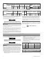
Table 2: Specifications
Models
Air System Rated Performance (at rated pressure/volume)
Rated Operating
Pressure
Air Consumption
(at rated pressure
and load)
Full Drum
Line Pull
Full Drum
Line Speed
Max Stall Pull,
First Layer
Force
Limit
Factor
Maximum
Freeboard
Net Weight **
scfm cu.m/min Lbs Kgs fpm m/min lbs kgs inch mm lbs kgs
FA10i
90 psig (630 kPa / 6.3
bar)
800 22.7 22000 10000 23 7 52650 23880
N/A 1/2 13 3500 1588
FA10i-CE
1.6 2.2 56 3720 1687
** Weight of standard winch without wire rope
Table 3: Specifications
Models
Drum Barrel Size
Drum Flange
Diameter
Recommended
Wire Rope Size
Sound
Pressure
Level
Sound
Power
Level
Maximum Foundation
Anchor Shear Force At One
Capscrew
Air Motor Pipe
Inlet Size
Minimum Air
System Hose
Size (inside
diameter)
inch mm inch mm inch mm Lbs N inch mm inch mm
FA10i &
FA10i-CE
20 508 38 965 1-1/8 28 101 113 3655 16260 1.25 32 1.50 38
Sound measurements have been made in accordance with ISO 11201, ISO 3744-3746
and ISO 4871 test specifications for sound from pneumatic equipment. Readings
shown are based on the average noise level of each winch configuration,
proportionate to the utilized time in a regular cycle.
Lpc (Peak Sound Pressure) does not exceed 130 dB. Performance based on 90 psig
(6.3 bar/630 kPs) operating pressure.
NOTICE
• All -E winch models are manufactured to previous European Machinery
directives. Refer to Data (Name) Plate on winch to determine model. If winch
is a custom build also refer to the Declaration of Conformity for serial number
break.
n
Traceability
Load bearing parts are documented to provide traceability. Documentation includes
chemical and physical properties of raw material, heat treating, hardening, tensile
and charpy tests as required for the part.
Units with M1, M2 or M3 in the model code have traceable load bearing components.
M1 – Material Traceability certificates according to EN 10204 (Ex DIN 50049) 2.2 on
load bearing parts. Conformity documents affirm (by the manufacturer) that parts are
in compliance with requirements of the order, based on non-specific inspection and
testing (i.e. results are typical material properties for these parts).
M2 – Material Traceability certificates according to EN 10204 (Ex DIN 50049) 3.1b on
load bearing parts. Conformity documents affirm (by a department independent of
the manufacturing department) that actual parts are in compliance with requirements
of the order, based on specific inspection and testing (i.e. results are actual material
properties for these parts).
M3 – Material Traceability certificates according to EN 10204 (Ex DIN 50049) 3.1b on
load bearing parts. Conformity documents affirm (by a department independent of
the manufacturing department) that the actual parts used in the product are in
compliance with the order, based on specific inspection and testing (i.e. results are
actual material properties for these parts in a finished, as delivered condition).
Components with part numbers ending in CH are charpy parts for use under extreme
cold conditions. Traceability requirements must be stated when reordering these parts
for continued certification.
n
ATEX
Refer to labeling on product, located near or on data (name) plate, for specific ATEX
designation. Product not marked as such, are not suitable for use in any potentially
explosive atmosphere (ATEX). Refer to Product Safety and Maintenance Information
Manuals for further explanation.
II 2 GD c IIB 200°C X
(Dwg. MHP2584)
INSTALLATION
Prior to installing the product, carefully inspect it for possible shipping damage.
Products are supplied fully lubricated from the factory. Check oil levels and adjust as
necessary before operating product. Refer to “LUBRICATION” section on page 8
for recommended oils and lubrication intervals.
CAUTION
• Owners and users are advised to examine specific, local or other regulations,
including American National Standards Institute and/or OSHA Regulations
which may apply to a particular type of use of this product before installing
or putting product to use.
NOTICE
• Prior to installation refer to Product Safety Information Manual for all
sections of installation.
n
Mounting
Care must be taken when moving, positioning or mounting the winch. In most cases,
lifting lugs have been provided to assist in handling the winch. If lug locations are
improper for your specific installation, great care should be taken to ensure that
winch, when lifted, will be properly balanced. Determine weight of your winch by
referring to “SPECIFICATIONS” section on page 3. Add weight of wire rope and other
installed options as necessary. Lift winch 3 to 4 inches (75 to 100 mm) off ground.
Verify winch is balanced and secure before continuing lift. Mount winch so axis of
drum is horizontal and that motor vent cap is not more than 15° off top vertical
center. If winch is to be mounted in an inverted position, motor case must be rotated
to position vent cap to the top.
1. The winch mounting surface must be flat and of sufficient strength to handle
rated load plus weight of winch and attached equipment. An inadequate
foundation may cause distortion or twisting of winch uprights and siderails
resulting in winch damage.
2. Make sure mounting surface is flat to within 0.005 inch (0.127 mm) per inch of
drum length. Shim if necessary. Refer to Table 4 ‘Mounting Surface Tolerance’
on page 4.
3. Mounting bolts must be Grade 8 or better. Use self-locking nuts or nuts with
lockwashers. Refer to Table 5 ‘Mounting Bolts’ on page 4.
4. Tighten mounting bolts evenly and torque to specification in torque chart. Refer
to ‘TORQUE CHART’ in Product Maintenance Manual.
5. Maintain a fleet angle between sheave and winch of no more than 1-1/2°. The
lead sheave must be on a center line with drum and, for every inch (25 mm) of
drum length, be at least 1.6 feet (0.5 metre) from the drum. Refer to Product
Safety Information Manual.
6. Do not weld to any part of winch.
Table 4: Mounting Surface Tolerance
Drum Length Mounting Surface Minimum Flatness
inch mm inch mm
24 610 0.12 3.05
30 762 0.15 3.81
36 914 0.18 4.57
40 1016 0.20 5.08
50 1270 0.25 6.35
Table 5: Mounting Bolts
Model
Mounting Bolts
inch mm
FA10i
7/8 22
Refer to Dwg. MHP0920 on page 11, A. Drum.
4 Form MHD56439 Edition 2

Table 6: Winch Bolt Hole Mounting Dimensions
Dimension
Drum Length (inches)
24 30 36 40 50
“A”
inch
42.25
mm
1073
“B”
inch
6 8
mm
152 203
“C”
inch
15/16
mm
24
“D” (With Band Brake)
inch
14 12 18 22 32
mm
356 305 457 559 813
“D” (Without Band Brake)
inch
10 8 14 18 28
mm
254 203 356 457 711
n
Wire Rope
CAUTION
• Maintain at least 3 tight wraps of wire rope on the drum at all times.
• Do not use wire rope as a ground (earth) for welding.
• Do not attach a welding electrode to winch or wire rope.
• Install wire rope to come off drum for overwind operation (normal
application).
NOTICE
• For underwound applications order the “U” option or contact factory prior to
operation.
n Wire Rope Selection
Consult a reputable wire rope manufacturer or distributor for assistance in selecting
the appropriate type and size of wire rope and, where necessary, a protective coating.
Use a wire rope which provides an adequate safety factor to handle the actual working
load and meets all applicable industry, trade association, federal, state and local
regulations.
When considering wire rope requirements the actual working load must include not
only the static or dead load but also loads resulting from acceleration, retardation
and shock load. Consideration must also be given to the size of the winch wire rope
drum, sheaves and method of reeving. Maximum wire rope diameter is limited by the
wire rope anchor. It is recommended that wire rope construction be 6 X 19 or 6 X 37
IWRC right lay. Refer to Table 7 ‘Minimum and Maximum Wire Rope Size’
on page 5 for recommended sizes.
Table 7: Minimum and Maximum Wire Rope Size
Model
Minimum Maximum
inch mm inch mm
FA10i
3/4 20 1- 1/8 28
Note 1: Maximum wire rope diameter is limited by size of wire rope anchor hole. Refer
to Product Parts Information Manual for correct wire rope anchor part numbers.
Note 2: Wire rope diameter is fixed if grooved drum option is used.
n Installing Wire Rope
NOTICE
• When installing wire rope, pressurize disc brake with a minimum of 45 psi
(3.1 bar) air from an auxiliary source.
Refer to Dwg. MHP2686 on page 11, A. Anchor; B. Wire Rope.
1. Cut wire rope to length in accordance with wire rope manufacturer’s instructions.
2. Feed end of wire rope through drum anchor pocket hole.
3. Forming a loop, wrap loop around anchor, approximately 22 inches (559 mm) of
wire rope.
4. Pull wire rope anchor into position in drum anchor pocket. Ensure no extra (open
end) of wire rope is extending out of drum anchor pocket.
CAUTION
• Make sure first wrap of wire rope is tight and lays flush against drum flange.
n Safe Wire Rope Handling Procedure
- Always use gloves when handling wire rope.
- Never use wire rope that is frayed or kinked.
- Never use wire rope as a sling.
- Always ensure wire rope is correctly spooled and the first layer is tight against
drum.
- Always follow wire rope manufacturer’s recommendation on use and
maintenance of wire rope.
n
Wire Rope Spooling
To compensate for uneven spooling and the decrease in line pull capacity as the drum
fills up, use as short a wire rope as practical. When rewinding apply tension to the
end of the wire rope to eliminate line slack. This helps achieve level winding and
tight spooling.
n Rigging
Make sure all wire rope blocks, tackle and fasteners have a sufficient safety margin
to handle required load under all conditions. Do not allow wire rope to contact sharp
edges or make sharp bends which will cause damage to wire rope, use a sheave. Refer
to wire rope manufacturer’s instructions for proper sizing, use and care of wire rope.
n Safe Installation Procedures
1. Do not use wire rope as a ground (earth) for welding.
2. Do not attach a welding electrode to winch or wire rope.
3. Never run wire rope over a sharp edge. Use a correctly sized sheave.
4. When a lead sheave is used, it must be aligned with center of drum. The diameter
of lead sheave must be at least 18 times the diameter of wire rope. Refer to Dwg.
MHP2449 in Product Safety Information Manual.
5. Always maintain at least three full, tight wraps of wire rope on drum.
n
Drum Guard
Use of a drum guard is recommended on all winches, and is standard on -CE winches.
Refer to the Product Parts Information Manual.
Drum guard panels must be adjusted to suit wire rope departure angle. To reposition
drum guard panels remove nuts and slide out crossbar. Position panels to avoid wire
rope contact and install crossbar and nuts.
WARNING
• Do not allow wire rope to come in contact with drum guard panels during
winch operation. Wire rope could become worn and damaged. Adjust drum
guard panels to clear wire rope travel angle.
n
Air Supply
The air supply must be clean, free from moisture and lubricated to ensure optimum
motor performance. Foreign particles, moisture and lack of lubrication are the primary
causes of premature motor wear and breakdown. Using an air filter, lubricator and
moisture separator will improve overall product performance and reduce unscheduled
downtime. Refer to Dwg. MHP0191 on page 11, A. Air Out; B. Lubricator; C.
Regulator; D. Air In; E. Filter.
Refer to Table 2 ‘Specifications’ on page 4 for motor air consumption and rated
operating pressure. If air supply varies from what is recommended, product
performance will change.
Install air line lubricator, filter and regulator as close as possible to air inlet on motor.
Lubricator must be located no more than 10 ft (3 m) from motor. Air line accessories
package can also be mounted to the winch guard panel on the operator’s side or
opposite.
n Air Lines
Inside diameter of air supply lines must not be less than size specified in Table 2
‘Specifications’ on page 4. Before making final connections, all air supply lines should
be purged with clean, moisture free air or nitrogen before connecting to main air
inlet. Supply lines should be as short and straight as installation conditions will
permit. Long transmission lines and excessive use of fittings, elbows, tees, globe
valves, etc. cause a reduction in pressure due to restrictions and surface friction in
lines.
n Air Line Lubricator
Always use an air line lubricator with these motors. The lubricator must have an inlet
and outlet at least as large as inlet on motor.
CAUTION
• Lubricator must be located no more than 10 ft (3 m) from motor.
• Shut off air supply before filling air line lubricator.
The air line lubricator should be replenished daily and set to provide 6 to 9 drops per
minute of ISO VG 32 (SAE 10W) oil. A fine mist will be exhausted from control valve
when air line lubricator is functioning properly.
n Air Line Filter
It is recommended that an air line strainer/filter be installed before the lubricator to
prevent dirt from entering the motor. The strainer/filter should provide 20 micron
filtration and include a moisture trap. Clean the strainer/filter periodically to
maintain its operating efficiency.
NOTICE
• When air filter is used ensure it allows air to pass through at products rated
scfm. Refer to “SPECIFICATIONS” on page 3.
n Air Pressure Regulator
If an air pressure regulator is used, install between lubricator and filter.
Form MHD56439 Edition 2
5

NOTICE
• Do not adjust regulator for a CE marked product, these are preset at factory
and pressure gauges are not provided. Adjustment of regulator will effect
overload settings and product will no longer conform to CE regulations.
• Not all products are CE approved, refer to products data (name) plate to see
if this applies.
n Moisture in Air Lines
Moisture that reaches the air motor through air supply lines is a primary factor in
determining the length of time between service overhauls. Moisture traps can help
to eliminate moisture. Other methods, such as an air receiver which collects moisture
before it reaches motor, or an aftercooler at compressor that cools air to condense
and collect moisture prior to distribution through supply lines, are also helpful.
n Mufflers
Ensure mufflers are installed in winch exhaust manifold and control valve exhaust
port. Check mufflers periodically to ensure they are functioning correctly.
n Shut Off Valve
Refer to the Product Safety Information Manual for information.
n
Motor
For optimum performance and maximum durability of parts, provide recommended air
supply as measured at motor inlet. Refer to Table 2 ‘Specifications’ on page 4. The air
motor should be installed as near as possible to compressor or air receiver.
n
Tensioning System (optional feature)
Refer to Dwg. MHP1176 on page 12; A. Payout; B. Motor; C. Haul-In; D. Brake;
E. Check Valve; F. Pressure Gauge; G. Regulator; H. Selector Valve; J. Manual Throttle;
K. Shuttle Valve; L. Quick Exhaust Valve; M. Air Supply.
The air supply line is connected to one of the two top ports on the control valve. This
will allow air to supply either the normal control valve or the auxiliary valve.
WARNING
• Use only one control valve to operate winch at any time. Attempting to
OVERRIDE one control valve with the other will result in total loss of winch
control.
n
Limit Switches
Limit switches are standard on -CE winches.
Pre-set limit switch settings prevent winch wire rope payout and haul-in by stopping
air flow to the winch motor when a defined set point has been reached. It is the
owner’s and operator’s responsibility to adjust winch operating limits prior to using
winch.
NOTICE
• Settings for limit switch are for an overwound operation only.
To adjust set points:
Follow instructions in the order they appear for limit switch adjustment (use two
people to make adjustments). Refer to Dwg. MHP2688 on page 11, A. Center Nut;
B. Payout; C. Haul-In:
1. Remove cap from limit switch cover.
2. Partially unscrew center nut.
3.
PAYOUT: Rotate (#1) screw (counterclockwise) while slowly paying out until
winch shuts off.
4.
HAUL-IN: Rotate (#2) screw (clockwise) while slowly hauling in until winch shuts
off.
5. Tighten center nut.
6. Reinstall cap on limit switch cover and tighten.
WARNING
• Ensure limit switch setpoints are established and operating properly before
putting winch into service.
n
Press Roller (optional feature)
Ensure wire rope is positioned between press roller and drum barrel and springs keep
press roller in tight contact with wire rope.
n
Initial Winch Operating Checks
Winches are tested for proper operation prior to leaving the factory. Before the winch
is placed into service the following initial operating checks should be performed.
1. When first running the motor inject a small amount of light oil into the inlet
connection to provide initial lubrication.
2. Check oil level in motor, reduction gear assembly and disc brake are correct. Top
off levels as required before operation as described in
“LUBRICATION” on page 8.
3. Operate winch in both directions with no load for one to two minutes.
4. New brake band Lining Run-in Procedure: All new brake band linings require a
‘run-in’ period. Operate the winch without load in the payout direction while
gradually applying the brake. Allow the brake to slip for approximately one
minute. Winch motor may stall as drum brake band lining fully engages. Do not
allow brake to overheat.
5. Check operation of brakes. Adjust if necessary as described in “MAINTENANCE”
section in the Product Maintenance Information Manual.
6. Check operation of limit switches, locking mechanisms and all safety devices
when equipped.
7. Check foundation mounting fasteners are secure.
8. Install drum guard when provided.
For winches that have been in storage, the following start-up procedures are required:
1. Give the winch an inspection conforming to requirements of
‘Winches Not in Regular Use’ on page 8.
2. Pour a small amount of ISO VG 32 (SAE 10W) oil in motor inlet port.
3. Operate motor for 15 seconds in both directions to flush out any impurities.
4. The winch is now ready for normal use.
OPERATION
It is recommended that the user and owner check all appropriate and applicable
regulations before placing this product into use. Refer to Product Safety Information
Manual before operating product.
The four most important aspects of product operation are:
1. Follow all safety instructions when operating the product.
2. Allow only people trained in safety and operation of this winch to operate this
equipment.
3. Subject each product to a regular inspection and maintenance procedure.
4. Be aware of product capacity and weight of load at all times.
WARNING
• Do not lift loads over people.
NOTICE
• Refer to Product Parts Information Manual for drawings unless specified
elsewhere.
n
Winch Controls
The spring loaded, motor mounted, live air manual throttle control valve is supplied
as a standard feature on this winch. Optional remote throttle controls are available.
Reference model code on the winch data (name) plate and compare it to
“SPECIFICATIONS” on page 3, to determine your configuration. The throttle controls
provide operator control of motor speed and direction of drum rotation.
n Winch Mounted Air Throttle (standard feature)
Refer to Dwg. MHP1809 on page 11, A. Haul-In; B. Exhaust Port; C. Lift Slider Handle
UP to Unlock; D. Payout; E. Air Inlet Port; F. Brake Release Port.
The winch control throttle valve is spring loaded, full flow air and mounts to the
motor rotary housing.
To operate control valve, place palm of hand on control knob and wrap fingers around
flange of sliding handle. Squeeze fingers, lifting sliding handle up to unlock control
handle. Shift control handle in desired direction to payout or haul-in wire rope. As
viewed from air motor end, move control throttle handle to the right (clockwise) to
payout wire rope and to the left (counterclockwise) to haul-in wire rope. Avoid sudden
movements of handle to ensure smooth operation of winch. When released, handle
will return to neutral or center position, sliding handle will drop down to engage and
lock control handle in place.
n Remote Full Flow Air Throttle (optional feature)
Refer to Dwg. MHP2043 on page 12, A. To Brake; B. Threaded Ports.
6 Form MHD56439 Edition 2

Provides for remote mounting of winch control at a fixed location at up to 20 feet (6
metres) away from winch motor. Air hoses connect throttle to winch motor to provide
winch operation.
Move control throttle handle to the right (clockwise) to payout wire rope and to the
left (counterclockwise) to haul-in wire rope. Avoid sudden movements of control valve
to ensure smooth operation of winch.
n Remote Pilot Pendant Throttle (optional feature)
Refer to Dwg. MHP2398 on page 12, A. Red - Air Supply; B. Green; C. Yellow; D.
Payout load; E. Haul-In Load.
Provides for remote winch control at distances of up to 66* feet (20 metres) away
from winch. The pilot pendant control throttle is a two function movable control
station for winch operation. Pilot pressure from pendant control activates winch
control valve. The winch control valve, located on winch motor, controls motor speed
and direction of drum rotation. Direction of drum rotation is determined by the
pendant lever/button depressed.
n Remote Pilot Lever Throttle (optional feature)
Provides for remote winch control at distances of up to 66* feet (20 metres) away
from winch. The lever pilot control throttle is a fixed mounted lever control station
for winch operation. Pilot pressure from lever pilot control throttle activates winch
control valve. The winch control valve, located on winch motor, controls motor speed
and direction of drum rotation. Direction of drum rotation is determined by the
direction in which lever is shifted.
* For distances greater than 50 feet (15 metres) contact Ingersoll Rand Technical
Sales for control suitability.
n
Underwound Operation (optional feature)
Underwound operation allows wire rope haul-in or payout off the bottom of drum.
This is a special operation and requires a winch specifically designed for this usage.
n
Emergency Stop and Overload System
Emergency Stop and Overload System are standard on -CE winches.
Refer to Dwg. MHP2619 on page 11, A. Emergency Stop Button; B. Push Down to
Stop Winch Movement; C. Overload Valve Reset Button; D. Twist Red Button to Reset;
E. Overload Valve Adjustment Screw.
When emergency stop or overload valve is activated, winch drum rotation will
immediately cease.
CAUTION
• If winch continues to move (payout load) after emergency stop activates,
brake(s) are not holding load and may require adjustment or repair.
When control valve senses a preset pressure difference between ports, a pilot signal
is sent to stop flow of air, winch drum rotation will immediately cease.
n Emergency Stop
Emergency stop device is located on the control valve. When activated, winch drum
rotation will immediately cease. To activate emergency stop, depress (push down)
red palm valve, located on top of control valve.
NOTICE
• If winch overload occurs, overload device, if equipped, also stops winch. To
operate winch after an overload, reduce load and reset overload.
Emergency Stop Reset:
1. Rotate red stop button, in (counterclockwise) direction until red stop button
‘pops’ up.
2. Winch is ready to resume operation.
Pendant Control:
Refer to “Emergency Stop” section and Dwg. MHP1892 on page 12, A. Pendant
Handle; B. “Emergency Stop” Button; C. “ON” Button; D. Winch Control Levers.
n Overload System (CE Models only)
The winch utilizes a direct acting load limiter to limit the maximum line pull to 160%
of the rated line pull. The limiter is a pressure regulator that limits the supply air to
a pressure that will not allow the winch to pull beyond 160% of the rated line pull.
Checking Overload Valve Setting:
Proper test and adjustment of overload should only be performed by an
Ingersoll Rand trained technician. The winch shall not be able to lift a load greater
than 160% of the rated utility load. If this is possible, adjustment is required.
1. Attach load line to a load that is calibrated to maximum rated load for winch.
2. Move control lever to haul-in position. If winch does not lift load, adjust the
adjustment screw. Refer to ‘Overload Valve Adjustment’ in the Product
Maintenance Information Manual.
Setting the Overload:
Attach load line to a load that is calibrated to 160% of winch rated capacity. Shift
control lever to haul-in position.
1. If overload valve activates, reset overload valve. Winch is ready for normal
operation.
2. If winch lifts higher than 160% of rated load, lower load. Turn jam nut
(counterclockwise) in 1/4 turn increments until overload valve activates when
control lever is shifted to haul-in position. After each 1/4 turn, retest winch.
n
Tensioning System (optional feature)
Refer to Dwg. MHP1865 on page 12, A. Pressure Gauge; B. Regulator; C. Auxiliary
Valve (shown in Normal Position); D. Control Valve.
With auxiliary valve in the NORMAL position, winch provides normal operation.
Placing valve selector in TENSIONING position allows winch to automatically operate
to haul-in slack wire rope to maintain tension.
Auxiliary valve provides preset air pressure to air motor and disc brake. This allows
brake to be released and winch to overhaul during TENSIONING operations. In this
position, winch will maintain constant tension on wire rope.
Auxiliary valve is pre-set at zero from the factory. Specific adjustments must be made
in the field. Adjustments can be modified at any time to accommodate the load
conditions. Refer to ‘Regulator Adjustment’ in the Product Maintenance Information
Manual.
n Tensioning System (operation)
1. Place auxiliary valve in NORMAL position.
2. Operate winch normally to position end of load line.
3. Connect load line to load.
WARNING
• Ensure slack load line is taken up by operating winch control valve with
selector in NORMAL position. If selector lever is placed in TENSION position
the winch will immediately attempt to establish line tension causing line to
‘snap’ resulting in injury or damage to property.
4. Operate winch normally to remove slack from load line.
5. Actuate valve to TENSION position to set winch to automatically haul-in load line
and maintain line tension.
n
Winch Brakes
n Manual Drum Band Brake (optional feature)
Manual band brake may be applied by turning brake handwheel (104) to the right
(clockwise) and released by turning handwheel to the left (counterclockwise). Brake
must be kept properly adjusted to hold the required load. Refer to 'Adjustments' in
‟MAINTENANCE” section in Product Maintenance Information Manual for instructions.
n Automatic Drum Band Brake (standard)
The automatic drum band brake is a spring applied, air released brake which utilizes
an air actuated, spring loaded cylinder, that automatically disengages brake when
motor is operated. Air pressure in cylinder overcomes spring pressure to release brake.
When control valve is placed in neutral position, air in cylinder is vented and spring
automatically engages brake to prevent band rotation.
The cylinder clevis must be kept properly adjusted to hold required load.
NOTICE
• Extended exposure to corrosive atmospheres can cause the band brake lining
to adhere to the drum. It is recommended when winch is not in operation
and in a no load condition that the band brake be left in a released position.
n Automatic Disc Brake
The automatic disc brake is a spring applied, air released brake. Using an air actuated,
spring loaded piston, the brake automatically disengages when motor is operated and
engages when throttle is returned to neutral position.
Air pressure ported through brake housing overcomes spring pressure and moves
piston which releases brake. When control valve is placed in neutral position, air is
vented, spring pressure overcomes air pressure and spring pressure moves piston,
engages brake and prevents drum rotation.
n
Drum Locking Pin (optional feature)
Refer to Dwg. MHP2772 on page 12, A. Drum Lock Assembly; B. Engaged; C.
Disengaged.
The drum locking pin assembly is mounted on the outboard upright, opposite motor.
Handle movement must be parallel to the winch base. It should be engaged if a load
is left suspended. The word ‘TOP’ is stamped into the handle for correct orientation
and must be visible from above.
To engage Drum Locking Pin:
When facing the handle, pull handle away from the outboard upright and pivot it to
the left. Handle pivot capscrew will be in closest position to drum flange. Operate
winch very slowly until locking pin engages one of the drum flange holes.
WARNING
• Ensure that all braking mechanisms are engaged and all personnel are clear
of winch load and rigging before disengaging locking pin.
• Extremely difficult locking pin release is an indication that load is held by
locking pin and braking mechanisms are not functioning properly. Do not
release locking pin until load control is established.
Form MHD56439 Edition 2
7

To disengage Drum Locking Pin:
When facing the handle, pull handle away from the outboard upright and pivot it to
the right. Handle pivot capscrew will be in furthest position from drum flange.
n
Limit Switches
Limit switches are standard on -CE winches.
Pre-set limit switch settings prevent winch wire rope payout and haul-in by stopping
air flow to the winch motor when a set point has been reached. It is the owner’s and
operator’s responsibility to adjust winch operating limits prior to using the winch. To
adjust the limit switch set points, refer to ‘Limit Switches’ on page 6.
INSPECTION
Inspection information is based in part on American Society of Mechanical Engineers
Safety Codes (ASME B30.7).
WARNING
• All new or repaired equipment should be inspected and tested by
Ingersoll Rand trained Service Technicians to ensure safe operation at rated
specifications before placing equipment in service.
• Never use a winch that inspection indicates is damaged.
Frequent and periodic inspections should be performed on equipment in regular
service. Frequent inspections are visual examinations performed by operators or
Ingersoll Rand trained Inspectors and include observations made during routine
equipment operation. Periodic inspections are thorough inspections conducted by
Ingersoll Rand trained Service Technicians. ASME B30.7 states inspection intervals
depend upon the nature of the critical components of the equipment and the severity
of usage. Refer to “Inspection Classifications” chart and “Maintenance Intervals”
chart in Product Maintenance Information Manual for recommended maintenance
intervals.
Careful inspection on a regular basis will reveal potentially dangerous conditions
while still in the early stages, allowing corrective action to be taken before the
condition becomes dangerous.
Deficiencies revealed through inspection, or noted during operation, must be reported
to designated personnel to ensure corrective action is taken.
A determination as to whether a condition constitutes a safety hazard(s) must be
decided, and the correction of noted safety hazard(s) accomplished and documented
by written report before placing the equipment in service.
n
Wire Rope Reports
Records should be maintained as part of a long-term wire rope inspection program.
Records should include the condition of wire rope removed from service. Accurate
records will establish a relationship between visual observations noted during
frequent inspections and the actual condition of wire rope as determined by periodic
inspections.
n
Frequent Inspection
On equipment in regular service, frequent inspections should be made by operators
at the beginning of each shift. In addition, visual and audible inspections should be
conducted during regular operation for indications of damage or evidence of
malfunction (such as abnormal noises).
Disassembly may be required as a result of frequent inspection findings or in order
to properly inspect the individual components. Disassembly steps are described in the
Product Maintenance Information Manual.
1.
Surrounding Area. Visually check for winch oil leaks. Do not operate winch if
leaking oil is found. Ensure surrounding area has no slippery surfaces and is
obstruction free.
2.
Hoses and Fittings. Visually inspect for damage, air leaks and loose connections.
Repair all leaks or damage and tighten loose connections prior to starting daily
tasks.
3.
Muffler. Visually check for restrictions or external damage. Clear restrictions or
replace if damaged.
4.
Manual Shut-Off Valve. Test shut-off valve to ensure proper operation and free
movement.
5.
Guards. Verify wire rope does not contact guard during winch operation and that
guards are secure and undamaged.
6.
Winch. Visually inspect winch housings, control(s), external brake, siderails and
drum for damage. Check that all external bolts are in place and secure. Report
damage to supervisor and request additional inspection by an Ingersoll Rand
trained Service Technician.
7.
Winch Operation. Power winch in both directions. Winch must operate smoothly
without sticking, binding or abnormal noises and have minimal vibration.
NOTICE
• The full extent of wire rope wear cannot be determined by visual inspection.
At any indication of wear inspect wire rope in accordance with instructions
in “Periodic Inspection.” Refer to Product Maintenance Information Manual.
8.
Pendant (optional feature). Ensure operation of pendant levers is smooth and
winch is responsive to pendant control. Pendant levers must spring return to the
neutral position when released.
9.
Manual Throttle Lever. Ensure operation of manual throttle lever is smooth and
winch is responsive to lever movement. Lever must return to neutral and lock in
place when released. If winch responds slowly or controls stick, do not operate
winch until all problems have been corrected.
10.
Wire Rope. Visually inspect all wire rope expected to be in use during the day’s
operations. Inspect for wear and damage indicated by distortion of wire rope such
as kinking, “birdcaging,” core protrusion, main strand displacement, corrosion,
broken or cut strands. If damage is evident, do not operate winch until the
discrepancies have been reviewed and inspected further by personnel
knowledgeable on wire rope safety and maintenance procedures.
11.
Wire Rope Spooling. Visually check reeving and ensure wire rope feeds on and
off the drum smoothly. Verify spooling direction (overwind or underwind) is
correct for winch and application.
12.
Brake(s). Lift and lower the load a short distance to test brake(s). Brake(s) must
hold load without slipping. Automatic brake must release when winch control
throttle is operated. If brake(s) do not hold load or do not release properly, they
must be adjusted or repaired.
WARNING
• Worn or improperly functioning brakes may cause excessive heat buildup and
sparks.
13.
Lubrication. Refer to “LUBRICATION” on page 8 for recommended procedures
and lubricants.
14.
Limit Switches. Standard on all CE models. Ensure limit switches engage and
prevent operation at the required set point and with drum rotating in correct
direction. Ensure limit switch properly resets.
15.
Emergency Stop. Standard on all CE winch models. Run winch and activate
emergency stop. Winch operation must stop quickly. Ensure valve resets properly.
16.
Labels and Tags: check for presence and legibility of labels. Refer to Product
Parts Information Manual for correct labels and placement. Replace if damaged
or missing.
n
Winches Not in Regular Use
1. Equipment which has been idle for a period of one month or more, but less than
six months, shall be given an inspection conforming to the requirements of
‘Frequent Inspection’ on page 8 before being placed in service.
2. Equipment which has been idle for a period of over six months shall be given a
complete inspection conforming with the requirements of ‘Periodic Inspection’
before being placed in service. Refer to Product Maintenance Information Manual.
3. Standby equipment shall be inspected at least semi-annually in accordance with
the requirements of ‘Frequent Inspection’ on page 8.
4. All oils must be drained and replaced with new, and all grease cavities shall be
packed to the prescribed limit. Refer to “LUBRICATION” section on page 8.
Product must be operated for at least 15 seconds in both directions with well
lubricated, dry air.
n
Storing the Winch
1. Always store the winch in a no load condition.
2. Wipe off all dirt and water.
3. To prevent rust buildup from internal condensation, open lubricator to allow more
oil into winch and operate with no load. If winch is being stored from air source
place small amount of 20 weight oil at air inlet port.
4. Oil the wire rope.
5. Place in a dry location.
6. Before returning winch to service, follow instructions for ‘Winches Not In Regular
Use’ in the “INSPECTION” section on page 8.
7.
Mufflers and Breathers. All mufflers and breathers must be removed and replaced
with threaded plugs to prevent dust and moisture from entering motor and valve
assemblies.
8.
Rotary Limit Switch. Product equipped with a rotary limit switch must be stored
with the limit switch not activated.
9.
Drum Brake. Product equipped with a manual band brake must be stored with
the brake in its disengaged position.
10.
Drum Lock. Product equipped with a drum lock must be stored with drum locking
pin in its disengaged position (i,e., not inserted into outboard drum flange).
LUBRICATION
To ensure continued satisfactory operation of winch, all points requiring lubrication
must be serviced with correct lubricant at proper time interval as indicated for each
assembly.
Refer to ‘Maintenance Interval’ chart in Product Maintenance Information Manual for
recommended lubrication intervals. Use only those lubricants recommended. Other
lubricants may affect product performance. Approval for use of other lubricants must
be obtained from your Ingersoll Rand distributor. Failure to observe this precaution
may result in damage to winch and/or its associated components.
8 Form MHD56439 Edition 2

Table 8: Lubrication Intervals
Component Interval
Check Air Line Lubricator
Daily
Check Motor Oil Level
Check Reduction and Disc Brake Oil 3 Months
Change Motor Oil
1 Year or 1,000 Hours
of Product Operation
Change Gearbox Oil
Change Disc Brake Oil
n
General Lubrication
Correct lubrication is one of the most important factors in maintaining efficient
product operation.
1. The recommended grade of oil must be used at all times. Use of unsuitable oil
may result in excessive temperature rise, loss of efficiency and possible damage
to lubricated components. Refer to ‘Recommended Lubricants’ section
on page 9.
2. It is recommend that the first oil change be done after approximately 50 hours
of initial operation. Thereafter, drain and replace oil according to Table 8
‘Lubrication Intervals’ on page 9.
3. Always inspect removed oil for evidence of internal damage or contamination
(metal shavings, dirt, water, etc.). If indications of damage are noted, investigate
and correct before returning winch to service.
4. After product operation, allow oil to settle before topping off.
5. Always collect lubricants in suitable containers and dispose of in an
environmentally safe manner.
WARNING
• Pneumatic products use oil to prevent excessive heat buildup and to prevent
wear that could cause sparks. Oil levels must be properly maintained.
n
Recommended Lubricants
Table 9: Reduction Gear and Disc Brake Recommended Lubricant Grade
Temperature
Grade Type
Below 32° F (0° C)
2 EP (ISO VG 68)
32° to 80° F (0° to 27° C)
3 EP (ISO VG 100) *
Above 80° F (27° C)
4 EP (ISO VG 150)
* Units are shipped from factory with 3 EP (ISO VG 100) lubricant.
Table 10: Air Motor Recommended Lubricant Grade
Temperature
Grade Type
Below 32° F (0° C)
ISO VG 32 (SAE 10W)
32° to 80° F (0° to 27° C)
ISO VG 68 (SAE 20W) *
Above 80° F (27° C)
ISO VG 100 (SAE 30W)
* Units are shipped from factory with ISO VG 68 (SAE 20W) lubricant.
Table 11: Recommended Grease Grade
Temperature
Grade Type
-20° to 50° F (-30° to 10° C)
EP 1 multipurpose lithium based grease
30° to 120° F (-1° to 49° C)
EP 2 multipurpose lithium based grease
n Motor Assembly
Refer to Dwg. MHP2126 on page 13, A. Fill Cap; B. Vent Cap; C. Drain Plug; D. Level
Plug.
CAUTION
• Do not use synthetic or detergent lubricants in air motor. Synthetic lubricants
will result in oil blowing by piston rings.
The motor is splash lubricated by oil in motor housing and has no other means of
lubrication. It is therefore important to use only good quality, non-detergent motor
oil to ensure maximum performance and minimum downtime for repairs. Refer
to ’Recommended Lubricants’ section on page 9.
Add oil through filler opening until oil flows from level plug hole. Add oil slowly to
prevent spilling. Refer to Table 12 ‘Motor Oil Capacity’ on page 9.
The motor should be level-checked daily or at the start of each shift after any
accumulated water has been drained off. When motors are operated in temperatures
below freezing, wait long enough at the end of shift for water to separate from oil
but not long enough for it to freeze. Drain water then refill to level plug, located on
side of motor housing. If desired, all oil may be drained at end of shift and motor
refilled with new oil.
Table 12: Motor Oil Capacity
Capacity
quarts litres
3 2.8
n Reduction Gear Assembly
Refer to Dwg. MHP0140 on page 13, A. Fill Plug Position; B. Drum; C. Reduction
Gear Assembly; D. Inboard Upright; E. Level Plug Position.
The reduction gear is filled to the correct levels prior to shipment from the factory.
Check oil level before initial winch operation. This component is splash lubricated by
oil in the housing and has no other means of lubrication. It is therefore important
to use high quality Extreme Pressure (EP) rust and oxidation inhibited gear oil to
ensure maximum performance and minimum down time for repair.
CAUTION
• Do not over fill. Excess oil will reduce operating efficiency and increase oil
temperature.
• Only use synthetic lubricant in reduction gear.
To ensure correct performance, highest efficiency and long life, it is essential that
lubricating oil be maintained at correct level. Rotate drum until fill plug is located
at top dead center then add oil up to level plug hole. Refer to Table 13 ‘Reduction
Gear and Disc Brake Capacities’ on page 9 for capacities.
n Disc Brake Assembly
CAUTION
•
Do not attempt to lubricate disc brake with grease. The breather plug on top
of the brake housing must not be used as a grease fitting.
• Only use synthetic lubricant in disc brake.
Refer to Dwg. MHP1348 on page 13, A. Breather Plug; B. Drain Plug; C. Level Plug.
The friction plates and drive plates are in a self contained oil bath and have no other
means of lubrication. After an oil change or winch overhaul remove the breather plug
and pour a small amount of oil through breather hole in brake housing. Allow oil to
fully settle between fillings. Refer to Table 13 ‘Reduction Gear and Disc Brake
Capacities’ on page 9.
NOTICE
• If too much oil is added excess oil will be discharged through breather plug
when control valve is actuated.
Table 13: Reduction Gear and Disc Brake Capacities
Model
Capacity
Reduction Gear Disc Brake
quarts litres ounces litres
FA10i
5 4.8 4 to 6 0.2
n Band Brake Handle
Lubricate grease fitting monthly 3 or 4 times with 2 to 3 pumps of a grease gun. Refer
to ‘Recommended Lubricants’ on page 9.
n Seals and Bearings
If product is disassembled, clean all parts thoroughly and coat bearings and seals
with clean grease. Refer to ‘Recommended Lubricants’ section on page 9. Use
sufficient grease to provide a good protective coat. Lubricate grease fittings monthly
with 2 or 3 pumps of a grease gun.
n Drum Locking Pin (optional feature)
Refer to Dwg. MHP2675.
Lubricate at least once every month, depending on environment and duty cycle,
through grease fitting located in housing with 2 or 3 pumps of grease gun. If drum
locking pin is disassembled, clean all parts thoroughly and coat with clean grease.
Refer to ‘Recommended Lubricants’ on page 9. Use sufficient grease to provide a good
protective coat.
Lubrication will help to prevent rust and allow easier locking pin operation.
n Wire Rope
Follow the wire rope manufacturer’s instructions. At a minimum, observe the following
guidelines.
1. Clean with a brush or steam to remove dirt, rock dust or other foreign material
on the surface of the wire rope.
Form MHD56439 Edition 2
9

CAUTION
• Do NOT use an acid-based solvent. Only use cleaning fluids specified by the
wire rope manufacturer.
2.
Apply a wire rope lubricant, Ingersoll Rand LUBRI-LINK-GREEN® or ISO VG 100
(SAE 30W) grade oil.
3. Brush, drip or spray lubricant weekly, or more frequently, depending on severity
of service.
10 Form MHD56439 Edition 2

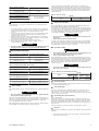
PRODUCT INFORMATION GRAPHICS
(Dwg. MHP0920)
(Dwg. MHP2686)
Air Out
Regulator
Lubricator
Air In
Filter
A
B
C
D
E
(Dwg. MHP0191)
Lift Slider
Handle
UP to Unlock
Exhaust Port
1-1/2 NPT
Air Inlet Port
1-1/4 NPT
Brake
Release
Port
1/4 NPT
Payout
Haul-In
A
C
B
D
E
F
(Dwg. MHP1809)
(Dwg. MHP2619)
(Dwg. MHP2688)
Form MHD56439 Edition 2
11

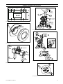
PRODUCT INFORMATION GRAPHICS (CONTINUED)
TOP
(Dwg. MHP2772)
(Dwg. MHP2398)
“Emergency
Stop” Button
“ON”
Button
Function
Levers
Pendant
Handle
A
B
C
D
(Dwg. MHP1892)
To Brake
Threaded
Ports
A
B
(Dwg. MHP2043)
M
J
A
C
B
D
K
G
H
L
F
E
(Dwg. MHP1176)
Position)
Regulator
Pressure
Gauge
C
D
Auxiliary Valve
(shown in Normal
Position)
Control
Valve
B
A
(Dwg. MHP1865)
12
Form MHD56439 Edition 2

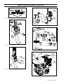
PRODUCT INFORMATION GRAPHICS (CONTINUED)
(Dwg. MHP1348)
A
B
C
E
D
Fill Plug
Position
Drum
Reduction Gear
Assembly
Level Plug
Position
Inboard
Upright
(Dwg. MHP0140)
D
C
B
Vent Cap
Drain Plug
Level Plug
A
Fill Cap
(Dwg. MHP2126)
Form MHD56439 Edition 2
13

DECLARATION OF CONFORMITY
(CS) PROHLÁŠENÍ O SHODĚ (DA) OVERENSSTEMMELSESERKLÆRING (DE) KONFORMITÄTSERKLÄRUNG (EL) ∆ΗΛΩΣΗ ΑΝΑΓΝΩΡΙΣΗΣ (ES) DECLARACIÓN
DE CONFORMIDAD (FI) VAKUUTUS NORMIEN TÄYTTÄMISESTÄ (FR) CERTIFICAT DE CONFORMITÉ (HU) MEGFELELŐSÉGI NYILATKOZAT (IT)
DICHIARAZIONE DI CONFORMITÀ (LT) ATBILSTĪBAS DEKLARĀCIJA (LV) ATITIKTIES DEKLARACIJA (NL) SCHRIFTELIJKE VERKLARING VAN
CONFORMITEIT (NO) KONFORMITETSERKLÆRING (PT) DECLARAÇÃO DE CONFORMIDADE (PL) DEKLARACJA ZGODNOŚCI (SK) PREHLÁSENIE O
ZHODE (SL) IZJAVA O SKLADNOSTI (SV) FÖRSÄKRAN OM ÖVERENSSTÄMMELSE
Ingersoll Rand 529, Avenue Roger Salengro, 59450 Sin Le Noble, France
Declare under our sole responsibility that the product: Pneumatic Winches
(CS) Prohlašujeme na svou zodpovědnost, že produkt: Pneumatický kladkostroj (DA) Erklærer som eneansvarlig, at nedenstående produkt: Pneumatisk lift
(DE) Erklären hiermit, gemäß unserer alleinigen Verantwortung, daß die Geräte: Druckluft-Kettenzugn (EL) Δηλώνουμε ότι με δική μας ευθύνη το προϊόν:
Πνευματικός ανυψωτήρας (ES) Declaramos que, bajo nuestra responsabilidad exclusiva, el producto: Polipasto neumático (FI) Vakuutamme ja kannamme yksin
täyden vastuun siitä, että tuote: Paineilmanostin (FR) Déclarons sous notre seule responsabilité que le produit: Palans pneumatiques (HU) Kizárólagos
felelősségünk tudatában kijelentjük, hogy a termék: Pneumatikus emelő (IT) Dichiariamo sotto la nostra unica responsabilità che il prodotto: Paranco
pneumatico (LT) Prisiimdami visà atsakomybæ pareiðkiame, kad gaminys: Pneimatiskās vinčas (LV) Deklarejam tikai uz musu atbildibu, ka šis ražojums:
Pneumatiniai suktuvai (NL) Verklaren, onder onze uitsluitende aansprakelijkheid, dat het produkt: Pneumatische takel (NO) Erklærer på ære og samvittighet at
produktet: Pneumatisk talje (PT) Declaramos sob a nossa exclusiva responsabilidade que o produto: Guinchos Pneumáticos (PL) Przyjmując pełną
odpowiedzialność, oświadczamy, że produkt: Wciągnik pneumatyczny (SK) Záväzne prehlasujeme, že výrobok: pneumatický kladkostroj (SL) Pod polno
odgovornostjo izjavljamo, da je izdelek: Pnevmatsko dvigalo (SV) Intygar enligt vårt ansvar att produkten: Tryckluftsdrivna lyftdon
Model: FA10i-( )-CE / Serial Number Range: A012535 and up
(CS) Model: / Rozsah výrobních čísel: (DA) Model: / Serienummerområde: (DE) Modell: / Seriennummernbereich: (EL) Μοντέλο: / Κλίμακα σειριακών αριθμών:
(ES) Modelo: / Números de serie: (FI) Malli: / Sarjanumeroalue: (FR) Modèle: / Gamme de numéros de série: (HU) Modell: / Gyártási szám-tartomány: (IT)
Modello: / Gamma delle matricole: (LT) Modelis: / Serijos numeriø eilë: (LV) Modelis: / Sçrijas numuru diapazons: (NL) Model: / Serienummer: (NO) Modell: /
Serienr: (PT) Modelo: / Gama de Nos de Série: (PL) Model: / Zakres numerów serii: (SK) Model: / Rozsah výrobných čísiel: (SL) Model: / Območje serijskih
številk: (SV) Modell: / Serienummer, mellan:
To which this declaration relates, is in compliance with provisions of Directive(s): 2006/42/EC (machinery), 94/9/EC (ATEX)
(CS) Ke kterým se toto prohlášení vztahuje, odpovídají ustanovením směrnic: (DA) som denne erklæring vedrører, overholder bestemmelserne i følgende
direktiv(er): (DE) auf das sich diese Erklärung bezieht, der folgenden Richtlinie entspricht: (EL) στο οποίο αναφέρεται αυτή η δήλωση, πληροί τις διατάξεις της
Οδηγίας: (ES) a los que se refiere la presente declaración, cumplen con todo lo establecido en las directivas: (FI) johon tämä vakuutus viittaa, täyttää
direktiiveissä: (FR) Objet de ce certificat, est conforme aux prescriptions des Directives: (HU) Amelyekre ezen nyilatkozat vonatkozik, megfelelnek a következő
irányelvek előírásainak: (IT) a cui si riferisce la presente dichiarazione è conforme alle normative delle direttive: (LT) Uz kuru šī deklarācija attiecas, atbilst
direktīvas(u) nosacījumiem: (LV) Kuriems taikoma ši deklaracija, atitinka šios direktyvos (-ų) nuostatas: (NL) waarop deze verklaring betrekking heeft overeenkomt
met de bepalingen van directieven: (NO) som denne erklæringen gjelder for, oppfyller bestemmelsene i direktivene: (PT) Ao qual se refere a presente declaração,
está de acordo com as provisões da(s) Directiva(s): (PL) Którego dotyczy niniejsza deklaracja, jest zgodny z wymogami dyrektyw: (SK) Na ktorý sa toto prehlásenie
vzt’ahuje, je v súlade s ustanoveniami Smernice (Smerníc): (SL) Na katerega se ta izjava o skladnosti nanaša, v skladu z določili smernic. (SV) Som detta intyg
avser, överensstämmer med följande direktiv:
By using the following Principle Standards: EN 292-1; EN 292-2; EN418; EN983; F.E.M.1.001; F.E.M.9.511; EN 13463-1; pr EN 13463-5; EN 1127-1
(CS) Použitím následujících zákonných norem: (DA) ved at være i overensstemmelse med følgende hovedstandard(er): (DE) Unter Anlehnung an die folgenden
Grundnormen entsprechen: (EL) Χρησιμοποιώντας ια παρακάτω κύρια πρότυπα: (ES) conforme a los siguientes estándares: (FI) esitetyt vaatimukset seuraavia
perusnormeja käytettäessä: (FR) En observant les normes de principe suivantes: (HU) A következő elvi szabványok alkalmazása mellett: (IT) Seguendo i principi
standard indicati di seguito: (LT) Izmantojot šādus galvenos standartus: (LV) Remiantis šiais pagrindiniais standartais: (NL) overeenkomstig de volgende
hoofdstandaards: (NO) Ved å bruke følgende prinsipielle standarder: (PT) observando as seguintes Normas Principais: (PL) Spełniając wymogi nastźpujących
głównych norm: (SK) Pri dodržaní nasledovných noriem: (SL) Uporabljeni osnovni standardi: (SV) Genom att använda följande principstandard:
Date: September, 2007
(CS) Datum: Září, 2007 (DA) Dato: September, 2007 (DE) Datum: September,2007 (EL) Ηµεροµηνία: Σεπτέμβριος, 2007 (ES) Fecha: Septiembre, 2007 (FI)
Päiväys: Heinäkuu, 2007 (FR) Date: Septembre, 2007 (HU) Dátum: 2007 július (IT) Data: Settembre, 2007 (LT) Datums: Septembris 2007 (LV) Datums:
Rugsėjis 2007 (NO) Dato: September, 2007 (NL) Datum: September, 2007 (SV) Datum: September, 2007 (PT) Data: Setembro, 2007 (PL) Data: Wrzesień 2007
(SK) Dátum: September 2007 (SL) Datum: September 2007.
Approved By:
(CS) Schválil: (DA) Godkendt af: (DE) Genehmigt von: (EL) Eγκρίθηκε από: (ES) Aprobado por: (FI) Hyväksytty: (FR) Approuvé par: (HU) Jóváhagyta: (IT)
Approvato da: (LT) Apstiprināja: (LV) Patvirtinta: (NL) Goedgekeurd door: (NO) Godkjent av: (PT) Aprovado por: (PL) Zatwierdzone przez: (SK) Schválil:
(SL) Odobril: (SV) Godkänt av:
Aaron Williamson- IREP - Seattle, WA USA
Engineering Product Manager
14 Form MHD56439 Edition 2

Form MHD56439 Edition 2 15

-
 1
1
-
 2
2
-
 3
3
-
 4
4
-
 5
5
-
 6
6
-
 7
7
-
 8
8
-
 9
9
-
 10
10
-
 11
11
-
 12
12
-
 13
13
-
 14
14
-
 15
15
-
 16
16


Ingersoll-Rand Force 5i Series Informazioni sul prodotto
- Tipo
- Informazioni sul prodotto
in altre lingue
Documenti correlati
-
Ingersoll-Rand FORCE 5i Man Rider FA150KGi Informazioni sul prodotto
-
-
Ingersoll-Rand LS1500RGC Istruzioni per l'uso
-
-
-
Altri documenti
-
Warn 87800 Guida d'installazione
-
-
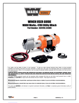 WARN Works 4700 Manuale utente
-
-
Regal 29 OBX Manuale del proprietario
-
Vetus RC12 Manuale utente
-
-
-
-
WEG Electric motors for explosive atmospheres Manuale utente
