DTS 03.MS014.EBLFP Manuale utente
- Categoria
- Proiettori
- Tipo
- Manuale utente
Questo manuale è adatto anche per

User’s Manual rel 1.3 GB

2
Le informazioni contenute in questo documento sono state attentamente redatte e
controllate. Tuttavia non è assunta alcuna responsabilità per eventuali inesattezze.
Tutti i diritti sono riservati e questo documento non può essere copiato, fotocopiato,
riprodotto per intero o in parte senza previo consenso scritto della D.T.S .
D.T.S. si riserva il diritto di apportare senza preavviso cambiamenti e modifiche
estetiche , funzionali o di design a ciascun proprio prodotto. D.T.S non assume alcuna
responsabilità sull’uso o sull’applicazione dei prodotti o dei circuiti descritti.
The information contained in this publication has been carefully prepared and
checked. However, no responsibility will be taken for any errors. All rights are
reserved and this document cannot be copied, photocopied or reproduced, in part or
completely, without prior written consent from D.T.S.
D.T.S. reserves the right to make any aesthetic, functional or design modifications to
any of its products without prior notice. D.T.S. assumes no responsibility for the use or
application of the products or circuits described herein.
Les informations contenues dans le présent manuel ont été rédigées et contrôlées
avec le plus grand soin. Nous déclinons toutefois toute responsabilité en cas
d'éventuelles inexactitudes. Tous droits réservés. Ce document ne peut être copié,
photocopié ou reproduit, dans sa totalité ou partiellement, sans le consentement
préalable de D.T.S.
D.T.S. se réserve le droit d'apporter toutes modifications et améliorations esthétiques,
fonctionnelles ou de design, sans préavis, à chacun de ses produits. D.T.S. décline
toute responsabilité sur l'utilisation ou sur l'application des produits ou des circuits
décrits.
Las informaciones contenidas en este documento han sido cuidadosamente
redactadas y controladas. Con todo, no se asume ninguna responsabilidad por
eventuales inexactitudes. Todos los derechos han sido reservados y este documento
no puede ser copiado, fotocopiado o reproducido, total o parcialmente, sin previa
autorización escrita de D.T.S.
D.T.S. se reserva el derecho a aportar sin previo aviso cambios y modificaciones de
carácter estético, funcional o de diseño a cada producto suyo. D.T.S. no se asume
responsabilidad de ningún tipo sobre la utilización o sobre la aplicación de los
productos o de los circuitos descritos.

3
INDEX:
1 - SYMBOLS ................................................................................................................ 4
2 - GENERAL WARNING ............................................................................................. 5
3 - GENERAL WARRANTY CONDITIONS ................................................................... 5
4 - TECHNICAL FEATURES ........................................................................................ 6
5 - ACCESSORIES ....................................................................................................... 8
6 - IMPORTANT SAFETY INFORMATION ................................................................... 9
6.1 Fire prevention...................................................................................................... 9
6.2 Prevention of electric shock .................................................................................. 9
6.3 Protection against ultraviolet radiation .................................................................. 9
6.4 Safety ................................................................................................................. 10
6.5 Level of protection against the penetration of solid and liquid objects ................ 10
6.6 Waste Electrical and Electronic Equipment (WEEE) directive ............................ 10
6.7 Long-life auto-charging buffer battery ................................................................. 10
7 - MOUNTING / REPLACING THE LAMP ................................................................. 11
8 - VOLTAGE AND FREQUENCY .............................................................................. 15
9 - INSTALLATION ..................................................................................................... 15
9.1 Safety cable ........................................................................................................ 17
9.2 Protection against liquids .................................................................................... 17
9.3 Movement ........................................................................................................... 18
9.4 Risk of fire .......................................................................................................... 18
9.5 Forced ventilation ............................................................................................... 18
9.6 Ambient temperature .......................................................................................... 18
10 - MAINS CONNECTION ......................................................................................... 19
10.1 Protection ......................................................................................................... 19
11 - DMX SIGNAL CONNECTION .............................................................................. 20
11.1 DMX addresses ................................................................................................ 21
11.2 Selecting the DMX address .............................................................................. 21
12 - FIRMWARE UPDATING ...................................................................................... 21
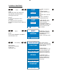
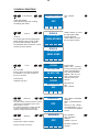
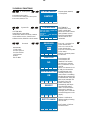
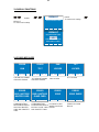
13 - DISPLAY FUNCTIONS ........................................................................................ 22
14 - ERROR MESSAGES ........................................................................................... 27
15 - OPENING THE PROJECTOR HOUSING ............................................................ 29
16 - REMOVING / REPLACING THE GOBOS ........................................................... 30
17 - PERIODIC CLEANING ........................................................................................ 31
17.1 Lenses and reflectors ....................................................................................... 31
17.2 Fans and air passages ..................................................................................... 31
18 - PERIODIC CONTROLS ....................................................................................... 31
19 - DMX PROTOCOL ................................................................................................ 32
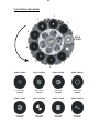
20 - ROTATING GOBO WHEEL ................................................................................. 45
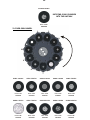
21 - FIXED GOBO WHEEL ......................................................................................... 46
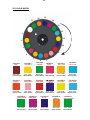
22 - COLOUR WHEEL ................................................................................................ 47

4
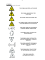
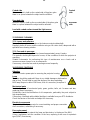
1- SYMBOLS
Graphic symbols used on this manual:
THIS SYMBOL INDICATES A HOT SURFACE
THIS SYMBOL INDICATES ELECTRIC
SHOCK RISK
THIS SYMBOL INDICATES GENERAL RISK
THIS SYMBOL MEANS “RADIATION FROM LAMP
CAN CAUSE DAMAGE TO EYES AND SKIN”
THIS SYMBOL INDICATES THE MAXIMUM
OPERATING AMBIENT TEMPERATURE
THIS SYMBOL MEANS “SUITABLE FOR
INDOOR USE ONLY”
THIS SYMBOL MEANS “SUITABLE FOR
MOUNTING ON NORMALLY FLAMMABLE
SURFACES”
THIS SYMBOL INDICATES THE MINIMUM
DISTANCE FROM THE ILLUMINATED
OBJECTS
THIS SYMBOL MEANS “DO NOT STARE
AT THE OPERATING LIGHT SOURCE”
THIS SYMBOL INDICATES
PHOTOBIOLOGICAL SAFETY
!
UV

5
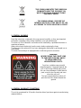
THIS SYMBOL INDICATES THE EUROPEAN
COMMUNITY DIRECTIVE 2012/19/EC ON
WASTE ELECTRICAL AND ELECTRONIC
EQUIPMENT (WEEE)
THIS SYMBOL MEANS “DISPOSE THE
INTERNAL BATTERY AT THE END OF ITS LIFE
ACCORDING TO THE REGULATION IN FORCE”
2- GENERAL WARNING
Read the instruction contained in this user manual carefully, as they give important
information regarding safety during installation, use and maintenance.
The device is not for domestic use and must be installed by a qualified electrician or
experienced person.
Always disconnect the device from the mains before replacing the lamp.
The lamp must be replaced if it has been damaged or deformed by prolonged use or
overheating.
The device must always be equipped with an efficient ground connection.
3- GENERAL WARRANTY CONDITIONS
The unit is guaranteed for 36 months from the date of purchase against manufacturing
material defects.
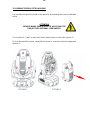
WARNING!
NEVER EXPOSE THE FRONT LENS
TO SUNLIGHT FROM ANY ANGLE
TO AVOID DAMAGE OF
HEAD INTERNAL PARTS.
Front lens could become powerful
magnifying glass if exposed towards the
sun or any strong artificial light source;
this can cause damage of head internal
parts, even for few seconds and even
when the unit is off.
The last command before switch off:
point the front lens down towards the
ground.

6
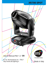
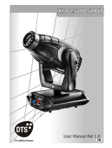
4- TECHNICAL FEATURES
DTS Product codes:
03.MS014.EBLFP MAX FPR Black finishing
Lamp
Philips MSD PLATINUM 16R 330W (16.000 Lumens)
Color temperature: 8000K
Remote lamp On-Off
Average lamp life: 1.500 hours
Optical group
Improved optical group made with 11 coated lenses
100.000 Lux at 5 m
16-bit motorized wide-excursion linear zoom
Beam opening:
2° - 37° (Beam-Spot mode)
10° - 60° (Wash projection)
16-bit motorized linear focus
Motorized Iris
Linear dimmer / shutter / strobe (0,85 flash/sec to 10 flash/sec)
Frost filter
Colour generation
Linear CMY + CTO
Color wheel (17 colors) with linear selection for perfect 2-color beams
Dynamic effects
Overlapping wheels for multiple effects:
Customizable rotating gobo wheel (8 gobos + Open Studio)
Customizable fixed gobo wheel (10 gobos)
Animation Wheel
4-facet rotating prism
Interface / Control / Programming
Li-Fe backup battery for controlling the main parameters even when MAX is not
powered
LCD graphic display + 4 soft-keys (control / management / monitoring of the main
parameters)
Controlled via DMX 512 and RDM standard digital communication protocols
Internal operating system updatable via DTS Dongle Firmware Uploader
DMX
33 DMX channels (Default) or 24 DMX channels

7
Pan & Tilt
'FPR' system (DTS patent)
Pan: limitless rotation, in both directions; 360° rotation in 1,56 sec.; Tilt: 270° (1,5 sec.)
Tri-phase stepper motor technology for ultra-fast silent movements
16-bit resolution
Selectable speed ranges
Pan / Tilt lock
Power supply
Electronic full-range 100-240Vac 50-60 Hz
Power consumption: 450W with PFC
Energy saving
Power saving mode (the lamp dims to 80% after shutter closure)
Connections
DMX: XLR 3-pole In/Out and 5-pole In/Out) panel connectors
Power supply: PowerCON In/Out panel connectors
Internal safety devices
Overvoltage circuit protection and overtemperature circuit protection
Operating ambient temperature
-10° / 40°
Weight
20 Kg
International certifications
2014/35/UE ; 2014/30/UE
IEC 62471 ; IEC 695-2-1
EN 60598-1 ; EN 62471 ; EN 61347-2-13
EN 60598-2-17 ; EN 55015 EMC ; EN 61347-1

8
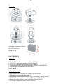
Dimensions
Packaging Dimensions (LxWxH)
610 x 510 x 520 mm
Weight: 25 Kg
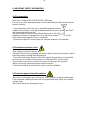
5- ACCESSORIES
As standard
1 x PowerCON female cable connector (Code 0520P014)
1 x XLR 5 Pins male cable connector (Code 0508B148)
1 x XLR 5 Pins female cable connector (Code 0508B147)
2 x Omega bracket with “Fast Lock” connection 1/4 turn (Code 02K00549)
1 x Rotating gobo assembled (Code 02SK0264)
User’s manual
Optional (on request)
• Lamp Philips MSD PLATINUM 16R 330W (Code 0505S036)
• Flightcase for 2 units (Code 0521C060.1)
• Aliscaf clamp for tube diameter 50 mm - max. load 100Kg (Code 0521A008)
• G-QUICK clamp Professional - max. load 100 Kg (Code 0521A037)
• Safety cable (3mm x 60 cm) - max. load 60Kg (Code 0521A010)
• DTS Dongle Firmware Uploader (Code 03.LA.206)

9
6- IMPORTANT SAFETY INFORMATION
6.1 Fire prevention:
MAX uses a Philips MSD PLATINUM 16R 330W lamp.
The use of any other alternative lamp is not recommended and will null and void the
fixture's warranty.
- It is permissible to place the unit on normally flammable surfaces.
Suitable for mounting on normally flammable materials surfaces greater than 200°C
with some combustion time lag.
-Minimum distance from the closest illuminable surface: 0,5 m.
-Replace any blown or damaged fuses only with those of identical value (6,3AT).
Refer to the wiring diagram if there is any doubt.
-Connect the projector to mains power via a thermal magnetic circuit breaker.
6.2 Prevention of electric shock:
-High voltage is present inside the unit.
Unplug the unit prior to performing any function which involves touching the inside of
the moving head, including lamp replacement.
-The level of technology inherent in the MAX requires the assistance of specialised
personnel for all servicing. Please refer to an authorised DTS service centre.
-A good earth connection is essential for proper functioning of the projector.
-Never connect the unit without proper earth connection.
-The fixture should be located in places with a good air ventilation.
6.3 Protection against ultraviolet radiation:
-Never turn on the lamp if any of the lenses, filters or plastic covering are damaged.
Their respective shielding functions will only operate efficiently if they are in perfect
working order.
-Never look directly the lamp when it is on.
UV

10
6.4 Safety:
-Risk Group 2 product according to EN 62471.
CAUTION. Do not look directly into the light output and do not view the light beam with
optical instruments or any device that may concentrate the beam.
May be harmful to the eyes and skin.
-Do not stare at the operating light source.
-The unit is not for household use and must be installed by a qualified electrician or
experienced person.
-The projector should always be installed with bolts, clamps and other tools that are
capable of supporting the weight of the unit.
-Always use a second safety cable to sustain the weight of the unit in case of the
failure of the main fixing point.
-The external surface of the unit, at various points, may exceed 70°C. Never handle
the unit until at least 20 minutes have elapsed since the lamp was turned off.
-Always replace the lamp if any physical damage is evident.
-Never install the fixture in an enclosed area lacking sufficient air flow.
The ambient temperature should not exceed 40°C.
-A hot lamp may explode, so always wait for at least 20 minutes prior to attempting to
replace the lamp.
-Always wear suitable hand protection when handling the lamp.
6.5 Level of protection against the penetration of solid and liquid objects:
-The projector is classified as an ordinary appliance and its protection level against the
penetration of solid and liquid objects is IP20.
Suitable for indoor use only.
6.6 Waste Electrical and Electronic Equipment (WEEE) directive:
- The projector, accessories and packaging should be sorted for environmental-friendly
recycling.
For EC countries: according to the European Directive 2012/19/EC for Waste
Electrical and Electronic Equipment and its implementation into national right,
luminaires that are no longer usable must be collected separately and disposed of in
an environmentally correct manner.
6.7 Long-life auto-charging buffer battery:
-The projector contains a rechargeable lead-acid or lithium iron tetraphosphate battery.
To preserve the environment, please dispose the battery at the end of its life according
to the regulation in force.
!
!

11
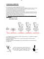
7- MOUNTING / REPLACING THE LAMP
WARNING
Turn off the lamp before opening the unit head covers.
Never look directly at the lamp when it’s lit.
Discharge lamps emits UV rays; radiation from this lamp
can cause damage to eyes and skin.
Let the projector cool for at least 20 minutes.
Switch off the unit and unplug the Mains AC cable connector
before replacing the lamp.
REPLACEMENT LAMP (Code 0505S036) :
Philips MSD PLATINUM 16R
Power 330W
Luminous flux 16.000 lm
Colour temperature 8.000K
Rated life 1500 hours
The use of any other alternative lamp is not recommended and will null and void the
fixture's warranty.
!
UV

12
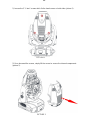
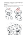
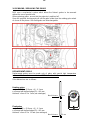
1) Loosen the 3 “¼ turn” screws which fix the head covers on both sides (picture 1) .
PICTURE 1
2) Once loosened the screws, simply lift the covers to access the internal components
(picture 2).
PICTURE 2

13
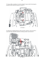
3) Using a phillips screwdriver, loose the indicated 2 screws which fix the lamp fan
assembly on both sides and remove it (picture 3);
PICTURE 3
4) Unplug the two indicated fast-on cable connectors (picture 4), then loose the 4
screws from the metal plates that fix the old lamp (picture 5) and remove it.
PICTURE 4

14
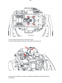
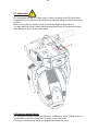
PICTURE 5
5) Put in place the new lamp in the lamp support.
Place the lamp terminals on the fan air conveyor side (Picture 6).
PICTURE 6
6) Lamp sub-assembly can now be re-installed, following backward all the above
listed steps.

15
8- VOLTAGE AND FREQUENCY
MAX operates at 100-240Vac 50-60 Hz.
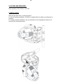
9- INSTALLATION
MAX may be either floor or ceiling mounted.
For floor mounting installations, the MAX is supplied with four rubber mounting feet on
the base.
For ceiling mounted installations, we reccomend the use of appropriate clamps to fix
the unit to the mounting surface.

16
The supporting structure from which the unit is hung should be capable of bearing the
weight of the unit, as should any clamps used to hang it.
The structure should also be sufficiently rigid so as not to move or shake whilst the
MAX is moving.
Four 1/4 turn Fast Locks connections placed in the base of the unit allow to hang the
MAX by using the two omega clamps (provided in the box) in conjunction with fixing
clamps for truss (fixing clamps are not included into the unit box).

17
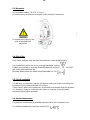
9.1- Safety cable
We recommend the use of a safety cable or chain connected to the MAX and to the
suspension truss in order to avoid the fixture accidentally falling should the main fixing
point fail.
Make sure that the iron cable or chain can bear the weight of the entire unit.
You may attach the safety chain/cord to the attachment point (A) located on the base
of the fixture, as shown in the picture below.
9.2 Protection against liquids
The projector contains electric and electronic components which should under no
circumstances come into contact with oil, water or any other liquid.
The proper unit functioning would be compromised should this occur.
!

18
9.3- Movement
Pan: unlimited rotation; Tilt: 270° (1,5 sec.).
Do not place any obstructions in the path of the projector's movement.
WARNING
Do not place any object in the
path of the projector’s
movement
9.4- Risk of fire
Each fixture produces heat and must be installed in a well-ventilated place.
It is permissible to place the unit on normally flammable surfaces.
Suitable for mounting on normally flammable materials surfaces greater than 200°C
with some combustion time lag.
Minimum distance from the object being illuminated is 0,5 m.
9.5- Forced ventilation
You will note, on inspection, that the unit features various air inlets and cooling fans
located on both the base and head of the fixture.
These should, under no circumstances, be blocked or obstructed whilst the projector
is in operation. Doing so could cause the fixture to seriously overheat thereby
compromising its proper operation.
9.6- Ambient temperature
The projector should never be installed in places that lack a constant air flow.
The ambient temperature should not exceed 40°C.
!

19
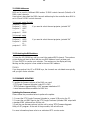
10- MAINS CONNECTION
MAX operates at 100-240Vac 50-60 Hz.
Prior to connecting the unit to your mains supply, ensure that the model in your
possession correctly matches the mains supply available.
For connection purposes, ensure that your plug is capable of supporting 2,5 amps
at 230 Vac, or 6 amps at 90 Vac each unit connected.
Strict adherence to regulatory norms is strongly recommended.
MAINS OUTPUT 100-240Vac 50-60 Hz (16A Max)
max 6 MAX units @ 230Vac
max 3 MAX units @ 90Vac
MAINS INPUT 100-240Vac 50-60 Hz
FUSE 6,3A T
10.1- Protection
The use of a thermal magnetic circuit breaker is recommended for each MAX.
A good earth connection is essential for the correct operation of the projector.
!

20
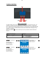
11- DMX SIGNAL CONNECTION
The unit operates using the digital DMX 512 signal.
Connection between the mixer and the projector or between projectors must be carried
out using a two pair screened ø 0.5 mm cable and a XLR 5 or 3 pins connector.
Ensure that the conductors do not touch each other.
Do not connect the cable ground to the XLR chassy.
The plug housing must be isolated. Connect the mixer signal to the DMX IN projector
plug and connect it to the next projector by connecting the DMX OUT plug on the first
projector to the DMX IN plug of the second one.
This way, all the projectors are cascade connected.
NB. If the display showing the DMX address flashes, then one of the following errors
has occurred:
- DMX signal not present
- DMX address not valid
- DMX reception problem
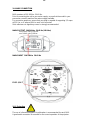
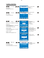
For Installations where long distance DMX cable connections are needed, we suggest
to use a DMX terminator.
The DMX terminator is a male XLR 3-5 pins connector with a 120 ohm resistor
between pin 2 and 3.
The DMX terminator must be plugged into the last unit (DMX out panel connector) of
the DMX line.
PLACE A 120 OHM RESISTOR BETWEEN PIN 2
AND 3 OF A MALE XRL CONNECTOR AND PLUG IT
INTO THE DMX OUT PANEL CONNECTOR OF THE
LAST UNIT CONNECTED TO THE DMX LINE
1
2
3
5
4
OUT
120 ohm
PIN 3
PIN 2
La pagina sta caricando ...
La pagina sta caricando ...
La pagina sta caricando ...
La pagina sta caricando ...
La pagina sta caricando ...
La pagina sta caricando ...
La pagina sta caricando ...
La pagina sta caricando ...
La pagina sta caricando ...
La pagina sta caricando ...
La pagina sta caricando ...
La pagina sta caricando ...
La pagina sta caricando ...
La pagina sta caricando ...
La pagina sta caricando ...
La pagina sta caricando ...
La pagina sta caricando ...
La pagina sta caricando ...
La pagina sta caricando ...
La pagina sta caricando ...
La pagina sta caricando ...
La pagina sta caricando ...
La pagina sta caricando ...
La pagina sta caricando ...
La pagina sta caricando ...
La pagina sta caricando ...
La pagina sta caricando ...
La pagina sta caricando ...
-
 1
1
-
 2
2
-
 3
3
-
 4
4
-
 5
5
-
 6
6
-
 7
7
-
 8
8
-
 9
9
-
 10
10
-
 11
11
-
 12
12
-
 13
13
-
 14
14
-
 15
15
-
 16
16
-
 17
17
-
 18
18
-
 19
19
-
 20
20
-
 21
21
-
 22
22
-
 23
23
-
 24
24
-
 25
25
-
 26
26
-
 27
27
-
 28
28
-
 29
29
-
 30
30
-
 31
31
-
 32
32
-
 33
33
-
 34
34
-
 35
35
-
 36
36
-
 37
37
-
 38
38
-
 39
39
-
 40
40
-
 41
41
-
 42
42
-
 43
43
-
 44
44
-
 45
45
-
 46
46
-
 47
47
-
 48
48


DTS 03.MS014.EBLFP Manuale utente
- Categoria
- Proiettori
- Tipo
- Manuale utente
- Questo manuale è adatto anche per
in altre lingue
- English: DTS 03.MS014.EBLFP User manual