
—
RELION® PROTECTION AND CONTROL
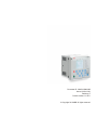
615 series ANSI
Engineering Manual


Document ID: 1MAC108982-MB
Issued: 2018-02-26
Revision: E
Product version: 5.0 FP1
© Copyright 2018 ABB. All rights reserved

Copyright
This document and parts thereof must not be reproduced or copied without written
permission from ABB, and the contents thereof must not be imparted to a third party, nor
used for any unauthorized purpose.
The software or hardware described in this document is furnished under a license and may
be used, copied, or disclosed only in accordance with the terms of such license.
Trademarks
ABB and Relion are registered trademarks of the ABB Group. All other brand or product
names mentioned in this document may be trademarks or registered trademarks of their
respective holders.
Warranty
Please inquire about the terms of warranty from your nearest ABB representative.
www.abb.com/mediumvoltage
www.abb.com/substationautomation

Disclaimer
The data, examples and diagrams in this manual are included solely for the concept or
product description and are not to be deemed as a statement of guaranteed properties. All
persons responsible for applying the equipment addressed in this manual must satisfy
themselves that each intended application is suitable and acceptable, including that any
applicable safety or other operational requirements are complied with. In particular, any
risks in applications where a system failure and/or product failure would create a risk for
harm to property or persons (including but not limited to personal injuries or death) shall
be the sole responsibility of the person or entity applying the equipment, and those so
responsible are hereby requested to ensure that all measures are taken to exclude or
mitigate such risks.
This product has been designed to be connected and communicate data and information
via a network interface which should be connected to a secure network. It is the sole
responsibility of the person or entity responsible for network administration to ensure a
secure connection to the network and to take the necessary measures (such as, but not
limited to, installation of firewalls, application of authentication measures, encryption of
data, installation of anti virus programs, etc.) to protect the product and the network, its
system and interface included, against any kind of security breaches, unauthorized access,
interference, intrusion, leakage and/or theft of data or information. ABB is not liable for
any such damages and/or losses.
This document has been carefully checked by ABB but deviations cannot be completely
ruled out. In case any errors are detected, the reader is kindly requested to notify the
manufacturer. Other than under explicit contractual commitments, in no event shall ABB
be responsible or liable for any loss or damage resulting from the use of this manual or the
application of the equipment.

Conformity
This product complies with the directive of the Council of the European Communities on
the approximation of the laws of the Member States relating to electromagnetic
compatibility (EMC Directive 2004/108/EC) and concerning electrical equipment for use
within specified voltage limits (Low-voltage directive 2006/95/EC). This conformity is
the result of tests conducted by ABB in accordance with the product standards EN 50263
and EN 60255-26 for the EMC directive, and with the product standards EN 60255-1 and
EN 60255-27 for the low voltage directive. The product is designed in accordance with the
international standards of the IEC 60255 series and ANSI C37.90. This product complies
with the UL 508 certification.

Safety information
Dangerous voltages can occur on the connectors, even though the
auxiliary voltage has been disconnected.
Non-observance can result in death, personal injury or substantial
property damage.
Only a competent electrician is allowed to carry out the electrical
installation.
National and local electrical safety regulations must always be followed.
The frame of the protection relay has to be carefully grounded.
When the plug-in unit has been detached from the case, do not touch the
inside of the case. The relay case internals may contain high voltage
potential and touching these may cause personal injury.
The protection relay contains components which are sensitive to
electrostatic discharge. Unnecessary touching of electronic components
must therefore be avoided.
Whenever changes are made in the protection relay, measures should be
taken to avoid inadvertent tripping.


Table of contents
Section 1 Introduction............................................................................5
This manual.............................................................................................. 5
Intended audience.................................................................................... 5
Product documentation.............................................................................6
Product documentation set..................................................................6
Document revision history................................................................... 6
Related documentation........................................................................7
Symbols and conventions.........................................................................7
Symbols...............................................................................................7
Document conventions........................................................................ 7
Functions, codes and symbols............................................................ 8
Section 2 Relay engineering process..................................................15
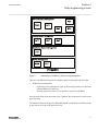
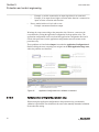
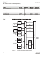
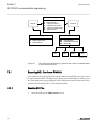
Monitoring and control system structure.................................................18
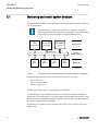
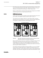
Standard configuration concept.............................................................. 19
Workflow................................................................................................. 21
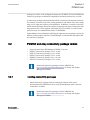
Section 3 PCM600 tool........................................................................25
Connectivity packages............................................................................26
PCM600 and relay connectivity package version................................... 27
Installing connectivity packages........................................................ 27
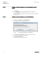
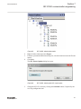
Installing connectivity packages by using the connectivity
package installer...........................................................................28
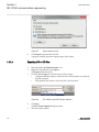
Installing connectivity packages by using Update Manager......... 28
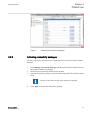
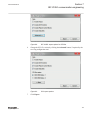
Activating connectivity packages.......................................................29
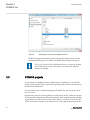
PCM600 projects.................................................................................... 30
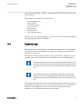
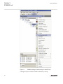
Technical key..........................................................................................31
IEC 61850 naming conventions to identify an IED............................ 32
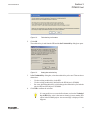
Setting the technical key....................................................................35
Communication between PCM600 and the protection relay...................38
Setting up IP addresses.................................................................... 39
IED Update............................................................................................. 39
Prerequisites for local and remote updates....................................... 40
Updating firmware or language......................................................... 40
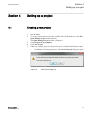
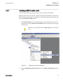
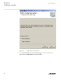
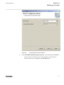
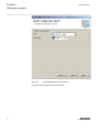
Section 4 Setting up a project............................................................. 45
Creating a new project............................................................................45
Table of contents
615 series ANSI 1
Engineering Manual

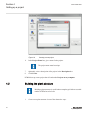
Building the plant structure..................................................................... 46
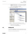
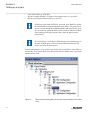
Inserting an IED...................................................................................... 47
Inserting an IED in online mode........................................................ 49
Inserting an IED in offline mode........................................................ 58
Inserting an IED from the template directory..................................... 60
Inserting an IED by importing a .pcmi file.......................................... 62
Setting the IED IP address in a project...................................................64
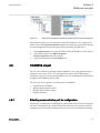
COM600S project................................................................................... 65
Selecting communication port for configuration.................................65
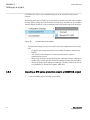
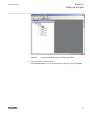
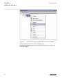
Importing a 615 series protection relay in a COM600S project......... 66
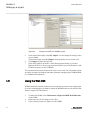
Using the Web HMI.................................................................................70
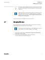
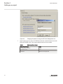
Managing IED users............................................................................... 71
PCM600 project's IEC 61850 version identification................................74
Section 5 Protection and control engineering......................................77
Application Configuration tool................................................................. 77
Function blocks..................................................................................78
Signals and signal management....................................................... 79
Function block execution parameters................................................80
Execution order and feedback loops................................................. 81
Configuration parameters.................................................................. 83
Connections and variables................................................................ 83
Hardware channels............................................................................84
Online monitoring.............................................................................. 84
Validation...........................................................................................85
Validation when creating an application configuration..................85
Validation on demand...................................................................85
Validation when writing to the protection relay............................. 86
Configuration load calculation........................................................... 87
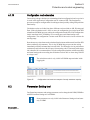
Parameter Setting tool............................................................................ 87
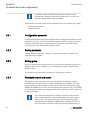
Configuration parameter....................................................................88
Setting parameter.............................................................................. 88
Setting group..................................................................................... 88
Parameter import and export.............................................................88
Parameter organization..................................................................... 89
Signal Matrix tool.................................................................................... 89
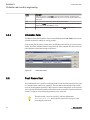
Load Profile tool......................................................................................92
Opening and closing Load Profile tool...............................................92
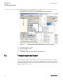
Load Profile tool user interface..........................................................95
Information fields............................................................................... 96
Table of contents
2 615 series ANSI
Engineering Manual

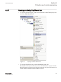
Fault Record tool.................................................................................... 96
Opening and closing Fault Record tool............................................. 97
Fault Record tool interface................................................................ 98
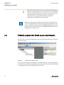
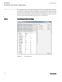
IED Compare.......................................................................................... 99
Starting IED Compare..................................................................... 100
IED Compare tool interface............................................................. 100
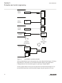
Protection and control blocking examples............................................ 102
Protection blocking example............................................................103
Control blocking example................................................................ 104
Section 6 LHMI engineering.............................................................. 105
Single-line diagram engineering........................................................... 105
Diagrams in Graphical Display Editor..............................................105
Display window and sequence order..........................................106
Symbol library.............................................................................107
Supported single-line diagram symbols......................................107
HMI display raster layout and text font selection........................ 109
Text handling.............................................................................. 109
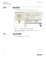
Adding static text........................................................................ 110
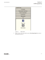
Adding select buttons................................................................. 110
Adding measurands....................................................................112
Adding a busbar......................................................................... 113
Adding symbols into a display page........................................... 114
Drawing lines to create links.......................................................115
Bay configuration engineering......................................................... 116
Linking process objects.............................................................. 117
Creating a complete HMI display page.......................................119
Template export and import..................................................................120
Exporting a template........................................................................121
Importing a template........................................................................121
HMI event filtering.................................................................................121
Starting HMI event filtering.............................................................. 122
Setting visibility of HMI events.........................................................122
Searching events.............................................................................123
Saving event filter configuration...................................................... 124
Section 7 IEC 61850 communication engineering............................ 125
IEC 61850 protocol references and pre-conditions.............................. 125
IEC 61850 interface.............................................................................. 125
IEC 61850 interface in the protection relay..................................... 132
GOOSE data exchange..............................................................133
Table of contents
615 series ANSI 3
Engineering Manual

Function view for IEC 61850 in PCM600.........................................134
Station configuration description file types...................................... 134
IEC 61850 engineering process........................................................... 135
Exporting SCL files from PCM600...................................................136
Exporting SCD files.................................................................... 136
Exporting ICD or CID files.......................................................... 138
Engineering vertical and horizontal communication........................ 140
Importing SCL files to PCM600....................................................... 141
Importing SCD files.....................................................................142
Importing ICD or CID files...........................................................145
Writing communication configuration to the IED..............................145
Section 8 Glossary............................................................................ 147
Table of contents
4 615 series ANSI
Engineering Manual

Section 1 Introduction
1.1 This manual
The engineering manual contains instructions on how to engineer the protection relays
using the different tools in PCM600. The manual provides instructions on how to set up
a PCM600 project and insert relays to the project structure. The manual also recommends
a sequence for engineering of protection and control functions, LHMI functions as well as
communication engineering for IEC 61850 and other supported protocols.
1.2 Intended audience
This manual addresses system and project engineers involved in the engineering process
of a project, and installation and commissioning personnel, who use technical data during
engineering, installation and commissioning, and in normal service.
The system engineer must have a thorough knowledge of the application, protection and
control equipment and the configured functional logic in the relays. The installation and
commissioning personnel must have a basic knowledge of handling electronic equipment.
1MAC108982-MB E Section 1
Introduction
615 series ANSI 5
Engineering Manual

1.3 Product documentation
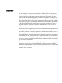
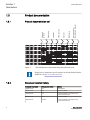
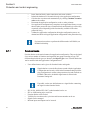
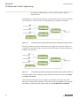
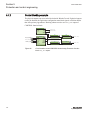
1.3.1 Product documentation set
Planning &
purchase
Engineering
Installation
Commissioning
Operation
Maintenance
Decommissioning,
deinstallation & disposal
Quick start guide
Quick installation guide
Brochure
Product guide
Operation manual
Installation manual
Connection diagram
Engineering manual
Technical manual
Application manual
Communication protocol manual
IEC 61850 engineering guide
Point list manual
Cyber security deployment guideline
GUID-12DC16B2-2DC1-48DF-8734-0C8B7116124C V2 EN
Figure 1: The intended use of documents during the product life cycle
Product series- and product-specific manuals can be downloaded from the
ABB Web site http://www.abb.com/relion.
1.3.2 Document revision history
Document revision/date
Product series version History
A/2011-04-15 4.0 First release
B/2011-06-16 4.0 Content updated
C/2015-04-29 4.2 Content updated to correspond to the
product series version
D/2015-05-29 4.2 Content updated
E/2018-02-26 5.0 FP1 Content updated to correspond to the
product series version
Section 1 1MAC108982-MB E
Introduction
6 615 series ANSI
Engineering Manual

Download the latest documents from the ABB Web site
http://www.abb.com/substationautomation.
1.3.3 Related documentation
Product series- and product-specific manuals can be downloaded from the ABB Web site
http://www.abb.com/substationautomation.
1.4 Symbols and conventions
1.4.1 Symbols
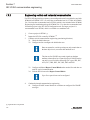
The caution icon indicates important information or warning related to the
concept discussed in the text. It might indicate the presence of a hazard
which could result in corruption of software or damage to equipment or
property.
The information icon alerts the reader of important facts and conditions.
The tip icon indicates advice on, for example, how to design your project
or how to use a certain function.
Although warning hazards are related to personal injury, it is necessary to understand that
under certain operational conditions, operation of damaged equipment may result in
degraded process performance leading to personal injury or death. Therefore, comply
fully with all warning and caution notices.
1.4.2 Document conventions
A particular convention may not be used in this manual.
• Abbreviations and acronyms are spelled out in the glossary. The glossary also
contains definitions of important terms.
• Push button navigation in the LHMI menu structure is presented by using the push
button icons.
1MAC108982-MB E Section 1
Introduction
615 series ANSI 7
Engineering Manual

To navigate between the options, use and .
• Menu paths are presented in bold.
Select Main menu/Settings.
• LHMI messages are shown in Courier font.
To save the changes in nonvolatile memory, select Yes and press .
• Parameter names are shown in italics.
The function can be enabled and disabled with the Operation setting.
• Parameter values are indicated with quotation marks.
The corresponding parameter values are "Enabled" and "Disabled".
• Input/output messages and monitored data names are shown in Courier font.
When the function picks up, the PICKUP output is set to TRUE.
• Dimensions are provided both in inches and mm. If it is not specifically mentioned,
the dimension is in mm.
• This document assumes that the parameter setting visibility is "Advanced".
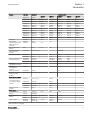
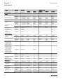
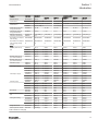
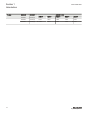
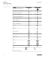
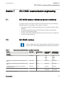
1.4.3 Functions, codes and symbols
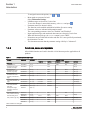
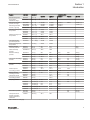
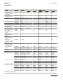
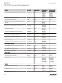
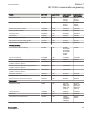
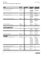
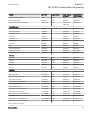
All available functions are listed in the table. All of them may not be applicable to all
products.
Table 1: Functions included in the relays
Function
IEC 61850 IEC 60617 ANSI/C37.2-2008
RED615 REF615 REG615 REM615 RET615
Protection
Three-phase non-
directional overcurrent
protection, low stage
PHLPTOC1 3I> (1) 51P-1 51P-1 51P 51P (1)
PHLPTOC2 3I> (2) 51P-2 51P (2)
Three-phase non-
directional overcurrent
protection, high stage
PHHPTOC1 3I>> (1) 50P-1 50P-1 50P-1 50P-1 (1)
PHHPTOC2 3I>> (2) 50P-2 50P-2 50P-1 (2)
Three-phase non-
directional overcurrent
protection, instantaneous
stage
PHIPTOC1 3I>>> (1) 50P-3 50P-3 50P-3 50P-3 50P-3 (1)
PHIPTOC2 3I>>> (2) 50P-3 (2)
Three-phase directional
overcurrent protection, low
stage
DPHLPDOC1 3I> -> (1) 67/51P-1 67/51P-1 67/51P-1 67/51P-1(2)
DPHLPDOC2 3I> -> (2) 67/51P-2 67/51P-2 67/51P-2(2)
Three-phase directional
overcurrent protection,
high stage
DPHHPDOC1 3I>> -> (1) 67/50P-1 67/50P-1 67/50P-1
DPHHPDOC2 3I>> -> (2) 67/50P-2
Three-phase voltage-
dependent overcurrent
protection
PHPVOC1 3I(U)> (1) 51V
Non-directional ground-
fault protection, low stage
EFLPTOC1 Io> (1) 51G 51G
EFLPTOC2 Io> (2) 51N-1 51N (2)
Non-directional ground-
fault protection, high stage
EFHPTOC1 Io>> (1) 50G-1 50G-1 50G-1 50G-1
EFHPTOC2 Io>> (2) 50G-2 50G-2 50G-2 (2)
EFHPTOC3 Io>> (3) 50N-1
EFHPTOC4 Io>> (4) 50N-2
Table continues on next page
Section 1 1MAC108982-MB E
Introduction
8 615 series ANSI
Engineering Manual

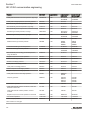
Function IEC 61850 IEC 60617 ANSI/C37.2-2008
RED615 REF615 REG615 REM615 RET615
Non-directional ground-
fault protection,
instantaneous stage
EFIPTOC1 Io>>> (1) 50G-3
EFIPTOC2 Io>>> (2) 50N-3
Directional ground-fault
protection, low stage
DEFLPDEF1 Io> -> (1) 67/51N-1 67/51N-1 67/51N-1 67/51N 67/51N-1 (2)
DEFLPDEF2 Io> -> (2) 67/51N-2 67/51N-2 67/51N-2 67/51N-2 (2)
Directional ground-fault
protection, high stage
DEFHPDEF1 Io>> -> (1) 67/50N-1 67/50N-1 67/50N-1
DEFHPDEF2 Io>> -> (2) 67/50N-2
Admittance-based ground-
fault protection
EFPADM1 Yo> -> (1) 21YN-1 21YN-1
EFPADM2 Yo> -> (2) 21YN-2 21YN-2
EFPADM3 Yo> -> (3) 21YN-3 21YN-3
Wattmetric-based ground-
fault protection
WPWDE1 Po> -> (1) 32N-1 32N-1
WPWDE2 Po> -> (2) 32N-2 32N-2
WPWDE3 Po> -> (3) 32N-3 32N-3
Transient/intermittent
ground-fault protection
INTRPTEF1 Io> -> IEF (1) 67NIEF 67NIEF
Harmonics-based ground-
fault protection
HAEFPTOC1 Io>HA (1) 51NHA 51NHA
Negative-sequence
overcurrent protection
NSPTOC1 I2> (1) 46-1 46-1 46 (1)
NSPTOC2 I2> (2) 46-2 46-2 46 (2)
Phase discontinuity
protection
PDNSPTOC1 I2/I1> (1) 46PD 46PD
Residual overvoltage
protection
ROVPTOV1 Uo> (1) 59G 59G 59G 59G-1 59G (1)
ROVPTOV2 Uo> (2) 59N-1 59N-1 59N-1 59N-1 59N (1)
ROVPTOV3 Uo> (3) 59N-2 59N-2 59N (2)
Three-phase undervoltage
protection
PHPTUV1 3U< (1) 27-1 27-1 27-1 27-1 27-1 (2)
PHPTUV2 3U< (2) 27-2 27-2 27-2 27-2 27-2 (2)
PHPTUV3 3U< (3) 27-3 27-3
Three-phase overvoltage
protection
PHPTOV1 3U> (1) 59-1 59-1 59-1 59-1 59-1 (2)
PHPTOV2 3U> (2) 59-2 59-2 59-2 59-2 59-2 (2)
PHPTOV3 3U> (3) 59-3 59-3
Positive-sequence
undervoltage protection
PSPTUV1 U1< (1) 47U-1 47U-1 47U-1 27PS
PSPTUV2 U1< (2) 47U-2 47U-2
Negative-sequence
overvoltage protection
NSPTOV1 U2> (1) 47-1 47-1 47-1 47-1
NSPTOV2 U2> (2) 47-2 47-2 47-2
Three-phase remnant
undervoltage protection
MSVPR1 3U< (1) 27R-1 27R
MSVPR2 3U< (2) 27R-2
Frequency protection FRPFRQ1 f>/f<,df/dt (1) 81-1 81-1 81-1 81-1 81-1 (2)
FRPFRQ2 f>/f<,df/dt (2) 81-2 81-2 81-2 81-2 81-2 (2)
FRPFRQ3 f>/f<,df/dt (3) 81-3 81-3 81-3
FRPFRQ4 f>/f<,df/dt (4) 81-4 81-4 81-4
FRPFRQ5 f>/f<,df/dt (5) 81-5 81-5
FRPFRQ6 f>/f<,df/dt (6) 81-6 81-6
Overexcitation protection OEPVPH1 U/f> (1) 24 24-1 24-1 (2)
OEPVPH2 U/f> (2) 24-2 24-2 (2)
Three-phase thermal
protection for feeders,
cables and distribution
transformers
T1PTTR1 3Ith>F (1) 49F-1 49F-1
Table continues on next page
1MAC108982-MB E Section 1
Introduction
615 series ANSI 9
Engineering Manual

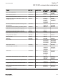
Function IEC 61850 IEC 60617 ANSI/C37.2-2008
RED615 REF615 REG615 REM615 RET615
Three-phase thermal
overload protection, two
time constants
T2PTTR1 3Ith>T/G/C (1) 49T-1 49T-1 49T (1)
Negative-sequence
overcurrent protection for
machines
MNSPTOC1 I2>M (1) 46M-1 46M-1
MNSPTOC2 I2>M (2) 46M-2 46M-2
Loss of load supervision LOFLPTUC1 3I< (1) 37M-1
LOFLPTUC2 3I< (2) 37M-2
Motor load jam protection JAMPTOC1 Ist> (1) 51LR-1
JAMPTOC2 Ist> (2) 51LR-2
Motor start-up supervision STTPMSU1 Is2t n< (1) 66/51LRS
Phase reversal protection PREVPTOC1 I2>> (1) 46R
Thermal overload
protection for motors
MPTTR1 3Ith>M (1) 49M
Binary signal transfer BSTGGIO1 BST (1) BST-1
Motor differential protection MPDIF1 3dl>M 87G-1 87M
High-impedance
differential protection for
phase A
HIAPDIF1 dHi_A>(1) 87A 87A
High-impedance
differential protection for
phase B
HIBPDIF1 dHi_B>(1) 87B 87B
High-impedance
differential protection for
phase C
HICPDIF1 dHi_C>(1) 87C 87C
Stabilized and
instantaneous differential
protection for two-winding
transformers
TR2PTDF1 3dI>T (1) 87T
Numerically stabilized low-
impedance restricted
ground-fault protection
LREFPNDF1 dIoLo> (1) 87LOZREF 87LOZREF (2)
Circuit breaker failure
protection
CCBRBRF1 3I>/Io>BF (1) 50BF-1 50BF-1 50BF-1 50BF 50BF (1)
CCBRBRF2 3I>/Io>BF (2) 50BF-2 50BF (2)
Three-phase inrush
detector
INRPHAR1 3I2f> (1) INR-1 INR-1 INR-1
Switch onto fault CBPSOF1 SOTF (1) SOTF-1 SOTF-1
Master trip TRPPTRC1 Master Trip (1) 86/94-1 86/94-1 86/94-1 86/94-1 86/94-1
TRPPTRC2 Master Trip (2) 86/94-2 86/94-2 86/94-2 86/94-2 86/94-2
TRPPTRC3 Master Trip (3) 86/94-3 86/94-3 86/94-3 86/94-3
TRPPTRC4 Master Trip (4) 86/94-4 86/94-4 86/94-4 86/94-4
TRPPTRC5 Master Trip (5) 86/94-5 86/94-5 86/94-5 86/94-5
TRPPTRC6 Master Trip (6) 86/94-6
Arc protection ARCSARC1 ARC (1) AFD-1 AFD-1 AFD-1 AFD-1 (2)
ARCSARC2 ARC (2) AFD-2 AFD-2 AFD-2 AFD-2 (2)
ARCSARC3 ARC (3) AFD-3 AFD-3 AFD-3 AFD-3 (2)
Multipurpose protection MAPGAPC1 MAP (1) MAP-1 MAP-1 MAP-1 MAP-1 MAP-1
MAPGAPC2 MAP (2) MAP-2 MAP-2 MAP-2 MAP-2 MAP-2
MAPGAPC3 MAP (3) MAP-3 MAP-3 MAP-3 MAP-3 MAP-3
MAPGAPC4 MAP (4) MAP-4 MAP-4 MAP-4 MAP-4 MAP-4
MAPGAPC5 MAP (5) MAP-5 MAP-5 MAP-5 MAP-5 MAP-5
MAPGAPC6 MAP (6) MAP-6 MAP-6 MAP-6 MAP-6 MAP-6
Table continues on next page
Section 1 1MAC108982-MB E
Introduction
10 615 series ANSI
Engineering Manual

Function IEC 61850 IEC 60617 ANSI/C37.2-2008
RED615 REF615 REG615 REM615 RET615
MAPGAPC7 MAP (7) MAP-7 MAP-7 MAP-7 MAP-7 MAP-7
MAPGAPC8 MAP (8) MAP-8 MAP-8 MAP-8 MAP-8 MAP-8
MAPGAPC9 MAP (9) MAP-9 MAP-9 MAP-9 MAP-9 MAP-9
MAPGAPC10 MAP (10) MAP-10 MAP-10 MAP-10 MAP-10 MAP-10
MAPGAPC11 MAP (11) MAP-11 MAP-11 MAP-11 MAP-11 MAP-11
MAPGAPC12 MAP (12) MAP-12 MAP-12 MAP-12 MAP-12 MAP-12
MAPGAPC13 MAP (13) MAP-13 MAP-13 MAP-13 MAP-13 MAP-13
MAPGAPC14 MAP (14) MAP-14 MAP-14 MAP-14 MAP-14 MAP-14
MAPGAPC15 MAP (15) MAP-15 MAP-15 MAP-15 MAP-15 MAP-15
MAPGAPC16 MAP (16) MAP-16 MAP-16 MAP-16 MAP-16 MAP-16
MAPGAPC17 MAP (17) MAP-17 MAP-17 MAP-17 MAP-17 MAP-17
MAPGAPC18 MAP (18) MAP-18 MAP-18 MAP-18 MAP-18 MAP-18
Fault locator SCEFRFLO1 FLOC (1) 21FL-1 21FL-1
Loss of phase PHPTUC1 3I< (1) 37-1
Line differential protection
with in-zone power
transformer
LNPLDF1 3Id/I> (1) 87L-1
High-impedance fault
detection
PHIZ1 HIF (1) HIZ-1 HIZ-1
Third harmonic-based
stator ground-fault
protection
H3EFPSEF1 dUo>/Uo3H (1) 27/59THN
Underpower protection DUPPDPR1 P< (1) 32U-1 32U-1 32U-1
DUPPDPR2 P< (2) 32U-2 32U-2 32U-2
Reverse power/directional
overpower protection
DOPPDPR1 P>/Q> (1) 32R/32O-1 32R-32 32O-1
DOPPDPR2 P>/Q> (2) 32R/32O-2 32R-32 32O-2
DOPPDPR3 P>/Q> (3) 32R-32 32O-3
Three-phase
underexcitation protection
UEXPDIS1 X< (1) 40-1
Three-phase
underimpedance
protection
UZPDIS1 Z<G (1) 21G-1
Out-of-step protection OOSRPSB1 OOS (1) 78-1
Multifrequency admittance-
based ground-fault
protection
MFADPSDE1 Io> ->Y (1) 67YN-1
Interconnection functions
Directional reactive power
undervoltage protection
DQPTUV1 Q> ->,3U< (1) 32Q-27
Low-voltage ride-through
protection
LVRTPTUV1 U<RT (1) 27RT-1
LVRTPTUV2 U<RT (2) 27RT-2
LVRTPTUV3 U<RT (3) 27RT-3
Voltage vector shift
protection
VVSPPAM1 VS (1) 78V-1
Power quality
Current total demand
distortion
CMHAI1 PQM3I (1) PQI-1 PQI-1 PQI-1
CMHAI2 PQM3I(B)
Voltage total harmonic
distortion
VMHAI1 PQM3U (1) PQVPH-1 PQVPH-1 PQVPH-1
VMHAI2 PQM3U(B) PQVPH-2
Voltage variation PHQVVR1 PQMU (1) PQSS-1 PQSS-1 PQSS-1
PHQVVR2 PQ 3U<>(B) PQSS-2
Table continues on next page
1MAC108982-MB E Section 1
Introduction
615 series ANSI 11
Engineering Manual

Function IEC 61850 IEC 60617 ANSI/C37.2-2008
RED615 REF615 REG615 REM615 RET615
Voltage unbalance VSQVUB1 PQUUB (1) PQVUB-1 PQVUB-1 PQVUB-1
Control
Circuit-breaker control CBXCBR1 I <-> O CB (1) 52-1 52-1 52-1 52 52 (1)
CBXCBR2 I <-> O CB (2) 52-2 52 (2)
Disconnector control DCXSWI1 I <-> O DCC (1) 29DS-1 29DS-1 29DS-1 29DS-1 29DS-1
DCXSWI2 I <-> O DCC (2) 29DS-2 29DS-2 29DS-2 29DS-2 29DS-2
Grounding switch control ESXSWI1 I <-> O ESC (1) 29GS-1 29GS-1 29GS-1 29GS-1 29GS-1
Disconnector position
indication
DCSXSWI1 I <-> O DC (1) 52-TOC 52-TOC 52-TOC 52-TOC 52-TOC
DCSXSWI2 I <-> O DC (2) 29DS-1 29DS-1 29DS-1 29DS-1 29DS-1
DCSXSWI3 I <-> O DC (3) 29DS-2 29DS-2 29DS-2 29DS-2 29DS-2
Grounding switch
indication
ESSXSWI1 I <-> O ES (1) 29GS-1 29GS-1 29GS-1 29GS-1 29GS-1
ESSXSWI2 I <-> O ES (2) 29GS-2 29GS-2 29GS-2 29GS-2 29GS-2
Emergency startup ESMGAPC1 ESTART (1) 62EST
Autoreclosing DARREC1 O -> I (1) 79 79
Tap changer position
indication
TPOSYLTC1 TPOSM (1) 84T
Synchronism and
energizing check
SECRSYN1 SYNC (1) 25 25 25 25 (2)
Condition monitoring
Circuit-breaker condition
monitoring
SSCBR1 CBCM (1) 52CM-1 52CM-1 52CM-1 52CM 52CM (1)
SSCBR2 CBCM (2) 52CM-2 52CM (2)
Trip circuit supervision TCSSCBR1 TCS (1) TCM-1 TCM-1 TCM-1 TCM-1 TCM-1
TCSSCBR2 TCS (2) TCM-2 TCM-2 TCM-2 TCM-2 TCM-2
Current circuit supervision CCSPVC1 MCS 3I (1) CCM CCM CCM
Current transformer
supervision for high-
impedance protection
scheme for phase A
HZCCASPVC1 MCS I_A(1) MCS-A
Current transformer
supervision for high-
impedance protection
scheme for phase B
HZCCBSPVC1 MCS I_B(1) MCS-B
Current transformer
supervision for high-
impedance protection
scheme for phase C
HZCCCSPVC1 MCS I_C(1) MCS-C
Fuse failure supervision SEQSPVC1 FUSEF (1) 60-1 60-1 60-1 60 60 (1)
SEQSPVC2 FUSEF (2) 60-2
Protection communication
supervision
PCSITPC1 PCS (1) PCS-1
Runtime counter for
machines and devices
MDSOPT1 OPTS (1) OPTM-1 OPTM-1 OPTM-1 OPTM-1 OPTM-1
Measurement
Load profile record LDPRLRC1 LOADPROF (1) LoadProf LoadProf LoadProf LoadProf LoadProf
Three-phase current
measurement
CMMXU1 3I (1) IA, IB, IC IA, IB, IC IA, IB, IC IA, IB, IC IA, IB, IC (1)
CMMXU2 3I (2) IA, IB, IC (2) IA, IB, IC (2) IA, IB, IC (2)
Sequence current
measurement
CSMSQI1 I1, I2, I0 (1) I1, I2, I0 I1, I2, I0 I1, I2, I0 I1, I2, I0 I1, I2, I0 (1)
Residual current
measurement
RESCMMXU1 Io (1) IG IG IG IG
RESCMMXU2 Io (2) IG (2)
Three-phase voltage
measurement
VMMXU1 3U (1) VA, VB, VC VA, VB, VC VA, VB, VC VA, VB, VC VA, VB, VC (2)
VMMXU2 3U (2) VA, VB, VC (2) VA, VB, VC (2) VA, VB, VC (2)
Table continues on next page
Section 1 1MAC108982-MB E
Introduction
12 615 series ANSI
Engineering Manual
La pagina si sta caricando...
La pagina si sta caricando...
La pagina si sta caricando...
La pagina si sta caricando...
La pagina si sta caricando...
La pagina si sta caricando...
La pagina si sta caricando...
La pagina si sta caricando...
La pagina si sta caricando...
La pagina si sta caricando...
La pagina si sta caricando...
La pagina si sta caricando...
La pagina si sta caricando...
La pagina si sta caricando...
La pagina si sta caricando...
La pagina si sta caricando...
La pagina si sta caricando...
La pagina si sta caricando...
La pagina si sta caricando...
La pagina si sta caricando...
La pagina si sta caricando...
La pagina si sta caricando...
La pagina si sta caricando...
La pagina si sta caricando...
La pagina si sta caricando...
La pagina si sta caricando...
La pagina si sta caricando...
La pagina si sta caricando...
La pagina si sta caricando...
La pagina si sta caricando...
La pagina si sta caricando...
La pagina si sta caricando...
La pagina si sta caricando...
La pagina si sta caricando...
La pagina si sta caricando...
La pagina si sta caricando...
La pagina si sta caricando...
La pagina si sta caricando...
La pagina si sta caricando...
La pagina si sta caricando...
La pagina si sta caricando...
La pagina si sta caricando...
La pagina si sta caricando...
La pagina si sta caricando...
La pagina si sta caricando...
La pagina si sta caricando...
La pagina si sta caricando...
La pagina si sta caricando...
La pagina si sta caricando...
La pagina si sta caricando...
La pagina si sta caricando...
La pagina si sta caricando...
La pagina si sta caricando...
La pagina si sta caricando...
La pagina si sta caricando...
La pagina si sta caricando...
La pagina si sta caricando...
La pagina si sta caricando...
La pagina si sta caricando...
La pagina si sta caricando...
La pagina si sta caricando...
La pagina si sta caricando...
La pagina si sta caricando...
La pagina si sta caricando...
La pagina si sta caricando...
La pagina si sta caricando...
La pagina si sta caricando...
La pagina si sta caricando...
La pagina si sta caricando...
La pagina si sta caricando...
La pagina si sta caricando...
La pagina si sta caricando...
La pagina si sta caricando...
La pagina si sta caricando...
La pagina si sta caricando...
La pagina si sta caricando...
La pagina si sta caricando...
La pagina si sta caricando...
La pagina si sta caricando...
La pagina si sta caricando...
La pagina si sta caricando...
La pagina si sta caricando...
La pagina si sta caricando...
La pagina si sta caricando...
La pagina si sta caricando...
La pagina si sta caricando...
La pagina si sta caricando...
La pagina si sta caricando...
La pagina si sta caricando...
La pagina si sta caricando...
La pagina si sta caricando...
La pagina si sta caricando...
La pagina si sta caricando...
La pagina si sta caricando...
La pagina si sta caricando...
La pagina si sta caricando...
La pagina si sta caricando...
La pagina si sta caricando...
La pagina si sta caricando...
La pagina si sta caricando...
La pagina si sta caricando...
La pagina si sta caricando...
La pagina si sta caricando...
La pagina si sta caricando...
La pagina si sta caricando...
La pagina si sta caricando...
La pagina si sta caricando...
La pagina si sta caricando...
La pagina si sta caricando...
La pagina si sta caricando...
La pagina si sta caricando...
La pagina si sta caricando...
La pagina si sta caricando...
La pagina si sta caricando...
La pagina si sta caricando...
La pagina si sta caricando...
La pagina si sta caricando...
La pagina si sta caricando...
La pagina si sta caricando...
La pagina si sta caricando...
La pagina si sta caricando...
La pagina si sta caricando...
La pagina si sta caricando...
La pagina si sta caricando...
La pagina si sta caricando...
La pagina si sta caricando...
La pagina si sta caricando...
La pagina si sta caricando...
La pagina si sta caricando...
La pagina si sta caricando...
La pagina si sta caricando...
La pagina si sta caricando...
La pagina si sta caricando...
La pagina si sta caricando...
La pagina si sta caricando...
La pagina si sta caricando...
La pagina si sta caricando...
La pagina si sta caricando...
La pagina si sta caricando...
La pagina si sta caricando...
-
 1
1
-
 2
2
-
 3
3
-
 4
4
-
 5
5
-
 6
6
-
 7
7
-
 8
8
-
 9
9
-
 10
10
-
 11
11
-
 12
12
-
 13
13
-
 14
14
-
 15
15
-
 16
16
-
 17
17
-
 18
18
-
 19
19
-
 20
20
-
 21
21
-
 22
22
-
 23
23
-
 24
24
-
 25
25
-
 26
26
-
 27
27
-
 28
28
-
 29
29
-
 30
30
-
 31
31
-
 32
32
-
 33
33
-
 34
34
-
 35
35
-
 36
36
-
 37
37
-
 38
38
-
 39
39
-
 40
40
-
 41
41
-
 42
42
-
 43
43
-
 44
44
-
 45
45
-
 46
46
-
 47
47
-
 48
48
-
 49
49
-
 50
50
-
 51
51
-
 52
52
-
 53
53
-
 54
54
-
 55
55
-
 56
56
-
 57
57
-
 58
58
-
 59
59
-
 60
60
-
 61
61
-
 62
62
-
 63
63
-
 64
64
-
 65
65
-
 66
66
-
 67
67
-
 68
68
-
 69
69
-
 70
70
-
 71
71
-
 72
72
-
 73
73
-
 74
74
-
 75
75
-
 76
76
-
 77
77
-
 78
78
-
 79
79
-
 80
80
-
 81
81
-
 82
82
-
 83
83
-
 84
84
-
 85
85
-
 86
86
-
 87
87
-
 88
88
-
 89
89
-
 90
90
-
 91
91
-
 92
92
-
 93
93
-
 94
94
-
 95
95
-
 96
96
-
 97
97
-
 98
98
-
 99
99
-
 100
100
-
 101
101
-
 102
102
-
 103
103
-
 104
104
-
 105
105
-
 106
106
-
 107
107
-
 108
108
-
 109
109
-
 110
110
-
 111
111
-
 112
112
-
 113
113
-
 114
114
-
 115
115
-
 116
116
-
 117
117
-
 118
118
-
 119
119
-
 120
120
-
 121
121
-
 122
122
-
 123
123
-
 124
124
-
 125
125
-
 126
126
-
 127
127
-
 128
128
-
 129
129
-
 130
130
-
 131
131
-
 132
132
-
 133
133
-
 134
134
-
 135
135
-
 136
136
-
 137
137
-
 138
138
-
 139
139
-
 140
140
-
 141
141
-
 142
142
-
 143
143
-
 144
144
-
 145
145
-
 146
146
-
 147
147
-
 148
148
-
 149
149
-
 150
150
-
 151
151
-
 152
152
-
 153
153
-
 154
154
-
 155
155
-
 156
156
-
 157
157
-
 158
158
-
 159
159
-
 160
160


ABB 615 Series ANSI 5.0 FP1, Protection Relay Istruzioni per l'uso
- Tipo
- Istruzioni per l'uso
- Questo manuale è adatto anche per
in altre lingue
Documenti correlati
Altri documenti
-
 Interacoustics Viot™ Istruzioni per l'uso
-
Key Gates 900CH-51N, 900CH-101N Guida utente
-
Deagostini HMS Bounty Admiralty Ship Guida utente
-
Covidien Kendall SCD 700 Series Operation And Service Manual
-
VIPA smartPanel TP 107-SM Manuale del proprietario
-
-
-
AJA FS4 Installation and Operation Guide
-
RKC INSTRUMENT COM-ME-6 Manuale utente
-
