La pagina si sta caricando...

générer des incendies ou des secousses électriques.
• Vérifier périodiquement le fonctionnement correct des photocellules, en
effectuant les contrôles décrits au chapitre “Maintenance”.
7 - MAINTENANCE
Exécuter les opérations de maintenance tous les 6 mois (minimum), celles-
ci consistent à : a - vérifier toute présence éventuelle d’humidité, oxydation
ou autre ; b - nettoyer l’enveloppe extérieure et les lentilles ; c - effectuer un
nouveau test comme décrit au chapitre “Test”.
Les photocellules sont conçues pour fonctionner pendant au moins 10 ans
dans des conditions normales ; après ce délai, il convient d’intensifier la fré-
quence des interventions de maintenance.
CARACTERISTIQUES TECHNIQUES
Type de produit : détecteur de présence pour automatismes sur portes
et portillons (type D conformément à la norme EN 12453) composé d’un
transmetteur et d’un récepteur. Technologie adoptée : iinterpolation
optique directe entre TX et RX, avec rayon infrarouge modulé. Alimenta-
tion : sélection avec pontage : “12 V” = 12 Vac/dc (plages 8-16 Vac, 9-17
Vdc ) ; sélection avec pontage : “24 V” = 24 Vac/dc (plages 19-28 Vac, 17-
35 Vdc). Courant absorbé : 20 mA (TX), 25 mA (RX), 45 mA (en couple).
Capacité de détection : objets opaques placés sur l’axe optique entre
TX et RX, de dimensions supérieures à 50 mm et vitesse inférieure à 1,6
m/s. Angle de transmission et de réception : +/- 15° environ (valeur
relevée à 50% de la portée). Portée utile : 8 m (le dispositif peut signaler
un obstacle même dans des conditions météorologiques particulièrement
adverses). Portée maximale : 20 m (portée garantie dans des condi-
tions optimales). Utilisation en atmosphère acide, saline potentielle-
ment explosive : NON. Montage : vertical, au mur ou sur colonne
MPT5. Degré de protection conteneur : IP44. Température d’exer-
cice : -20° ÷ 50°C. Dimensions / Poids (couple) : 50 x 85h x 35 mm /
140 g.
ELIMINATION DU PRODUIT
Ce produit fait partie intégrante de l’automatisation et par consé-
quent, il doit être éliminé avec celle-ci.
Tout comme pour les opérations d’installation, à la fin de la vie utile de ce
produit, les opérations d’élimination doivent être effectuées par du person-
nel qualifié.
Ce produit se compose de différents types de matériaux : certains peuvent
être recyclés, d’autres doivent être éliminés. Informez-vous sur les sys-
tèmes de recyclage ou d’élimination prévus par les règlements en vigueur
sur votre territoire pour ce type de produit.
Attention! – certaines parties du produit peuvent contenir des substances
polluantes ou dangereuses qui, si elles sont jetées dans l’environnement,
peuvent provoquer des effets nocifs sur l’environnement lui-même et sur la
santé des personnes.
Comme indiqué par le symbole ci-contre, il est interdit de jeter
ce produit dans les déchets domestiques. Recourir donc au
“ramassage séparé” pour l’élimination, selon les méthodes
prévues par les règlements en vigueur sur votre territoire, ou
remettre le produit au vendeur au moment de l’achat d’un
nouveau produit similaire.
Attention! – les règlements en vigueur au niveau local peuvent prévoir de
lourdes sanctions dans le cas d’élimination abusive de ce produit.
TECHNICAL FEATURES
Product type: obstacle detector for gates and doors (D type
according to EN 12453 standard) made with one transmitter and one
receiver. Technology used: direct optical interpolation between TX
and RX, with modulated infrared rays. Power: selection using
jumper: “12 V” = 12 Vac/dc (limit 8-16 Vac, 9-17 Vdc); selection using
jumper: “24 V” = 24 Vac/dc (limit 19-28 Vac, 17-35 Vdc). Absorbed
current: 20 mA (TX), 25 mA (RX), 45 mA (together). Detection
capacity: matt objects positioned on the optical axis between TX and
RX, with dimensions larger than 50 mm and speed lower than 1.6 m/s.
Transmission and receiver angle: about +/- 15° (value detected at
50% of the capacity). Useful capacity: 8 m (the device can also
detect an obstacle in particularly adverse meteorological conditions).
Maximum capacity: 20 m (guaranteed capacity in optimal conditions).
Use in acidic, saline and potentially explosive atmosphere: NO.
Mounting: vertically, on wall or on MPT5 column. Level of con-
tainer protection: IP44. Working temperature: -20° ÷ 50°C.
Dimensions / Weight (pair): 50 x 85h x 35 mm / 140 g.
PRODUCT DISPOSAL
This product is an integral part of the automation and therefore
has to be disposed with it.
As for installation, at the end of the life-span of this product, it must be
dismantled by specialised staff.
This product is made with various types of material: some can be recy-
cled, others have to be disposed of. Acquaint yourself with your territo-
ry’s rules for recycling or disposing of this type of product.
Attention! – some parts of the product may contain pollutants or dan-
gerous substances which, if dispersed into the environment, could
have dangerous effects for the environment itself and on human health.
As indicated by the symbol on the side, it is prohibited to
dispose of this product as domestic refuse.
Therefore, according to the rules in force in your territory,
carry out “separate collection” for disposal, or return the
product to the dealer when purchasing a new one.
Attention! – local regulations in force may envision heavy sanctions in
case of unauthorised disposal of this product.
CE DECLARATION OF CONFORMITY
MPQ is produced by NICE S.p.a. (TV) I; MOOVO is a commercial trademark owned
by Nice S.p.a.
Note: The content of this declaration corresponds to that in the latest available
version of the official document deposited with Nice Spa, before going to press.
This text has been adapted for editorial reasons.
Number: 289/MPQ Revision: 0
The undersigned Managing Director, Lauro Buoro , declares under his own respon-
sibility that the product – product name: NICE s.p.a.; address: via Pezza Alta, 13
- Z.I. Rustignè, 31046 Oderzo (TV) Italy; type: relay photocell series “MOOVO”;
model: MPQ; accessory: MPT5, – is in compliance with the European Communi-
ty Directives, as modified by 93/68/EEC Directive by the Council, dated 22 July
1993:
• 2004/108/EEC (ex Directive 89/336/EEC) DIRECTIVE 2004/108/CE OF THE
EUROPEAN PARLIAMENT AND COUNCIL dated 15 December 2004, regarding
the harmonisation of the legislations of the Member States relating to the elec-
tro-magnetic compatibility and which abrogates the 89/336/EEC Directive,
according to the following harmonised standards: EN 61000-6-2:2005;
EN 61000-6-3:2001+A11:2004
Oderzo, 5 May 2008 Lauro Buoro
(Managing Director)
ENGLISH
1 - AVVERTENZE
1.1 - Avvertenze per la sicurezza
• ATTENZIONE! – Il presente manuale contiene importanti istruzioni e
avvertenze per la sicurezza delle persone. Un’installazione errata può
causare gravi ferite alle persone. Pertanto, prima di iniziare il lavoro è
necessario leggere attentamente tutte le parti del manuale e, in caso di
dubbi, chiedere chiarimenti al Servizio Assistenza Moovo.
• ATTENZIONE! – Tutte le operazioni di installazione, di collegamen-
to, di programmazione e di manutenzione del prodotto devono es -
sere effettuate esclusivamente da un tecnico qualificato e compe-
tente, rispettando le leggi, le normative, i regolamenti locali e le is -
truzioni riportate in questo manuale.
• ATTENZIONE! – Istruzioni importanti: conservare questo manuale
per eventuali interventi futuri di programmazione, manutenzione e di
smaltimento del prodotto.
Avvertenze particolari sull’idoneità all’uso di questo prodotto in rela-
zione alla Direttiva “Compatibilità Elettromagnetica” 89/336/CEE e
successive modifiche 92/31/CEE e 93/68/CEE.
Questo prodotto è stato sottoposto a prove di compatibilità elettromagne-
tica in situazioni d’uso critiche, nelle configurazioni previste in questo
manuale e in abbinamento con gli articoli presenti nel catalogo prodotti
Moovo.
Con configurazioni o prodotti non previsti, la compatibilità elettromagnetica
non è garantita; pertanto l’uso del prodotto è possibile soltanto dopo aver
verificato la sua piena rispondenza ai requisiti previsti dalla direttiva.
1.2 - Avvertenze per l’installazione
Attenzione! – Il sistema deve funzionare esclusivamente per interpo-
lazione diretta
tra TX ed RX: è vietato il funzionamento per riflessione.
• Non smontare il prodotto oltre le operazioni previste in questo manuale.
Operazioni non previste possono causare malfunzionamenti e il costrut-
tore declina ogni re sponsabilità per danni derivanti da prodotti modificati
arbitrariamente.
• Durante l’installazione maneggiare con cura il prodotto evitando schiac-
ciamenti, urti, cadute, contatti con qualsiasi liquido, fonti di calore e fiam-
me libere. Queste situazioni possono danneggiare il prodotto ed essere
causa di malfunzionamento o pericolo. In questi casi scollegare immedia-
tamente l’alimentazione, sospendere l’installazione e rivolgersi al Servizio
Assistenza Moovo.
• Il materiale dell’imballaggio del prodotto deve essere smaltito nel pieno
rispetto della normativa locale.
2 - DESCRIZIONE DEL PRODOTTO E DESTINAZIONE D’USO
Questo prodotto è una coppia di fotocellule a relè destinata agli impianti di
automazione per porte, cancelli, portoni da garage e similari. ATTENZIO-
NE! – Qualsiasi altro uso diverso da quello descritto è da considerarsi
improprio e vietato!
La coppia è formata da una fotocellula che trasmette (TX) e una che rice-
ve (RX), ciascuna identificata con un’etichetta all’interno del coperchio.
Nell’insieme sono un dispositivo ausiliario alla sicurezza in quanto per-
mettono di rilevare la presenza di un ostacolo sulla traiettoria che unisce
TX ed RX. Possono essere installate su una parete o sulle colonne MPT5
(accessorio opzionale).
3 - VERIFICHE PRELIMINARI ALL’INSTALLAZIONE
• Verificare sulla Centrale dell’automatismo, che la tensione di alimentazio-
ne presente sui morsetti dedicati, sia compatibile con i dati riportati nel
capitolo “Caratteristiche tecniche”.
• Verificare che ciascuna fotocellula sia collocata in una posizione protetta,
al riparo da urti accidentali e che permetta una facile manutenzione.
• Verificare che la superficie prescelta per l’installazione garantisca un fis-
saggio stabile e non trasmetta vibrazioni alla fotocellula.
Limiti d’impiego
Le fotocellule possono essere collegate esclusivamente a Centrali con
ingressi “Foto” di tipo tradizionale. Ulteriori limiti d’impiego sono riportati nel
capitolo “Caratteristiche tecniche”.
4 - INSTALLAZIONE E COLLEGAMENTI
Attenzione! • Prima di effettuare i collegamenti elettrici o altre operazioni
che richiedono l’apertura del guscio di protezione del prodotto, è necessa-
rio scollegare l’impianto dall’alimentazione elettrica e dalla batteria tampone
(se è presente). Inoltre, se il di spositivo di sconnessione non è in vista,
attaccare su questo un cartello con la dicitura “ATTENZIONE! MANUTEN-
ZIONE IN CORSO”. • Rispettare scrupolosamente i collegamenti indicati.
Un collegamento errato può provocare guasti o situazioni di pericolo.
Procedere nel modo seguente:
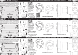
01 - Aprire le fotocellule (fig. 1-2); 02 - verificare il tipo di alimentazione for-
nita dalla Centrale dell’automatismo; 03 - spostare il ponticello elettrico del
TX e dell’RX, nella posizione adatta a selezionare la stessa alimentazione
presente nella Centrale (fig. 3); 04 - fissare sulla parete il coperchio poste-
riore delle fotocellule (fig. 4); 05 - eseguire i collegamenti elettrici in base
alla funzione desiderata, seguendo le istruzioni riportate nel manuale della
Centrale e nello schema di fig. 5; 06 - rimontare la parte anteriore delle
fotocellule (fig. 6-7).
5 - COLLAUDO
Ogni singolo componente dell’automatismo richiede una fase specifica di
collaudo. Per le fotocellule eseguire la seguente procedura:
01 - Verificare che siano state rispettate rigorosamente tutte le istruzioni
riportate in questo manuale. 02 - Alimentare la coppia di fotocellule e verifi-
care il loro allineamento confrontando lo stato del Led della fotocellula RX
(acceso o spento), con la Tabella 1. 03 - Se necessario, migliorare l’allinea-
mento orientando le fotocellule fino a quando il Led si spegne. 04 - Verifica-
re l’efficienza delle fotocellule e, in particolare, l’assenza di interferenze con
altri dispositivi (ad esempio, un’altra coppia di fotocellule installata nelle vici-
nanze), interrompendo l’asse ottico tra le due fotocellule con un cilindro del
diametro di 5 cm (prima vicino al TX, poi vicino all’RX e infine al centro tra i
due – vedere fig.8). Quindi, verificare che le fotocellule intervengano in tutti
i casi, passando dallo stato attivo a quello di allarme e viceversa; infine, che
provochino nella Centrale l’azione prevista sull’automatismo (ad esempio,
nella manovra di chiusura, che provochino l’inversione del movimento). 05
- Verificare la corretta rilevazione dell’ostacolo applicando la norma EN
12445, che prevede l’uso di un parallelepipedo di test (700 x 300 x 200
mm), con 3 lati in colore nero opaco e 3 lati in colore bianco lucido o a
specchio (vedere fig. 9).
6 - AVVERTENZE PER L’USO
• Le fotocellule non sono un dispositivo di sicurezza ma soltanto un dispo-
sitivo ausiliario alla sicurezza; nonostante siano costruite con tecnologia
affidabile, in situazioni estreme possono subire malfunzionamenti o gua-
starsi e, in certi casi, il guasto potrebbe non essere subito evidente. Per
questi motivi, e comunque per buona regola,
- il transito è consentito solo se il cancello o portone è completamente
aperto e con le ante ferme.
- È ASSOLUTAMENTE VIETATO transitare mentre il cancello o portone
si sta chiudendo!
• Prima di procedere alla pulizia del prodotto, sbloccare il motoriduttore
come descritto nel suo manuale istruzioni. Questo impedisce l’aziona-
mento involontario dell’automazione.
• Per la pulizia del prodotto, utilizzare un panno morbido e umido. Impor-
tante – non utilizzare liquidi contenenti alcool, benzene, diluenti o altre
sostanze infiammabili: questi possono danneggiare il prodotto e generare
incendi o scosse elettriche.
• Verificare periodicamente il corretto funzionamento delle fotocellule, effet-
tuando i controlli descritti nel capitolo “Manutenzione”.
7 - MANUTENZIONE
Eseguire la manutenzione ogni 6 mesi (minimo), effettuando le seguenti
operazioni: a - verifica di eventuali presenze di umidità, ossidazione, o altro;
b - pulizia dell’involucro esterno e delle lenti; c - nuovo collaudo come de -
scritto nel capitolo “Collaudo”.
Le fotocellule sono studiate per funzionare in condizioni normali almeno 10
anni; trascorso questo periodo è opportuno intensificare la frequenza degli
interventi di manutenzione.
CARATTERISTICHE TECNICHE
Tipo di prodotto: rilevatore di presenza per automatismi su cancelli e
portoni (tipo D secondo norma EN 12453) composto da un trasmettitore e
un ricevitore. Tecnologia adottata: interpolazione ottica diretta tra TX ed
RX, con raggio infrarosso modulato. Alimentazione: selezione con pon-
ticello: “12 V” = 12 Vac/dc (limiti 8-16 Vac, 9-17 Vdc); selezione con ponti-
cello: “24 V” = 24 Vac/dc (limiti 19-28 Vac, 17-35 Vdc). Corrente assor-
bita: 20 mA (TX), 25 mA (RX), 45 mA (in coppia). Capacità di rilevamen-
to: oggetti opachi posti sull’asse ottico tra TX ed RX, con dimensioni mag-
giori di 50 mm e velocità minore di 1,6 m/s. Angolo di trasmissione e di
ricezione: +/- 15° circa (valore rilevato al 50% della portata). Portata uti-
le: 8 m (il dispositivo può segnalare un ostacolo anche in caso di condizio-
ni meteorologiche particolarmente avverse). Portata massima: 20 m
(portata garantita in condizioni ottimali). Utilizzo in atmosfera acida,
salina potenzialmente esplosiva: NO. Montaggio: in verticale, a pare-
te o su colonna MPT5. Grado di protezione contenitore: IP44. Tem-
peratura di esercizio: -20° ÷ 50°C. Dimensioni / Peso (coppia): 50 x
85h x 35 mm / 140 g.
SMALTIMENTO DEL PRODOTTO
Questo prodotto è parte integrante dell'automazione e, dunque, deve
essere smaltito insieme con essa.
Come per le operazioni d'installazione, anche al termine della vita di questo
prodotto, le operazioni di smantellamento devono essere eseguite da per-
sonale qualificato.
Questo prodotto è costituito da vari tipi di materiali: alcuni possono essere
riciclati, altri devono essere smaltiti. Informatevi sui sistemi di riciclaggio o
smaltimento previsti dai regolamenti vigenti sul vostro territorio, per questa
categoria di prodotto.
Attenzione! – alcune parti del prodotto possono contenere sostanze inqui-
nanti o pericolose che, se disperse nell’ambiente, potrebbero provocare
effetti dannosi sull'ambiente stesso e sulla salute umana.
Come indicato dal simbolo a lato, è vietato gettare questo pro-
dotto nei rifiuti domestici. Eseguire quindi la “raccolta separa-
ta” per lo smaltimento, secondo i metodi previsti dai regola-
menti vigenti sul vostro territorio, oppure riconsegnare il pro-
dotto al venditore nel momento dell'acquisto di un nuovo pro-
dotto equivalente.
Attenzione! – i regolamenti vigenti a livello locale possono prevedere
pesanti sanzioni in caso di smaltimento abusivo di questo prodotto.
DICHIARAZIONE DI CONFORMITÁ CE
MPQ è prodotto da NICE S.p.a. (TV) I; MOOVO è un marchio commerciale di proprietà
di Nice S.p.a.
Nota: Il contenuto di questa dichiarazione corrisponde a quanto dichiarato nell’ultima revi-
sione disponibile, prima della stampa di questo manuale, del documento ufficiale deposi-
tato presso la sede di Nice Spa. Il presente testo è stato riadattato per motivi editoriali.
Numero: 289/MPQ Revisione: 0
Il sottoscritto Lauro Buoro in qualità di Amministratore Delegato, dichiara sotto la propria
responsabilità che il prodotto – nome produttore: NICE s.p.a.; indirizzo: via Pezza
Alta, 13 - Z.I. Rustignè, 31046 Oderzo (TV) Italia; tipo: fotocellula a relè serie “MOOVO”;
modelli: MPQ; accessori: MPT5, – risulta conforme a quanto previsto dalle seguenti
direttive comunitarie, così come modificate dalla Direttiva 93/68/CEE del consiglio del
22 Luglio 1993:
• 2004/108/CEE (ex direttiva 89/336/CEE) DIRETTIVA 2004/108/CE DEL PARLAMEN-
TO EUROPEO E DEL CONSIGLIO del 15 dicembre 2004, concernente il ravvicina-
mento delle legislazioni degli Stati membri relative alla compatibilità elettromagnetica e
che abroga la direttiva 89/336/CEE,
secondo le seguenti norme armonizzate: EN 61000-6-2:2005; EN 61000-6-
3:2001+A11:2004
Oderzo, 5 Maggio 2008 Lauro Buoro
(Amministratore Delegato)
ITALIANO FRANÇAIS
Tabella 1
Stato del Led Significato Stato uscita Azione
Sempre spento Segnale OK = Nessun ostacolo Attivo Nessuna (tutto Ok!)
Sempre acceso Segnale zero = Presente ostacolo Allarme Rimuovere ostacolo o migliorare l’allineamento
Tableau 1
Etat de la Led Signification Etat sortie Action
Toujours éteinte Signal OK = Aucun obstacle Activé Aucune (tout Ok!)
Toujours allumée Signal zéro = Présence d’un obstacle Alarme Enlever l’obstacle ou améliorer l’alignement
MPQ
Pair of photocells
5
1 2
6 7
4
Oderzo TV, Italy
Tel. +39 0422 20 21 09
Fax +39 0422 85 35 85
www.moovo.com
Moovo is a commercial
trademark owned by
Nice S.p.a.
Codice: IST260.4854 - Rev. 00 del 15-07-2008
EN Installation and use instructions and
warnings
IT Istruzioni ed avvertenze per
l’installazione e l’uso
FR Instructions et avertissements pour
l’installation et l’utilisation
ES Instrucciones y advertencias para la
instalación y el uso
DE Anweisungen und Hinweise für die
Installation und die Bedienung
PL Instrukcje instalacji i użytkowania i
ostrzeżenia
NL Aanwijzingen en aanbevelingen voor
installering en gebruik
Hotline technique exclusivement pour la France:
3
12V / 24V
8
9
Table 1
State of LED Meaning Exit state Action
Always off Signal OK = No obstacle Active None (everything Ok!)
Always on Zero signal = Obstacle present Alarm Remove obstacle or improve alignment
1 - MISES EN GARDE
1.1 - Mises en garde de sécurité
• ATTENTION! – Le présent manuel fournit d’importantes instructions
et mises en garde sur la sécurité des personnes. Une installation erro-
née peut causer de graves blessures aux personnes. Par conséquent,
avant de commencer le travail, il faut lire attentivement toutes les parties
de ce manuel et, en cas de doutes, demander des explications au Ser-
vice d’Assistance Moovo.
• ATTENTION! – Toutes les opérations d’installation, raccordement,
programmation et maintenance du produit ne doivent être effec-
tuées que par un technicien qualifié et compétent, dans le respect
des lois, des normes, des règlements locaux et des instructions
fournies dans ce manuel.
• ATTENTION! – Instructions importantes : conserver ce manuel pour
toute éventuelle intervention future de programmation, de mainte-
nance et d’élimination du produit.
Mises en garde particulières sur l’adéquation de ce produit à la Direc-
tive “Compatibilité Electromagnétique” 89/336/CEE et modifications
successives 92/31/CEE et 93/68/CEE.
Ce produit a été soumis à des tests de compatibilité électromagnétique
dans des situations critiques d’utilisation, dans les configurations prévues
dans ce manuel et en combinaison avec les articles présents dans le cata-
logue des produits Moovo.
Avec des configurations ou des produits non prévus, la compatibilité
électromagnétique n’est pas garantie ; par conséquent il n’est possible
d’utiliser le produit qu’après avoir vérifié qu’il réponde pleinement aux
conditions requises prévues par la directive.
1.2 - Mises en garde pour l’installation
Attention! – Le système ne doit fonctionner que par interpolation
directe
entre TX et RX : le fonctionnement par réflexion est interdit.
• Ne pas démonter le produit en dehors des opérations prévues dans ce
manuel. Toute opération non prévue peut causer des dysfonctionne-
ments et le fabricant décline toute responsabilité quant aux dommages
provoqués par des produits modifiés arbitrairement.
• Au cours de l’installation, manipuler le produit avec soin et éviter tout
écrasement, choc, chute ainsi que tout contact avec n’importe quel
liquide, source de chaleur et flamme nue. Ces situations peuvent endom-
mager le produit et causer des dysfonctionnement ou des dangers.
Dans de tels cas, débrancher immédiatement l’alimentation, suspendre
l’installation et s’adresser au Service d’Assistance Moovo.
• Il faut éliminer le matériel de l’emballage du produit conformément aux
normes locales.
2 - DESCRIPTION DU PRODUIT ET USAGE PREVU
Ce produit est un couple de photocellules à relais destiné aux installations
d’automatisation pour portes, portillons, portes de garage et équivalents.
ATTENTION! – Toute utilisation autre que celle décrite doit être consi-
dérée impropre et interdite!
Le couple se compose d’une photocellule qui transmet (TX) et d’une pho-
tocellule qui reçoit (RX), chacune étant identifiée par une étiquette dans le
couvercle. L’ensemble représente un dispositif auxiliaire à la sécurité car il
permet de détecter la présence d’un obstacle sur la trajectoire qui relie
TX et RX. Elles peuvent être installées sur un mur ou sur les colonnes
MPT5 (accessoire en option).
3 - VERIFICATIONS PREALABLES A L’INSTALLATION
• Vérifier sur la Centrale de l’automatisation que la tension d’alimentation
présente sur les bornes réservées soit compatible avec les données
reprises au chapitre “Caractéristiques techniques”.
• Vérifier que chaque photocellule soit installée dans une position
correcte, à l’abri de chocs accidentels et en mesure de permettre une
maintenance aisée.
• Vérifier que la superficie choisie pour l’installation garantisse une fixation
stable et ne transmette pas de vibrations à la photocellule.
Limites d’utilisation
Les photocellules peuvent être connectées exclusivement à des Centrales
avec entrées “Photo” de type traditionnel. Des limites d’utilisation supplé-
mentaires sont reprises au chapitre “Caractéristiques techniques”.
4 - INSTALLATION ET RACCORDEMENTS
Attention! • Avant d’effectuer les connexions électriques ou toute autre
opération qui requière l’ouverture de l’enveloppe de protection du produit, il
faut débrancher l’installation de l’alimentation électrique et de la batterie
tampon (si installée). D’autre part, si le dispositif de déconnexion ne se
trouve pas à la vue, il faut y fixer un panneau indiquant “ATTENTION! MAIN-
TENANCE EN COURS”. • Respecter scrupuleusement les connexions indi-
quées. Un raccordement erroné peut provoquer des pannes ou des situa-
tions de danger.
Procéder de la façon suivante :
01 - Ouvrir les photocellules (fig. 1-2) ; 02 - vérifier le type d’alimentation
fournie par la Centrale de l’automatisme ; 03 - déplacer le pontage élec-
trique du TX et du RX dans la position adéquate pour sélectionner la même
alimentation que dans la Centrale (fig. 3) ; 04 - fixer au mur le couvercle
arrière des photocellules (fig. 4) ; 05 - exécuter les connexions électriques
selon la fonction souhaitée, en suivant les instructions reprises dans le
manuel de la Centrale et sur le schéma de fig. 5 ; 06 - remonter la partie
avant des photocellules (fig. 6-7).
5 - TEST
Chaque composant individuel de l’automatisme requiert une phase spéci-
fique de test. Pour les photocellules, suivre la procédure suivante :
01 - Vérifier que toutes les instructions fournies dans ce manuel aient été
scrupuleusement respectées. 02 - Alimenter le couple de photocellules et
vérifier leur alignement en comparant l’état de la Led de la photocellule RX
(allumée ou éteinte), avec le Tableau 1. 03 - Si nécessaire, améliorer l’ali-
gnement en orientant les photocellules jusqu’à ce que la Led s’éteigne. 04
- Vérifier le bon fonctionnement des photocellules et, en particulier, l’ab-
sence d’interférences avec d’autres dispositifs (par exemple, un autre cou-
ple de photocellules installé à proximité), en interrompant l’axe optique
entre les deux photocellules à l’aide d’un cylindre d’un diamètre de 5 cm
(d’abord près du TX, ensuite près du RX et finalement au centre, entre les
deux – voir fig.8). Vérifier alors que les photocellules interviennent dans
tous les cas et passent de l’état activé à celui d’alarme et vice versa ;
et finalement, qu’elles provoquent dans la Centrale l’action prévue sur l’au-
tomatisme, (par exemple, au cours de la manoeuvre de fermeture, qu’elles
provoquent l’inversion du mouvement). 05 - Vérifier que l’obstacle soit cor-
rectement détecté en appliquant la norme EN 12445, qui prévoit l’utilisation
d’un parallélépipède de test (700 x 300 x 200 mm) dont 3 côtés doivent
être de couleur noire et 3 côtés de couleur blanche brillante ou réfléchis-
sante (voir fig. 9).
6 - MISES EN GARDE D’UTILISATION
• Les photocellules ne sont pas un dispositif de sécurité mais seulement un
dispositif auxiliaire à la sécurité ; bien qu’elles soient fabriquées avec une
technologie fiable, dans des situations extrêmes elles peuvent subir des
dysfonctionnements ou tomber en panne et, dans certains cas, la panne
pourrait ne pas être tout de suite évidente.
Pour ces raisons et de toute façon comme règle générale,
- le passage n’est permis que si la porte ou le portillon est ccomplète-
ment ouvert et que les battants soient arrêtés.
- IL EST ABSOLUMENT INTERDIT de passer pendant que la porte ou
le portillon est en train de se fermer!
• Avant de nettoyer le produit, débloquer le motoréducteur comme décrit
dans son manuel d’instructions. Ceci empêche l’actionnement involon-
taire de l’automatisation.
• Pour nettoyer le produit. Utiliser un chiffon souple et humide. Important –
ne pas utiliser de liquides contenant alcool, benzène, diluant ou d’autres
substances inflammables : ceux-ci peuvent endommager le produit et
1 - WARNINGS
1.1 - Security warnings
• ATTENTION! – This manual contains important instructions and
warnings for peoples’ safety. Mistakes in the installation can cause
serious injuries to people. Therefore, before starting work, it is neces-
sary to carefully read all parts of the manual and, if in doubt, ask
Moovo After-Sales Assistance for clarification.
• ATTENTION! – All installation, connection, programming and
product maintenance operations have to be carried out exclu-
sively by a qualified and skilled technician, in the full respect of
laws, standards and local rules and the instructions in this
manual.
• ATTENTION!
– Important instructions: keep this manual for
future interventions regarding programming, maintenance and
disposal of the product.
Special warnings regarding the suitability of use of this product in
relation to the 89/336/EEC “Electro-magnetic Compatibility” Direc-
tive and subsequent modifications 92/31/EEC and 93/68/EEC.
This product has been subject to electro-magnetic compatibility tests
during critical situations, in the configurations envisioned in this manu-
al and combined with the articles in the Moovo product catalogue.
The electro-magnetic compatibility is not guaranteed with configura-
tions or products not foreseen; therefore the use of the product is only
possible after having verified its full correspondence to the requisites
foreseen in the directive.
1.2 - Warnings regarding installation
Attention! – The system is for the exclusive use of direct
interpo-
lation between TX and RX: use is prohibited due to reflection.
• Do not dismantle the product in a different way to that specified in
this manual. Unforeseen operations can cause malfunctioning and
the builder refuses any responsibility for damages deriving from
products being modified arbitrarily.
• Manage the product carefully during installation, avoiding crushing,
blows, falls, contact with any liquid, heat or flames. These conditions
can damage the product and cause malfunctioning or danger. In
these cases, disconnect the power immediately, suspend the instal-
lation and contact the Moovo After-Sales Assistance.
• The packaging material has to be disposed of in compliance with the
local regulations.
2 - PRODUCT DESCRIPTION AND USE
This product is a pair of relay photocells for use in automated systems for
doors, gates, garage doors and similar. ATTENTION! – Any use different
to that specified is to be considered improper and forbidden!
The pair is formed by a photocell that transmits (TX) and one that
receives (RX), each identified by a label inside the lid. Together they
work as an auxiliary safety device as they show the presence of an
obstacle on the trajectory that joins TX and RX. They can be fitted to
walls or on MPT5 columns (optional accessory).
3 - INSPECTIONS BEFORE INSTALLING
• Verify on the automatism control unit that the power supply voltage
present on the dedicated clamps is compatible with the data in the
“Technical features” chapter.
• Verify that each photocell is in a protected position, sheltered from
accidental blows and which allows easy maintenance.
• Verify that the surface chosen for installation guarantees stable fixing
and does not transmit vibrations to the photocell.
Limits for use
The photocells can be connected exclusively to Control units with tra-
ditional “Photo” inputs. Further limits are quoted in the “Technical fea-
tures” chapter.
4 - INSTALLATION AND CONNECTONS
Attention! • Before carrying out the electrical connections or other
operations which require the opening of the product’s protective cas-
ing, the plant must be disconnected from the power supply and from
the buffer battery (if present). Moreover, if the disconnection device
cannot be seen, apply a sign saying “ATTENTION! MAINTENANCE IN
PROGRESS”. • Scrupulously respect the indicated connections. An
incorrect connection can cause breakdown or dangerous situations.
Proceed in the following manner:
01 - Open the photocells (fig. 1-2); 02 - check the type of power sup-
plied from the automatism control unit; 03 - move the electronic
jumper of the TX and RX into the correct position for selecting the
same power supply that is present in the control unit (fig. 3); 04 - fix
the back cover of the photocells onto the wall (fig. 4); 05 - following
the instructions in the Control unit manual and the diagram in fig.
5,carry out the electrical connection according to the desired function;
06 - reassemble the front part of the photocell (fig. 6-7).
5 - INSPECTION
Each single component of the automatism requires specific testing.
For the photocells perform the following procedure:
01 - Check that all instructions given in this manual have been fol-
lowed. 02 - Supply power to the pair of photocells and check their
alignment comparing the state of the RX photocell LED (on or off), with
Table 1. 03 - Improve the alignment, if necessary, by orientating the
photocells until the LED switches off. 04 - Check the efficiency of the
photocells, and in particular, the absence of interference with other
devices (for example, another pair of photocells installed nearby), inter-
rupting the optic axis in between the two photocells using a 5 cm cylin-
der (first near TX, then near RX and then in between the two – see
fig.8). Then, check that the photocells work in all cases, going from
active to alarm and vice-versa; finally, that they cause the envisioned
action on the automatism in the control unit (for example, that whilst
closing, it re-opens). 05 - Check it recognises the obstacle correctly
by applying the EN 12445 rule, which envisions the use of a test paral-
lelepiped (700 x 300 x 200 mm), with 3 sides coloured matt black and
3 sides coloured polished white or with mirror (see fig. 9).
6 - WARNINGS REGARDING USE
• The photocells are not a safety device but only an auxiliary device for
safety; even if made with reliable technology, in extreme situations
they may suffer malfunctioning or breakdown and in certain cases
these breakdowns may not be immediately evident.
For these reasons and good practice,
- transit is only allowed if the gate or door is completely open and
the shutters are at a standstill.
- IT IS FORBIDDEN to transit whilst gate or door is closing!
• Release the geared motor, as described in the instructions manual,
before cleaning the product. This will prevent involuntary start-up of
the automation.
• Use a soft and humid cloth to clean the product. Important – do not
use products containing alcohol, benzene, thinners or other flamma-
ble substances: these can damage the product or cause fires or
electric shock.
• Periodically verify the correct functioning of the photocells by carry-
ing out the tests described in the “Maintenance” chapter.
7 - MAINTENANCE
Carry out maintenance at least every 6 months, as follows: a - check
the presence of humidity, oxidation, or other; b
- clean the outer casing
and the lenses; c - new testing as described in the “Testing” chapter.
The photocells have been conceived to work for at least 10 years
under normal conditions; after this time, it is a good idea to increase
the number of maintenance interventions.
1/2