SEA SWING 2 Manuale del proprietario
- Categoria
- Gate Opener
- Tipo
- Manuale del proprietario

REV 09 - 07/2010
SWING 2
SEA s.r.l.
Zona Ind.le S. Atto - 64020 S. Nicolò a Tordino (TE)
Tel. 0861.588341 - Fax 0861.588344
Numero Verde: 840.000.440
www.seateam.com
e-mail: [email protected]
67410670
ELECTRONIC CONTROL UNIT FOR SWING GATES
23021090 / 23021095
English
Sistemi Elettronici
di Apertura Porte e Cancelli
International registered trademark n. 804888
®
e
a
o
s
l
o
All
g
t
f
a ci
c
o
A
R E
NZE
V
VE T
ER I
GEN AL

SWING 2
COMPONENTS DECRIPTION .....................................................................................................3
CONNECTIONS............................................................................................................................4
GENERAL INFORMATION ..........................................................................................................5
FUNCTION LOGICS SETTING (DIP-SWITCH)............................................................................6
ADDITIONAL FUNCTIONS (DIP-SWITCH) ..................................................................................7
MOTOR TORQUE ADJUSTMENT................................................................................................8
TIME OF SLOWDOWN ADJUSTMENT........................................................................................8
PAUSE TIME ADJUSTMENT / LEAF DELAY IN WORKING TIMES MODE.................................8
ENCODER SENSITIVITY ADJUSTMENT / WORKING TIMES....................................................8
ALARMS INDICATIONS TABLE....................................................................................................8
PALM FUNCTIONS.......................................................................................................................8
START, STOP, PEDESTRIAN START, ANTENNA, PHOTOCELLS, ELECTRIC LOCK
CONNECTIONS............................................................................................................................9
POWER SUPPLY AND MOTOR CONNECTIONS......................................................................10
ENCODER (SAFETY GATE) MANAGEMENT ACTIVATION ......................................................11
SAFETY GATE (ENCODER), FLASHING LAMP CONNECTIONS ............................................11
WORKING TIMES SELFLEARNING ON SWING GATE ............................................................12
WORKING TIMES ADJUSTMENT WITH TRIMMER ON SWING GATE....................................15
RADIO TRANSMITTERS MEMORIZING....................................................................................16
RADIO TRANSMITTERS CANCELLATION................................................................................16
SAFETY LOOP CONNECTION ..................................................................................................17
TROUBLE SHOOTING ...............................................................................................................18
WARNINGS AND GUARANTEE.................................................................................................19
INDEX
Italiano
English
Sistemi Elettronici
di Apertura Porte e Cancelli
International registered trademark n. 804888
®
67410670 REV 09 - 07/2010
2

SWING 2
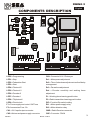
LEDP = Programming
LED1 = Stop
LED2 = Pedestrian Start
LED3 = Start
LED4 = Photocell 2
LED5 = Photocell 1
LED6 = Encoder 2
LED7 = Encoder 1
LED8 = TXphotocell
LED9 = Electric lock
F1 = Power supply and motor 6.3AT fuse
F2 = Accessories Fuse 2A
CN1 = 24 V input/output connector
CN2 = Motors and power supply connector
COMPONENTS DESCRIPTION
English
Sistemi Elettronici
di Apertura Porte e Cancelli
International registered trademark n. 804888
®
CN1 CN2
RL1
RL2
F1
F2
P1
P2
Rv1
Rv2
Rv3
U1
U2
DIP
LED5
LED8
LED9
LEDP
LED2
LED3
LED4
Rv4
LED1
LED6
LED7
CMR
CNP
CN3
CN3= Connector 24 V~ Photosync
Rv1 = Motor power adjustment
Rv2 = Time of slowdown adjustment and leaf delay
management
Rv3 = Pause time adjustment
Rv4 = Encoder sensitivity and working times
adjustment
P1 = Working times learning push-button
P2 = Radio transmitters learning push-button
DIP = Function Dip-switch setting
RL1 = Motor power supply relay
RL2 = Motor direction relay
CMR = Radio Receiver connector
CNP= Connector PALM
67410670 REV 09 - 07/2010
3

SWING 2
CN1
CN2
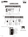
CONNECTIONS
Operation logics
Photocells selftest
Slowdown
Leaf locking
Reverse stroke
Selflearning
11 22 33 44 55 66 77 88
ONON
ON= Active function
DIP
M2
~
Op
e in
g
n
C
l
o
s
in
g
Co
m
m
o
n
p t r
Ca a
c
i o
M
2
N
e
u
t
r
a
l
i
L n
e
1 2 3 4 5 6 7 8 9 10 1112 13 14 15
p t
r M
C
a
a
ci
o
1
M1
~
O
p
e
n
in
g
Cl
si
n
g
o
C
o
m
m
o
n
a
p
Fl
a
s
h
i
n
g
l m
2
3
0
V
5
0
W
m
a
x
Encoder
1 2 3 4 5 6 7 8 9 10 1112
P
ho
t
o
c
e
ll 24V
TX
l
t
r
l
kE ec
i
c
oc
2
P
hot
o
c l
l
e
r a
P
e
d
es
t
i
n
S
TART
S
T
O
P
Com
mo
n
neAtnna
T
A
S
R
T
1
Pho
to
c ll
e
E
n o
d
r
2
c
e
En
od
r
1
c
e
Cm
o
omn
i
L n
e
N
e
u r
l
t a
Pre - flashing
Note: Bridge all unused N.C. contacts.
English
Sistemi Elettronici
di Apertura Porte e Cancelli
International registered trademark n. 804888
®
CN3
1 2
24 V~
4
2
V
Note: to power supply
the syncronized photocells.
67410670 REV 09 - 07/2010
4

GENERAL INFORMATION
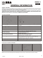
GENERAL FEATURES
SWING2 control unit has been deigned in order to manage one or two swing operators without limit switch. Its dimensions are
very small, four different operation modes, possibility to adjust many parameters using the trimmer and dip switch, in addition
the possibility to manage the use of the encoder through the safety gate device.
The absolute news of such electronic unit consists in two different learning modes of working times. Besides the
standard and intuitive selflearning mode of working times (the same for GATE2), it gives the possibility to learn
MANUALLY the working times, acting simply on TRIMMER Rv4 ADJUSTMENT.
TECHNICAL FEATURES
Control unit power supply
Transformer
Absorbed power
Max. motor charge
Max. accessories charge
Max. flashing light charge
Environment temperature
Protection fuses (24V accessories)
Programming modes
Operating logics
Opening / closing time
Pause time
Thrust force
Slowdowns
Leaf delay
Encoder sensitivity
Connecting terminal entries
Connecting terminal exits
Board dimensions
Outside box features
SWING 2
ACCESSORES TECHNICAL FEATURES
Kind of accessories Inom absorbed (stand by)
SIGNAL receivers 15 mA each
PHOTO 50 55 mA each couple
PHOTO 60 108 mA each couple
GHOST 40 60 mA each couple
GHOST 50 60 mA each couple
SLIM 95 mA each couple
Kind of accessories Inom absorbed (stand by)
KEY PLUS START-STOP 10 mA
CODE + MODULE DEC. 12 mA
CODE PLUS 6 mA
THERMO 15 mA
LOOP 16 mA
RADIODEC PROX 150 mA
NOTE: the sum of the nominal power absorbed by the each accessory on 24V exit must not exceed 200 mA.
English
Sistemi Elettronici
di Apertura Porte e Cancelli
International registered trademark n. 804888
®
67410670
230V ~ (+6 -10%) - 50/60 Hz
P1: Vn=230V , Io=43.3 mA; S1: Vnom=17.5V , Vo=20.2V , I=0.69A
7,5 W
500 W x 2
24V 200mA
230V 50W max.
-20°C +50°C
1 A
Selflearning page 12; instructions manual including TRIMMER page 15
Automatic / Semi-automatic / safety automatic / safety Semi-
automatic
Adjustable with trimmer until 120 s
Adjustable with trimmer from 0 to 120 s
Adjustable with trimmer
Adjustable with trimmer
Selflearning mode during programming phase.
During working times mode adjustable with trimmer
Only during selflearning mode,
Adjustable with trimmer
Antenna / Stop / Start / pedestrian Start /
photocells 1 and 2 / Encoder 1 and 2
Power supply accessories 24V / Motors 230V 500W x 2 /
Flashing light 230V 50W / Electric lock 12V 15VA max/
TX photocell power supply 24V / Capacitor
150,7 x 141 x 47,5 mm
305 x 225 x 125 mm - Ip55
~~~
~
REV 09 - 07/2010
5

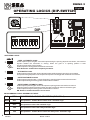
OPERATING LOGICS
- SEMI - AUTOMATIC LOGIC
- AUTOMATIC LOGIC
A start impulse opens the gate. A second impulse during the opening stops the movement, a successive
impulse restarts the movement in closing. When the gate is in opening position a start
impulse is required for closing it again.
A start impulse in closing phase reverses the movement.
Note: Rotate the trimmer Rv3 completely clockwise.
A start impulse opens the gate. A second start impulse while the gate is opening is not accepted.
An impulse during the pause is not accepted. An impulse in closing phase reverses the movement.
- SAFETY AUTOMATIC LOGIC
A start impulse opens the gate. A second impulse in opening phase reverses the movement.
A start impulse during the closing phase reverses the movement.
- SAFETY SEMI - AUTOMATIC LOGIC
A start impulse opens the gate. A second impulse in opening phase reverses the movement.
When the gate is in opening position another impulse is required in order to reclose the gate.
A start impulse during the closing phase reverses the movement.
NB: Ruotare il trimmer Rv3 tutto in senso orario
OFF
FUNCTIONING LOGICS SELECTION (DIP1 E Rv3)
DIP1 position + Trimmer Rv3 to select semi - automatic logic
Rv3
MAX
ON
OFF
DIP1 position to select the automatic logic
DIP1
DIP1 position to select the safety automatic logic
MAX
ON
DIP1 position + Trimmer Rv3 to select the safety semi - automatic logic
SWING 2
DIP
1 2 3 4 5 6 7 8
ON
DIP
Rv3
Rv3
+-
+
ONON
Rv3
MAX
11 11 11
+
Rv3
MAX
11
PROGRAMMING LOGICS: SUMMING UP TABLE
OPERATING LOGICS (DIP-SWITCH)
English
Sistemi Elettronici
di Apertura Porte e Cancelli
International registered trademark n. 804888
®
67410670 REV 09 - 07/2010
6

SWING 2
ON
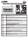
SETTING OF THE OTHER FUNCTIONS THROUGH DIP-SWITCH
PRE - FLASHING
When this function is activated the flashing lamp begins flashing about 3 seconds before the motor
starts to work, both in closing and opening.
DIP
2
POSITION
ON
SELFTEST PHOTOCELL
When this function is activated a test is executed on the photocells before the gate starts to move. In
order to enable this function the photocells transmitters must be connected to terminals 11 (24V) and
2 (Negative) of connector CN1.
The selftest can be exclusively used with the imput photocell 1.
3
ON
ENCODER MANAGEMENT (only in working times selflearning mode)
When this function is activated, the impulses coming from an encoder placed on the motor or on the
gate are managed, so that any obstacle which interrupts the passage can be detected and the gate
reverses its movement.
If a malfunctioning occurs, the flashing lamp will execute a sequence of 3 flashings.
After every single intervention the gate proceeds at reduced speed until it reaches the positive stop.
NOTE: if no encoder is installed, place DIP to OFF position.
Note: The Encoder sensibility can be adjusted through the PALM or through the pushbuttons
Ptime and Pcode on board of the control unit.
4
ON
SLOWDOWN AND LIMIT SWITCH
When this function is activated motor speed reduces slowly before the gate reaches the limit switch
stop or before the operating time ends.This function is designed in order to get the leaf gently closer
to the mechanical stops, avoiding any noisy clash. The closing speed is fixed, while the slowdown
time can be adjusted using the trimmer Rv2.
5
ON
6
ON
REVERSING STROKE
This function (to be used exclusively on swing gates) is useful to facilitate the electric lock release.
At the start impulse the leaves in closing phase are powered for 1 second approximately, before the
opening cycle starts..
7
DIP
1 2 3 4 5 6 7 8
ON
DIP
ON
WORKING TIMES ADJUSTMENT USING TRIMMER
This DIP when on ON position allows to activate the adjustment of the working times with trimmer,
de-activating the selflearning.
8
ADDITIONAL FUNCTIONS (DIP-SWITCH)
English
Sistemi Elettronici
di Apertura Porte e Cancelli
International registered trademark n. 804888
®
LEAF LOCKING
When this function is activated, at the end of slowdown phase, and when the leaf has reached the
mechanical stop, the motor is supplied at maximum power for 1 second approximately. This
increases the oil pressure in the motor and makes the hydraulic lock more effective.
WARNING: this function must not be activated on a sliding gate since it could cause the over
- running of the limit switches, with following block of the automation.
(Through the PALM it is possible to exclude the PUSHOVER in opening).
67410670 REV 09 - 07/2010
7

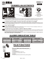
Control unit SWING 2 with PALM administration
• Visualisation and modification of the following parameters:
• Working times
• Leaf delay
• Partial opening time
• 2 n. maintenance cycles adjustment
• Antisqueezing sensibility SAFETY GATE
• PhotoStop
• PhotoClose
• PushOpen ( excludes the pushover during opening phase)
PALM FUNCTIONS
SWING 2
ALARMS INDICATION TABLE
The flashes sequence,spaced with a pause, is showed on the flashing lamp (for about 20 seconds) .and on the control lamp
Flashes number
1
3
Kind of alarm
Photocell
Encoder
Flashes number
4
5
Kind of alarm
Stop
Photocell selftst
English
Sistemi Elettronici
di Apertura Porte e Cancelli
International registered trademark n. 804888
®
CN3CN2
RL1
RL2
CN4
RL3
F1
F2
P1
P2
Rv1
Rv2
Rv3
CN1
U1
U2
DIP
J1
LED5
LED6
LED7
LED8
LED9
LED10
LED11
LED1
LED2
LED3
LED4
LED12
LED13
LED14
LED15
LED16
TRIMMER ADJUSTMENTS
MOTOR TORQUE ADJUSTMENT
This trimmer allows to adjust the thrust force of the motor reducer. This kind of adjustment is required for operators
without mechanical / hydraulic device for power limitation. The adjustment must be executed so that there is no
crushing danger for people or objects and in any case in accordance with the law in force on the matter.
SLOWDOWN TIME ADJUSTMENT / LEAF DELAY IN WORKING TIMES MODE WITH TRIMMER
This trimmer has a double functionality depending on the selected working mode. In working times selflearning mode
it allows to adjust the length of slowdown time. In working times manual adjusting mode (DIP 8 to ON position) this
trimmer manages the leaf delay.
PAUSE TIME ADJUSTMENT
This trimmer allows the linear adjustment of pause time from 0 to 120 s (If you rotate it completely clockwise, you
can adjust the working logics setting it in half-automatics).
ENCODER SENSITIVITY ADJUSTMENT / WORKING TIMES WITH TRIMMER
This trimmer has a double functionality depending on the selected working mode. In working times selflearning mode
it allows to adjust the encoder sensitivity, In working times manual adjusting mode (DIP 8 to ON position), this trimmer
manages the opening and closing time of the automation.
Note: The Encoder must be set following the laws in force. The maximum sensitivity is obtained with the
trimmer Rv4 completely in clockwise position.
Rv4
Rv3
Rv1
Rv2
Rv1
+
-
NOTE:
ROTATING THE
TRIMMER
CLOCKWISE
THE TIMES / VALUES
INCREASE
Rv2
Rv4
Rv3
67410670 REV 09 - 07/2010
8

10 11 12
1 2 3 4 5 6 7 8 9
-
C
SWING 2
2
4
2
5
CN1
-
1
2 3
2
12
+
-
TX
RX
102
Com
N.C.
6
+
-
TX
RX
102
Com
N.C.
7
C C
+ +
English
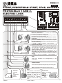
START, PEDESTRIAN START, STOP, ANTENNA
PHOTOCELLS 1 AND 2,
ELECTRIC LOCK
Start
This entry manages the opening/closing of the
automation.
Pedestrian Start
It executes complete opening/closing of one only leaf.
Note: The partial opening is executed on motor 1.
Photocell
Selftest
* optional
Antenna
Connect
the
antenna as
in the
picture.
Stop
The pressure of this button
stops the automation at any
time. A START impulse is
required in order to re-
establish the movement.
If not used put a jumper
between contact 3 and 2 of
CN1.
2 shield
Sistemi Elettronici
di Apertura Porte e Cancelli
International registered trademark n. 804888
®
Photocells 1 Connection
When the photocells beam is crossed, the automation
reverses its movement if in closing phase.
To use the photocells self- testing connect the (+) of the TX
photocell 1 with contact 11 instead of 10.
Note: When not used make a jumper between contact 7
and 2 of Cn1.
Note: With the PALM device it is possible to set this
photocell as PHOTOCLOSE, that means, that if occupied
during the pause, the automation interrupts the same and
recloses immediately.
+ = 24V - = 0V C = Contact Com = Common
Photocells 2 Connection
When the photocells beam is crossed, the automation reverses
its movement if in closing phase. In opening it causes the stop
of the gate until it is occupied, when released the gate returns
into open postion. Note: When not used make a jumper
between contact 6 and 2 of Cn1.
Note: With the PALM device it is possible to set as
PHOTOSTOP, that means that it does not allow to the gate
to open, while it does not intervene during the remaining
opening.
+ = 24V - = 0V C = Contact Com = Common
Electric lock
Note: it’s possible to connect
only one
electric lock.
12V
15VA max
67410670 REV 09 - 07/2010
9

10 11 12 13 14 15
1 2 3 4 5 6 7 8 9
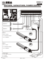
CN2
Example
Motor 2
Motors 2 outputs
M = OPENING/CLOSING
Com = COMMON
M1
M2
Capacitor 1
Capacitor 2
Com
N
Power supply
Power supply connection:
P = PHASE
N = NEUTRAL
M M
SWING 2
3
2
8
7
4 5 6
16
9
10
11
16
15
14
Com
M M P
MOTORS, CAPACITORS, POWER SUPPLY
Example
Motor 1
Motor 1 outputs
M = OPENING/CLOSING
Com = COMMON
English
Sistemi Elettronici
di Apertura Porte e Cancelli
International registered trademark n. 804888
®
67410670 REV 09 - 07/2010
10

CN1 CN2
10 11 12
1 2 3 4 5 6 7 8 9
SAFETY GATE
SAFETY GATE
SWING 2
2 108
2
9
10
-
+
12
13
CN2
10 11 12 13 14 15
1 2 3 4 5 6 7 8 9
Working with DIP 4 placed to ON position and exclusively in working
times self-learning mode.
ENCODER (SAFETY GATE)
MANAGEMENT ACTIVATION
After executing the four programming steps of the card, after connecting the encoder of both the motors and
executing themotor torque adjustments using trimmer RV1 and/or mechanical adjustment devices (by-pass
valves), place DIP 4 to ON position and repeat the programming procedure.
If necessary it’ s possible to disable the SAFETY GATE management placing DIP 4 to OFF position, without
repeating the self-learning times procedure.
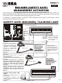
SAFETY GATE (ENCODER), FLASHING LAMP
Encoder 2
The encoder (Safety Gate) is a
system for obstacles
detection. It is set in the factory
on a middle level but can be
modified. Low sensibility
levels do not allow a fast
inversion as required by the
En12453 rules.
Connect the encoder 2 as in
the picture.
NOTE: Only in
working times
selflearning
mode (DIP8 OFF
and DIP4 ON)
Encoder 1
The encoder (Safety Gate) is a system for
obstacles detection.
Connect the encoder 1 as in the picture.
The Encoder function can be used in single leaf
modality.
Note: With the PALM device or through the
Trimer Rv4 on board of the control unit. it is
possible to adjust the sensibility of the
encoder on a scale from 0 to 15, where 0
indicates the max. sensibility during the
inversion.
Note: Every time when there is no current
supply and after every osbstacle the
automation, when no limit switches are
installed, will proceed slowly until it reaches
the stop.
Note: Only in
working times
selflearning mode
(DIP8 OFF and
DIP4 ON)
Flashing lamp (230V 50W
MAX)
Connect the flashing lamp as in
the picture.
It’s possible to ebable a pre-
flashing of 3 seconds putting DIP2
to ON position.
~
Brown
White
White
Green
English
After an Encoder
intervention and in case
of power supply failure,
the leaves will proceed at
reduced speed until they
reached their referring
stops.
Sistemi Elettronici
di Apertura Porte e Cancelli
International registered trademark n. 804888
®
1
2
Antenna
Connect
the antenna
as in the
picture.
The sensibility of the
encoder is adjustable
through the Trimmer
Rv4 on board of the
unit, see pag.8.
67410670 REV 09 - 07/2010
11

SWING 2
M1 M2
O
F
F
O
N
1 2 3 4 5
Example
Release
Example
Lock
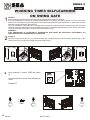
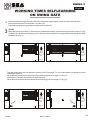
PHASE 1
Make all the electrical connections and take care to bridge all the unused N.C. contacts.
If you are installing a motor reducer equipped with mechanical / hydraulic anticrushing device, set the motor torque
(trimmer Rv1) at maximum value and make the motor torque adjustment using the appropriate by-pass valves or clutch
adjustment screws located on the operators.
If you are installing a motor reducer not equipped with mechanical / hydraulic power limitaiton device,set the motor
torque at maximum value ONLY during the selflearning phase. Immediately afterwards set a motor torque value which
can assure the anticrushing safety, in accordance with the law in forcei.
WARNING !
THIS PROCEDURE IS POTENTIALLY DANGEROUS AND MUST BE EXECUTED EXCLUSIVELY BY
SPECIALIZED STAFF UNDER SAFETY CONDITIONS.
PHASE 2
Disconnect the power supply (Fig. 1), release the gate (Fig. 2) and place the leaves at half-open position (Fig. 3). Re-
lock the motor (Fig. 4) and connect again the power supply (Fig. 5).
2
1
WORKING TIMES SELFLEARNING
ON SWING GATE
English
Sistemi Elettronici
di Apertura Porte e Cancelli
International registered trademark n. 804888
®
Keep pressed P1 button, LEDP will switch
on.
Keep pressed P1 until the motor M2 starts to
close*.
Release P1.
P1
LEDP
P1
M2M1
P1
67410670 REV 09 - 07/2010
12

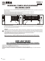
FASE 3
Motor M2 closes (from step 2), when the leaf reaches the closing mechanical stop press the button P1 (Fig.
6). Motor M1 will also start a closing cycle. When the leaf reaches the closing mechanical stop press again
the button P1 (Fig. 7).
3
The gate stops and motor M1 starts an opening cycle. Press agin P1 in the point where you desire to set the
leaf delay in opening.
When the leaf reaches the mechanical stop in opening press once again P1 (Fig. 8).
At this point motor M2 also will start an opening cycle.
When the leaf will reach the mechanical stop in opening push once again P1 (Fig. 9).
If the motos starts to open the gate, disconnect the power supply again, and reverse the motor phases.
Execute the same kind of connection on motor M1.
Repeat the programming procedurerogrammazione (fase 2).
Fig. 6
P1 P1
M2M1
Fig. 7
M2M1
Fig. 8
P1 P1
M2M1
Fig. 9
M2M1
SWING 2
WORKING TIMES SELFLEARNING
ON SWING GATE
English
Sistemi Elettronici
di Apertura Porte e Cancelli
International registered trademark n. 804888
®
*
67410670 REV 09 - 07/2010
13

Motor M2 will start automatically a closing cycle.Press again P1 in the point where you desire to set the leaf
delay in closing.
When the leaf reaches the mechanical stop in closing press once again P1 (Fig. 10).
At this point motor M1 will also start a closing cycle.
When the leaf reaches the mechanical stop in closing press once again P1 (Fig. 11).
Programming is finished.
Check the correct times memorizing giving a start impulse or pressing the button P1. If necessary repeat
the same learning procedure from step 2.
P1 P1
Fig. 10
M2M1
M2
M1
Fig. 11
PHASE 4
In case of use use with motor reducer without mechanical / hydraulic device for motor torque limitation,
adjust trimmer Rv1 on values which can assure the anti-crushing safety in accordance with the law in force.
If after adjusting the motor torque the working time is not enough (the leaf doesn’t open / close completely),
repeat STEP 2 setting the motor torque value as for the usual use of the automation.
Adjust the slowdown time (if enabled), using trimmer Rv2.
NOTE: assure that, in SAFETY GATE assistance (Encoder), DIP 4 is placed to OFF position.
4
SWING 2
WORKING TIMES SELFLEARNING
ON SWING GATE
1) Connect motors cables to terminals No. 9,10,11 of Cn2 terminal board
2) Move to zero TRIMMER Rv2 of leaf delay
3) Place to ON position dip8 (working times adjustment mode using trimmer)
4) Execute working times adjustment as explained in the related paragraph at page 15 of the instructions
manual.
ONE LEAF MODE
(ONLY IN WORKING TIMES ADJUSTMENT MODE USING TRIMMER )
English
Sistemi Elettronici
di Apertura Porte e Cancelli
International registered trademark n. 804888
®
67410670 REV 09 - 07/2010
14

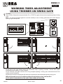
WORKING TIMES ADJUSTMENT
USING TRIMMER ON SWING GATE
SWING 2
PHASE 1
Place DIP8 to ON position and press button P1 or START, the gate will execute a complete opening / closing
cycle.
Note: It is strongly advised against to use this modality in case of swing gates with leaves with different
opening angles and speeds.
1
At this point if the gate doesn’t reach the mechanical stop in opening, increase trimmer Rv4 (rotate
clockwise) and give again a START impulse.
On the contrary, if the gate executes a too long complete opening / closing cycle, decrease trimmer Rv4
(rotate counter clockwise).
Repeat the procedure until the gate will reach the complete and requested opening and closing cycle.
When this mode is on it’s possible to adjust the leaf delays using trimmer Rv2.
NOTE: WHEN THIS MODE IS ON THE USE OF ENCODERS IS DISABLED.
8 1 2 3 4 5 6 7
ON
M2M1 M2M1
M2M1
M2
M1
Rv4
English
Sistemi Elettronici
di Apertura Porte e Cancelli
International registered trademark n. 804888
®
67410670 REV 09 - 07/2010
15

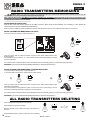
ALL RADIO TRANSMITTERS DELETING
Press and kepp pressing the button P2 (PCode).
LEDP will start a sequence of flashes.
Wait that the led stops to flash and release the button P2
(PCode).
P2
LEDP
P2
LEDP
LEDP will flash 6 times in order to confirm the correct deleting.
RADIO TRANSMITTERS MEMORIZING
WARNING: Make the radio transmitters programming before you connect the antenna and insert the receiver into the
special CMR connector (if available) with turned off control unit.
Note: With RF Roll module ( it will be possible to use only Coccinella Roll radio
transmitters.
Make sure that on CMR connector is installed the receiver with the same frequency of the radio transmitter that you want to use.
Press the button P2 (PCode). LEDP will switch on.
If no further code is memorized within 10 s the led will switch off automatically, getting out of the memorizing procedure
, it will be deleted (4 flashes).
Press the button P2 (PCode). LEDP will switch on.
2) Press the button P1 (PTime). LEDP will start to flash quickly.
If no further code is memorized within 10 s the led will switch off automatically, getting out of the memorizing procedure
, it will be deleted (4 flashes).
433 Mhz Cod. 23120470, 868 Mhz Cod. 23120480)
To use the 12bits remote controls, i.e. Ladybird Dip and COPY, SMART DUAL and Head it is necessary to purchase
the appropriate radio Kit (code 23120422).
RADIO MODULE CONNECTION
Plug the RF or RF Roll receiver module to the CMR connector. When using the Kit 23120422 it is necessary to, also replace the
microprocessor on the control unit (delivered with the kit).
RADIO TRANSMITTER MEMORIZING TO START
.
WARNING: if you enter a code which is already memorized
RADIO TRANSMITTER MEMORIZING TO PEDESTRIAN START
1)
.
WARNING: if you enter a code which is already memorized
Give an impulse with the radio transmitter, using the button which will be linked to the
pedestrian start impulse.
The Led will execute 2 long flashes in order to confirm the correct memorizing of Tx and
afterwards it will keep switching on waiting for new transmitters.
SWING 2
Give an impulse with the radio transmitter, using the button which will be linked to the
START impulse.
The led will execute two flashes Tx code and afterwards it will keep switching on waiting
for new transmitters.
P2
P2P2
LEDP
LEDP
P1
LEDP
P2
1) 2)
LEDP
LEDP
English
Sistemi Elettronici
di Apertura Porte e Cancelli
International registered trademark n. 804888
®
67410670
!!
REV 09 - 07/2010
16

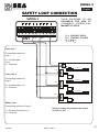
Loop 1
Loop1
Loop2
Loop3
10 11
1 2 3 4 5 6 7 8 9
-
C1
CN1
C2
THIS SCHEME IS AN
EXPAMPLE FOR HOW TO
CONNECT EVENTUAL
MAGNETIC LOOPS.
SWING 2
SWING 2
Note: In reality all contacts can be set
as N.O. or N.C.
+
English
SAFETY LOOP CONNECTION
Loop exit 1
Connecting scheme of
loop 1
5 = Contact start
(n.o.)
2 = Common
Loop exit 2
Connecting scheme of
loop 2
5 = Contact start (n.o.)
2 = Common
Safety loop
Connecting scheme of loop 3
7 = Contact photocell (n.c.)
2 = Common
Loop 2
Loop 3
Sistemi Elettronici
di Apertura Porte e Cancelli
International registered trademark n. 804888
®
C1 = CONTACT OPEN
C2 = CONTACT CLOSED
10 = 24 V
2 = 0 V
67410670 REV 09 - 07/2010
17

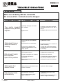
Advises
Problem
F ound
Possible
Make sure all Safety LED are turned ON
TROUBLE SHOOTING
All not-used N.C. Contacts must be bridged
Cause
Solutions
The motor doesn’t
respond to any START
impulse
a.) Bridge missing on one of the
N.C. contacts
b.) Burnt fuse
a.) Check connections or bridges
on contacts 2/6 on the Cn1, 2/7 on
the Cn1
b.) Replace burnt fuse on the board
Gate doesn’t move
while the motor is
running
a.) The motor is in the released
position
b.) Trimmer Rv1 is at minimum
c.) There is an obstacle or an
obstacle is detected but it is not
really present
a.) Re/lock the motor
b.) rotate Trimmer Rv1 at maximum
(rotate clockwise)
c.) Look and remove the obstacle
If encoder function is on, decrease
its sensitivity
Gate doesn’t reach
the complete
open/close position
a.) Programming error
b.) Gate is stopped by an obstacle
c.) The fiting geometry is
inadequate
d.) In manual adjusting mode with
trimmer Rv4
a.) Repeat the programming
b.) Remove the obstacle
c.) Check fitting geometry following
the operator installation manual.
d.) Rotate Trimmer Rv4 clockwise
Gate opens bur
doesn’t close
a.) Photocells connections 2/6 and
2/7 are not closedi
a.) Check LED or bridges
Gate doesn’t close
automatically
a.) Pause time is too long
b.) The setted operating logic
doesn’t include it
a.) Adjust the pause time using
Trimmer Rv3
b.) Check dip1 and Trimmer Rv3 in
order to verify the setted logic
SWING 2
English
Sistemi Elettronici
di Apertura Porte e Cancelli
International registered trademark n. 804888
®
67410670 REV 09 - 07/2010
18

WARNINGS
The electric installation and the functioning logic choice must agree with the laws in force. In any case you must
foresee a 16A and threshold 0.030A differential switch. Keep the power cables (motors, power supply) separate
from the command cables (push buttons, photocells and so on). In order to avoid any interference it’s preferable to
foresee and use two separate sheaths.
REPLACEMENTS
Any request for spare parts must be sent to:
SEA s.r.l. - Zona Ind.le, 64020 S.ATTO - Teramo - Italia
USE DESTINATION
The electronic equipment 23001135 has been designed to be used exclusively as management equipment for
sliding gates automation, swing gates, sectional doors, overhead doors, barriers.
SAFETY AND ENVIRONMENTAL COMPATIBILITY
It’s recommended not to dispel in the environment the packaging materials of products and/or circuits.
STORING
Materials handling must be made with appropriate vehicles..
DISINSTALLATION AND MAINTENANCE
The disinstallation and/or putting out of service and/or maintenance of the electronic equipment 23001135 must be
made only and exclusively by authorized and qualified staff.
WARRANTY LIMITS
The warranty form of the electronic equipment 23001135 is valid for 24 months starting from the printed date on the
product. The mentioned product will be considered under warranty if it doesn’t show any damage caused by an
irregular use or by any modification or breaking. The warranty is valid only for the original buyer.
NOTE:THE MANUFACTURER IS NOT CONSIDERED RESPONSIBLE FOR EVENTUAL DAMAGES CAUSED
BY IRREGULAR, WRONG OR UNREASONABLE USE.
SEA reserves the right to make any required modification or change to the products and/or to this manual without
any advanced notice obligation.
REGULAR PRODUCT DISPOSAL (electric and electronic waste)
(It’s applicable in UE countries and in those ones provided with a differential rubbish collection)
The brand that you find on the product or on documentation signals that the product must not be disposed off
together with other domestic rubbish at the end of life cycle. In order to avoid any possible environmental or health
damage because of the irregular waste disposal, we kindly invite you to separate this product from other kind of
rubbish and to recycle it in a responsible way in order to favor the sustainable reuse of material resorces. Domestic
users are invited to contact the retailer where the product has been purchased or the local office in charge for all the
information related to defferential collection and recycling of this kind of product.
WAREHOUSING TEMEPERATURES
T
min
T
Max
Dampness
min
Dampness
Max
- 40°C + 85°C 5% not condensing 90% not condensing
WARNINGS AND WARRANTY
SWING 2
English
Sistemi Elettronici
di Apertura Porte e Cancelli
International registered trademark n. 804888
®
To the attention of users and technicians
67410670 REV 09 - 07/2010
19

To the attention of users and technicians
ARRANGEMENTS
Read attentively the installation manual as it gives important indications concerning safety, installation, use and maintenance.
Installation, maintenance, reparation, controls and eventual putting out of function of the product must be executed by
qualified staff only.
For the security of people it is important to follow with attention all the advises and instructions in this manual. A
wrong installation or a wrong use of the product can cause sever damages to people.
2
The max. length of the power supply cable between control unit and motors is 10m, use cables with 2,5 mm section.
Use wirings with double insulated cables (cables with sheath) up to the immediate proximities of the terminals especially for
the power supply cable (230V ).
The control unit must not be used by people (including children) whose physical, sensory or mental ability is reduced, or with
lack of experience or knowledge, unless they are guarded or have been instructed on how to use the control unit by a person
respondsible for their safety. Children must be guarded to make sure that they don't play with the control unit.
Foresee on the power supply net of the automation a device that assures the complete omnipolar disconnection from the net,
with a distance of opening of the contacts on each pole of at least 3mm. Those devices of disconnection have to be foreseen
on the power supply net accordingly to the rules of installation, and they have to be directly connected to the power supply
terminals.
It is necessary to keep in adequate distance (at least 2.5 mm in the air) the low tension conductors (230V ) from the very low
tension conductors (SELV) or to use a suitable sheath of at least 1 mm which supplies an additional insulation.
Make sure that during installation the power supply and interconnection cables cannot come into contact with pointed or
sharp extremities.
Dispose of the package materials (plastics, carton, polistirene, etc.) respecting the laws in order. Keep nylon and polistirene
bags out of the reach of children.
Save these instructions for further information attaching them to the technical documents.
This product has been projected and built exclusively for the use described in this instruciton manual.
Uses not indicated in this manual could damage the product and be source of danger.
SEA declines all responsibility for improper or different use from the one for which it has been planed and described in the
present manual.
Don't install the product in explosive atmospheres.
SEA declines all responsibility for the non-observance of the good technique in the construction of closings (doors, gates,
etc.), as well as for the deformations which could occure during the use.
Remove the power supply before any intervention on the installation. Disconnect also possible battery buffers if present.
Make sure that the earth installation has been correctly made: connect all the metallic parts of the closing (doors, gates, etc.)
and all the components of the installation provided with earth terminals.
Apply all the safety devices (photocells, sensitive edges, etc.) which are necessary to protect the area from dangers of
crushing, conveying, cutting.
SEA declines all responsibility for safety and for the correct functioning of the automation if parts of other producers are used.
Use only original parts for any maintenance or reparation.
Do not modify the parts of the automation if not explicitly authorized by SEA.
Instruct the user of the installation on the applied command systems and how to manually open the gate in case of emergency.
What is not explicitly contained in these instructions is not permitted.
~
~
SWING 2
English
Sistemi Elettronici
di Apertura Porte e Cancelli
International registered trademark n. 804888
®
67410670 REV 09 - 07/2010
20
La pagina si sta caricando...
La pagina si sta caricando...
La pagina si sta caricando...
La pagina si sta caricando...
-
 1
1
-
 2
2
-
 3
3
-
 4
4
-
 5
5
-
 6
6
-
 7
7
-
 8
8
-
 9
9
-
 10
10
-
 11
11
-
 12
12
-
 13
13
-
 14
14
-
 15
15
-
 16
16
-
 17
17
-
 18
18
-
 19
19
-
 20
20
-
 21
21
-
 22
22
-
 23
23
-
 24
24


SEA SWING 2 Manuale del proprietario
- Categoria
- Gate Opener
- Tipo
- Manuale del proprietario
in altre lingue
- English: SEA SWING 2 Owner's manual
Documenti correlati
-
SEA SWING 2 AMP Manuale del proprietario
-
-
-
SEA Slide DG Manuale del proprietario
-
-
-
-
-
-
Altri documenti
-
 quiko QK-CE220RL4 Manuale utente
-
 quiko QK-CE220BATRL4 Manuale utente
-
 quiko QK-CE220BATRL4 Manuale utente
-
Digicom SNM 46F Manuale utente
-
Hendi 297926 Manuale utente
-
-
Schneider Electric TM172DCLF. Display Color TouchScreen Flush Instruction Sheet
-
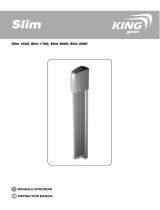 KINGgates Slim Manuale del proprietario


