
Peristaltic metering pump
DULCO flex Control, DFXa
Operating instructions
EN
Original operating instructions (2006/42/EC)Part no. 981953 BA DX 027 07/19 EN
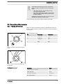
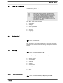
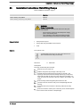
Please carefully read these operating instructions before use. · Do not discard.
The operator shall be liable for any damage caused by installation or operating errors.
The latest version of the operating instructions are available on our homepage.

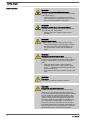
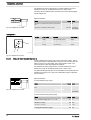
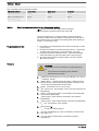
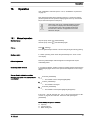
Read the following supplementary information in its entirety! Should you
already know this information, you will benefit more from referring to the
operating instructions.
The following are highlighted separately in the document:
n Enumerated lists
Instructions
ð
Outcome of the instructions
Ä ‘State the identity code and serial number’ on page 2
: Links to points
in this chapter
- refer to ... : References to points in this document or another document
[Keys]
‘Menu level 1
è
Menu level 2
è
Menu level ...’
: Menu paths
‘Software interface text’
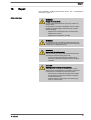
Information
This provides important information relating to the cor‐
rect operation of the unit or is intended to make your
work easier.
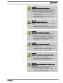
Safety Information
Safety information is identified by pictograms - see "Safety Chapter".
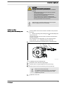
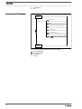
Please state the identity code and serial number, which you can find on
the nameplate or in the menu under
‘Setting / Menu
è
Information’
when
you contact us or order spare parts. This enables the unit type and mate‐
rial versions to be clearly identified.
Supplementary information
Fig. 1: Please read!
State the identity code and serial number
Supplemental directives
2

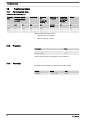
Table of contents
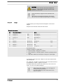
1
Identity code.................................................................................... 5
2 About this pump............................................................................... 8
3 Safety chapter................................................................................. 9
4 Storage, transport and unpacking................................................. 14
5 Overview of equipment and control elements............................... 15
5.1 Overview of equipment......................................................... 15
5.2 Control elements................................................................... 16
5.2.1 Control elements................................................................ 16
5.2.2 Key functions...................................................................... 18
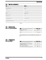
6 Functional description.................................................................... 20
6.1 Device................................................................................... 20
6.2 Capacity................................................................................ 20
6.3 Operating modes................................................................... 20
6.4 Functions............................................................................... 20
6.5 Relay (options)...................................................................... 21
6.6 LED displays......................................................................... 21
6.7 Hierarchy of operating modes, functions and fault sta‐
tuses......................................................................................
22
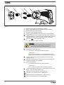
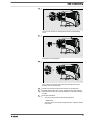
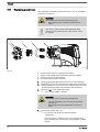
7 Assembly....................................................................................... 23
7.1 Changing dosing head alignment.......................................... 23
8 Installation, hydraulic..................................................................... 26
9 Installation, electrical..................................................................... 29
9.1 Supply voltage connector - mains voltage............................ 30
9.2 Description of the terminals................................................... 31
9.2.1 "Config I/O” terminal........................................................... 31
9.2.2 "External control" terminal.................................................. 32
9.2.3 "Level switch" terminal....................................................... 33
9.2.4 "Metering monitor" terminal................................................ 34
9.2.5 "Hose rupture indicator" terminal....................................... 34
9.2.6 Relay.................................................................................. 35
10 Basic set-up principles................................................................... 39
10.1 Basic principles for setting up the control............................ 39
10.2 Checking adjustable variables............................................ 41
10.3 Changing to Setting mode................................................... 41
11 Initial commissioning..................................................................... 42
12 Set up /
‘Menu’
.............................................................................. 45
12.1
‘Information’
....................................................................... 45
12.2
‘Settings’
............................................................................ 45
12.2.1
‘Operating mode’
............................................................. 45
12.2.2 Dosing direction............................................................... 49
12.2.3 Concentration................................................................... 49
12.2.4 Calibrate........................................................................... 54
12.2.5 System............................................................................. 56
12.2.6 Inputs/outputs................................................................... 57
12.2.7
‘Priming time’
.................................................................. 59
12.2.8
‘Set time’
......................................................................... 59
12.2.9
‘Date’
............................................................................... 60
12.3
‘Hose replacement’
............................................................ 60
12.4 Timer................................................................................... 60
12.4.1 Activation / deactivation................................................... 60
12.4.2 Setting the timer............................................................... 61
12.4.3 Clear all............................................................................ 68
Table of contents
3

12.4.4 Examples......................................................................... 68
12.4.5 Timer information............................................................. 72
12.4.6 Typical pitfalls Timer functional faults............................. 72
12.4.7 Brief explanation of selected functions............................. 73
12.5
‘Service’
............................................................................. 76
12.5.1
‘Access protection’
.......................................................... 77
12.5.2
‘Password ’
...................................................................... 78
12.5.3
‘Clear counters’
............................................................... 78
12.5.4
‘Hose’
.............................................................................. 78
12.5.5
‘Error log book’
................................................................ 79
12.5.6
‘Display’
........................................................................... 80
12.5.7
‘Factory setting’
............................................................... 80
12.5.8 Spare parts kit number: XXXXXXX.................................. 80
12.6
‘Language’
......................................................................... 80
13 Operation....................................................................................... 81
13.1 Manual operation................................................................ 81
14 Maintenance.................................................................................. 83
15
Repair............................................................................................ 85
15.1 Replacing pump hose......................................................... 86
15.2 Cleaning hose rupture indicator (option)............................. 88
16 Troubleshooting............................................................................. 89
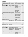
16.1 Faults without a fault message............................................ 89
16.2 Faults with error message................................................... 89
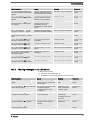
16.2.1 Fault messages on the LCD screen................................. 89
16.2.2 Warning messages on the LCD screen........................... 91
16.2.3 All other faults.................................................................. 92
16.3 Log book............................................................................. 92
16.3.1 Fault messages in the log book....................................... 92
16.3.2 Warning messages in the log book.................................. 93
16.3.3 Event messages in the log book...................................... 94
16.3.4 Log book entry - detailed view......................................... 94
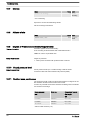
17 Decommissioning and disposal..................................................... 96
18 Technical data............................................................................... 98
18.1 Performance data................................................................ 98
18.2 Precision............................................................................. 98
18.3 Viscosity.............................................................................. 98
18.4 Material specifications......................................................... 99
18.5 Electrical data...................................................................... 99
18.6 Temperatures...................................................................... 99
18.7 Climate.............................................................................. 100
18.8 Altitude of site ................................................................... 100
18.9 Degree of Protection and Safety Requirements................ 100
18.10 Sound pressure level...................................................... 100
18.11 Suction lance, continuous............................................... 100
19 Dimensional drawings................................................................. 102
20
Declaration of Conformity for Machinery..................................... 103
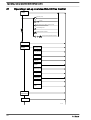
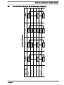
21 Operating / set-up overview DULCO flex Control........................ 104
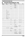
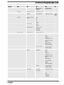
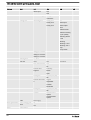
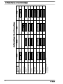
22 DULCO flex Control operating menu, overall.............................. 106
23 Continuous displays and secondary displays.............................. 111
24 Installation instructions: Retrofitting Relays ................................ 113
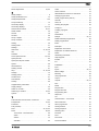
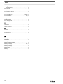
25 Index............................................................................................ 115
Table of contents
4

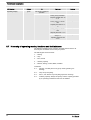
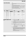
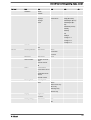
1 Identity code
Product identification
This identity code serves to identify the product.
Use the identity code from the Product Catalogue for
orders.
Product range DULCO flex Control
DFXa
Regional design
EU Europe
US USA
CN China
Pump type
0730 7 bar, 30 l/h
0530 5 bar, 30 l/h
Hose material / connections / O-rings
SP TPV / PVDF / PTFE
VP PUR / PVDF / PTFE
Seal material
F FDA-compliant (PTFE)
T PTFE
Dosing head orientation (orientation of hydraulic connectors - viewed from behind)
R right
L left
O top
U bottom
Hydraulic connector
0 Standard connector (12x9)
2 8x5 connector
5 12x6 connector, discharge side
7 without connector kit
8 9x5 connector
E DN10 connector, with nozzle
Hose rupture indicator
0 none
1 Optical hose rupture indicator
Design
0 Housing RAL5003 / Hood RAL2003
2 Housing RAL5003 / Hood RAL3001
M modified
Identity code
5

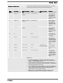
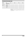
Product range DULCO flex Control
Logo
0 with ProMinent logo
2 without ProMinent logo
Version of power unit
U 100-240 V
Cable and plug
A 2 m, Europe
B 2 m, Switzerland
C 2 m, Australia
D 2 m, USA / 115 V
1 2 m, open end
.. ...
Relay function
0 no relay -
1 1 x changeover contact
230 V AC – 6 A
Fault indicating relay (N/C)
4 1 x N/O 24 V DC – 1 A
1 x N/O 24 V DC – 100
mA
as 1 + pacing relay
C 1 x N/O 24 V DC – 100
mA, and 1 x 4-20 mA
output
As 1 + 4-20 mA output
.. ...
Accessories
0 no accessories
1 with 1/2” injection valve and foot valve
2 as 0 + measuring cup
3 as 1 + measuring cup
Control version
0 Manual + external contact with pulse control
3 Manual + external contact with pulse control +
analog 0/4-20mA
C As 3 + CANopen
E As 3 + PROFINET
R
As 3 + PROFIBUS
®
M12 plug
M As 3 + Modbus RTU
Communication
0 none
W with Wi-Fi
B Bluetooth
Language
DE German
Identity code
6

Product range DULCO flex Control
EN English
ES Spanish
FR French
... ...
Identity code
7

2 About this pump
Pumps in the DULCO flex Control product range are microprocessor-con‐
trolled peristaltic metering pumps with the following characteristics:
n simple adjustment of the capacity directly in l/h or in gph
n flow reversal possible
n simpler hose replacement supported by software
n only the medium comes into contact with the hose
n CIP-compatible - when pump is running
n direct input of the required final concentration with volume-propor‐
tional metering tasks in concentration mode
n external control via potential-free contacts with pulse step-up and
step-down
n external control via 0/4-20 mA standard signal, scalable
n integrated 1-week/1-month timer
n connection to process control systems via a BUS interface, such as
PROFINET, Modbus RTU or CAN bus
n DULCOnneX-compatible
About this pump
About this pump
8

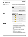
3 Safety chapter
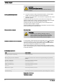
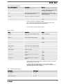
The following signal words are used in these operating instructions to
denote different severities of danger:
Signal word Meaning
WARNING Denotes a possibly dangerous sit‐
uation. If this is disregarded, you
are in a life-threatening situation
and this can result in serious inju‐
ries.
CAUTION Denotes a possibly dangerous sit‐
uation. If this is disregarded, it
could result in slight or minor inju‐
ries or material damage.
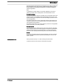
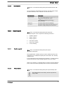
The following warning signs are used in these operating instructions to
denote different types of danger:
Warning signs Type of danger
Warning – automatic start-up.
Warning – hand injuries.
Warning – high-voltage.
Warning – danger zone.
n Only use the pump to meter liquid feed chemicals.
n The pump may only be started up after it has been correctly installed
and started up in accordance with the technical data and specifica‐
tions contained in the operating instructions.
n Observe the general limitations with regard to viscosity limits, chem‐
ical resistance and density - see also ProMinent resistance list in the
Product Catalogue or at www.prominent.com! Use the "Chemical
Resistance List DFXa" available at www.prominent.com for the pump
hose.
n All other uses or modifications are prohibited.
n The pump is not intended for the metering of gaseous media and
solids.
n The pump is not intended to meter flammable media.
n The pump is not intended for the metering of explosive media.
n The pump is not intended for use outdoors without appropriate protec‐
tive measures.
n The pump should only be operated by trained and authorised per‐
sonnel - see the following "Qualifications" table.
n You have a duty to observe the information contained in the operating
instructions during the different phases of the device's service life.
Identification of safety notes
Warning signs denoting different types of
danger
Intended use
Safety chapter
9

WARNING!
Warning about personal and material damage
The pump can start to pump, as soon as it is connected
to the mains voltage.
– Install an emergency cut-off switch in the pump
power supply line or integrate the pump in the emer‐
gency cut-off management of the system.
WARNING!
Warning of personal injury and material damage
The pump can start pumping as soon as it has cooled
down after the error
‘temperature’
.
– Take this into account with the pump and your
installation.
WARNING!
Danger of electric shock
A mains voltage may exist inside the pump housing.
– If the pump housing has been damaged, you must
disconnect it from the mains immediately. It may
only be returned to service after an authorised
repair.
WARNING!
Warning of hazardous feed chemical
Should a dangerous feed chemical be used: it may
escape from the hydraulic components when working on
the pump, material failure or incorrect handling of the
pump.
– Take appropriate protective measures before
working on the pump (e.g. safety glasses, safety
gloves, ...). Adhere to the material safety data sheet
for the feed chemical.
–
Drain and flush the liquid end before working on the
pump.
WARNING!
Fire danger
The pumping of flammable media is prohibited.
WARNING!
Danger from hazardous substances!
Possible consequence: Fatal or very serious injuries.
Please ensure when handling hazardous substances
that you have read the latest safety data sheets provided
by the manufacture of the hazardous substance. The
actions required are described in the safety data sheet.
Check the safety data sheet regularly and replace, if
necessary, as the hazard potential of a substance can
be re-evaluated at any time based on new findings.
The system operator is responsible for ensuring that
these safety data sheets are available and that they are
kept up to date, as well as for producing an associated
hazard assessment for the workstations affected.
Safety information
Safety chapter
10

CAUTION!
Warning of feed chemical spraying around
Feed chemical can spray out of the hydraulic compo‐
nents if they are manipulated or opened due to pressure
in the liquid end and adjacent parts of the system.
– Disconnect the pump from the mains power supply
and ensure that it cannot be switched on again by
unauthorised persons.
–
Depressurise the system before commencing any
work on hydraulic parts.
CAUTION!
Warning of body parts being drawn in
The rotor running in the liquid end may draw in and trap
body parts.
– Do not reach into the running rotor.
–
Only take off bearing cover once prompted to do so
by the operating instructions or operating software.
CAUTION!
Warning of feed chemical spraying around
An unsuitable feed chemical can damage the parts of
the pump that come into contact with the chemical.
– Take into account the resistance of the wetted mate‐
rials and the ProMinent Resistance List when
selecting the feed chemical - see the ProMinent
Product Catalogue or visit ProMinent.
CAUTION!
Warning of feed chemical spraying around
An unsuitable feed chemical may cause premature wear
to the pump hose.
– Observe the pump hose's resistance and "Chemical
Resistance List DFXa" available at www.promi‐
nent.com when selecting the feed chemical.
CAUTION!
Danger of injury to personnel and material damage
The use of untested third party components can result in
injury to personnel and material damage.
– Only fit parts to metering pumps that have been
tested and recommended by ProMinent.
CAUTION!
Danger from incorrectly operated or inadequately main‐
tained pumps
Danger can arise from a poorly accessible pump due to
incorrect operation and poor maintenance.
– Ensure that the pump is accessible at all times.
–
Adhere to the maintenance intervals.
Safety chapter
11

CAUTION!
Warning against illegal operation
Observe the regulations that apply where the device is
installed.
n Cover for the slot for relays and optional modules - see the chapter
entitled "Overview of Equipment and Control Elements"
n Bearing cover for liquid end - see "Overview of equipment and control
elements” chapter
Customers should only remove the cover for the slot for relays and
optional modules and/or a relay or optional module in line with the supple‐
mentary instructions for the relays and optional modules.
Customers should only remove the bearing cover for the liquid end in
accordance with the "Repair" chapter.
Only the ProMinent service department is authorised to open the housing
and hood (housing the control elements).
Adhesive labels
WARNING!
– A warning sign indicating "Warning of injury to
hands" is stuck on the pump and warns of rotating
parts and the risk of being drawn into the liquid end.
–
Ensure that the label is always fitted and legible.
In an emergency, either disconnect the mains plug, press
[Start/Stop]
or press the Emergency Stop switch installed on the customer's side or
disconnect the pump from the mains/power supply in line with the Emer‐
gency Stop management guidelines for your system.
If feed chemical escapes, also ensure that the pump's hydraulic environ‐
ment is at atmospheric pressure. Adhere to the material safety data sheet
for the feed chemical.
Task Qualification
Storage, transport, unpacking Instructed person
Assembly Technical personnel, service
Planning the hydraulic installation Technical personnel who have a thorough knowledge of peristaltic
pumps
Hydraulic installation Technical personnel, service
Electrical installation Electrical technician
Initial commissioning Technical personnel, service
Operation Instructed person
Maintenance, repair Technical personnel, service
Decommissioning, disposal Technical personnel, service
Troubleshooting Technical personnel, electrical technician, instructed person, service
Explanation of the table:
Technical personnel
Isolating protective equipment
Other protective equipment
Information in the event of an emergency
Qualification of personnel
Safety chapter
12

Technical personnel are deemed to be people who are able to assess the
tasks assigned to them and recognise possible dangers based on their
technical training, knowledge and experience, as well as knowledge of
pertinent regulations.
Note:
A qualification of equal validity to a technical qualification can also be
gained by several years of employment in the relevant field of work.
Electrical technician
An electrical technician is able to complete work on electrical systems and
recognise and avoid possible dangers independently based on his or her
technical training and experience as well as knowledge of pertinent stand‐
ards and regulations.
The electrical technician must be specifically trained for the working envi‐
ronment in which he or she is employed and be conversant with the rele‐
vant standards and regulations.
The electrical technician must comply with the provisions of the applicable
statutory directives on accident prevention.
Instructed person
An instructed person is deemed to be a person who has been instructed
and, if required, trained in the tasks assigned to him/her and possible dan‐
gers that could result from improper behaviour, as well as having been
instructed in the required protective equipment and protective measures.
Service
The service department refers to service technicians, who have received
proven training and have been authorised by ProMinent to work on the
device / system.
Sound pressure level LpA < 70 dB according to EN ISO 20361
at maximum feed rate and maximum back pressure (water)
Sound pressure level
Safety chapter
13

4 Storage, transport and unpacking
User qualification: Instructed person - see
Ä ‘Qualification of personnel’
on page 12
WARNING!
Only return metering pumps for repair in a cleaned state
and with a flushed liquid end - refer to "Decommis‐
sioning!
Only return metering pumps with a completed Decon‐
tamination Declaration form. The Decontamination Dec‐
laration constitutes an integral part of an inspection /
repair order. A unit can only be inspected or repaired
when a Declaration of Decontamination Form is sub‐
mitted that has been completed correctly and in full by
an authorised and qualified person on behalf of the
pump operator.
The "Decontamination Declaration Form" can be found
on our homepage.
CAUTION!
Danger of material damage
The device can be damaged by incorrect or improper
storage or transportation!
– The unit should only be stored or transported in a
well packaged state - preferably in its original pack‐
aging.
–
The packaged unit should also only be stored or
transported in accordance with the stipulated
storage conditions.
– The packaged unit should be protected from mois‐
ture and the ingress of chemicals.
Ambient conditions - see "Technical Data" chapter.
Storage period of pump hose non-condensing, max.: 2 years
Compare the delivery note with the scope of delivery:
n Metering pump with mains cable
n Pump hose
n Rotor half
n Connector kit for hose/pipe connection (option)
n Product-specific operating instructions with EU Declaration of Con‐
formity
n Optional accessories
Safety information
Ambient conditions
Storage period, max.
Scope of delivery
Storage, transport and unpacking
14

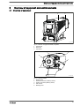
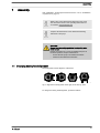
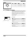
5 Overview of equipment and control elements
5.1
Overview of equipment
1
P_G_0103_SW
2 3
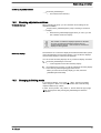
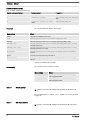
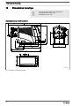
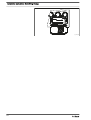
Fig. 2: Overview of equipment DFXa, complete
1 Control unit
2 Drive unit
3 Liquid end
P DX 0177 SW
1
2
3
4
5
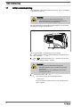
Fig. 3: Liquid end DFXa
1 Dosing head
2 Pressure connector (delivery status)
3 Suction connector (delivery status)
4 Star screws
5 Bearing cover
Overview of equipment and control elements
15

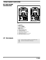
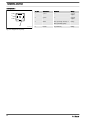
5.2 Control elements
a)
b)
P_G_0105_SW
12 14
15
13
10
11
3
1
5
4
2
9
8
7
6
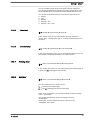
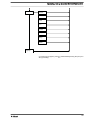
Fig. 4
1 LCD screen
2
[Menu]
key
3
Clickwheel
4
[Priming]
key
5
[STOP/START]
key
6
[Back]
key
7 Fault indicator (red)
8 Warning indicator (yellow)
9 Operating indicator (green)
10 "Config I/O” terminal
11 "Hose rupture indicator" terminal
12 "External control" terminal
13 "Metering monitor" terminal (no function)
14 "Level switch" terminal
15 Slot for relays and optional modules
5.2.1 Control elements
Use this overview to familiarise yourself with the keys
and other control elements on the pump!
Control elements, overview
Overview of equipment and control elements
16

10.0
10.0 mA
ANALOG
4..20mA
l/h
B1150
1
3
2
AUX
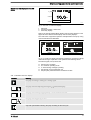
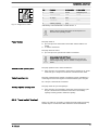
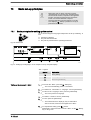
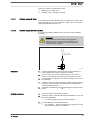
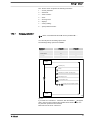
Fig. 5: Structure of continuous display
1 Status bar
2 Continuous display, central area
3 Secondary display
Refer to the chapter entitled "Main displays and secondary displays" in the
Appendix for the different main displays and secondary displays.
The LCD screen supports the operation and adjustment of the pump using
various information and identifiers:
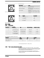
30.0
Level
MANUAL
l/h
Service: 600 h
MANUAL
Level error!
B1151
a)
b)
Level
602371
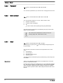
Fig. 6: a) Continuous display with warning message; b) Continuous display
with fault message. Explanation of the symbols in the following tables.
The above Figure, Part a) shows that:
n the pump is in operation
n is in
‘Manual’
operating mode
n a
‘level’
warning message is pending
n the capacity of 30.0 l/h has been set
n the pump has performed 602371 revolutions to date
Tab. 1: Identifiers and error displays:
Identifier Meaning
The pump is working or waiting for a starting signal.
The pump was manually stopped using the
[STOP/START]
key.
The pump was remotely stopped (Pause) - via the "External" terminal.
The pump was stopped by an error.
Only with cyclical batch metering: the pump is waiting for the next cycle.
Identifier and fault displays on the LCD
screen
Overview of equipment and control elements
17

Identifier Meaning
Only with
‘Access protection’
: the pump software is locked.
‘AUX’
The pump is currently pumping at auxiliary capacity.
‘memory’
Only in
‘CONTACT’
and
‘BATCH’
operating modes:
the auxiliary function "Memory" has been set.
The pump is in
‘ANALOG’
operating mode.
The
‘Curve
è
linear’
type of processing is set.
The pump is in
‘ANALOG’
operating mode.
The
‘Curve
è
Upper side band’
type of processing is set.
A hose rupture indicator is connected.
The pump is in the
‘Menu’
(Set up).
Further explanations can be found in the "Trouble‐
shooting" chapter.
The pump only shows the metering volume and the
capacity in the calibrated state in l or l/h or in gal or gal/h
(US gallons).
5.2.2 Key functions
Key Application In the continuous displays In the menu
[Back]
press - Go back to the previous menu
item (or a continuous display) -
without saving
[STOP/
START]
press Stop pump, Stop pump,
Start pump Start pump
[Menu]
press Go to the menu Go back to a continuous display
[Priming]
press Priming * Priming *
[Clickwheel]
press Start batch (only in
‘Batch’
operating
mode),
Acknowledge errors
Go to next menu item (or a contin‐
uous display)
Confirm entry and save
[Clickwheel]
turn Switch between the continuous dis‐
plays
Change figure or change selection
Overview of equipment and control elements
18

* When priming the pump does not run at maximum
number of revolutions.
If
[Priming] is pressed in ‘Stop’ state, then [Priming]
has top priority as long as the button is pressed.
Refer to the "Set-up basics" chapter for how to adjust fig‐
ures
Overview of equipment and control elements
19

6 Functional description
6.1
Device
An electric motor drives a rotor. Rollers are fitted to the ends of the rotors,
which press the pump hose against the inner curvature of the dosing
head. The peristaltic pump operates by the rollers driving the feed chem‐
ical through the pump hose. The feed chemical is primed by the pump
hose automatically returning to its initial position.
6.2 Capacity
The capacity that has been set regulates the pump itself.
6.3 Operating modes
Operating modes are selected via the "Operating modes" menu.
Refer to the "Hierarchy of Operating Modes, Functions and Fault Statuses"
for the order of the various operating modes, functions and fault statuses.
‘Manual’
operating mode permits you to operate the pump manually.
This operating mode provides the option of controlling the pump externally
by means of potential-free contacts (e.g. by means of a contact water
meter). “Pulse Control” can be used to preselect the metering volume in
the
‘Settings’
menu.
This operating mode provides the option of working with large metering
volumes. Metering can be triggered either by pressing the
[Clickwheel]
or
by a pulse received via the "External control" terminal via a contact or a
semiconductor switching element. It is possible to pre-select a metering
volume (batch) and a metering time using the
[Clickwheel]
in the
‘Settings’
menu.
The capacity is controlled using an analogue current signal via the
"External control" terminal. Processing of the current signal can be prese‐
lected using the control unit.
6.4 Functions
Refer to the "Hierarchy of Operating Modes, Functions and Fault Statuses"
for the order of the various operating modes, functions and fault statuses.
The following functions can be selected using the
‘Settings’
menu:
"Manual" operating mode
"Contact" operating mode
"Batch" operating mode
"Analog" operating mode
Functional description
20
La pagina sta caricando ...
La pagina sta caricando ...
La pagina sta caricando ...
La pagina sta caricando ...
La pagina sta caricando ...
La pagina sta caricando ...
La pagina sta caricando ...
La pagina sta caricando ...
La pagina sta caricando ...
La pagina sta caricando ...
La pagina sta caricando ...
La pagina sta caricando ...
La pagina sta caricando ...
La pagina sta caricando ...
La pagina sta caricando ...
La pagina sta caricando ...
La pagina sta caricando ...
La pagina sta caricando ...
La pagina sta caricando ...
La pagina sta caricando ...
La pagina sta caricando ...
La pagina sta caricando ...
La pagina sta caricando ...
La pagina sta caricando ...
La pagina sta caricando ...
La pagina sta caricando ...
La pagina sta caricando ...
La pagina sta caricando ...
La pagina sta caricando ...
La pagina sta caricando ...
La pagina sta caricando ...
La pagina sta caricando ...
La pagina sta caricando ...
La pagina sta caricando ...
La pagina sta caricando ...
La pagina sta caricando ...
La pagina sta caricando ...
La pagina sta caricando ...
La pagina sta caricando ...
La pagina sta caricando ...
La pagina sta caricando ...
La pagina sta caricando ...
La pagina sta caricando ...
La pagina sta caricando ...
La pagina sta caricando ...
La pagina sta caricando ...
La pagina sta caricando ...
La pagina sta caricando ...
La pagina sta caricando ...
La pagina sta caricando ...
La pagina sta caricando ...
La pagina sta caricando ...
La pagina sta caricando ...
La pagina sta caricando ...
La pagina sta caricando ...
La pagina sta caricando ...
La pagina sta caricando ...
La pagina sta caricando ...
La pagina sta caricando ...
La pagina sta caricando ...
La pagina sta caricando ...
La pagina sta caricando ...
La pagina sta caricando ...
La pagina sta caricando ...
La pagina sta caricando ...
La pagina sta caricando ...
La pagina sta caricando ...
La pagina sta caricando ...
La pagina sta caricando ...
La pagina sta caricando ...
La pagina sta caricando ...
La pagina sta caricando ...
La pagina sta caricando ...
La pagina sta caricando ...
La pagina sta caricando ...
La pagina sta caricando ...
La pagina sta caricando ...
La pagina sta caricando ...
La pagina sta caricando ...
La pagina sta caricando ...
La pagina sta caricando ...
La pagina sta caricando ...
La pagina sta caricando ...
La pagina sta caricando ...
La pagina sta caricando ...
La pagina sta caricando ...
La pagina sta caricando ...
La pagina sta caricando ...
La pagina sta caricando ...
La pagina sta caricando ...
La pagina sta caricando ...
La pagina sta caricando ...
La pagina sta caricando ...
La pagina sta caricando ...
La pagina sta caricando ...
La pagina sta caricando ...
La pagina sta caricando ...
La pagina sta caricando ...
La pagina sta caricando ...
La pagina sta caricando ...
-
 1
1
-
 2
2
-
 3
3
-
 4
4
-
 5
5
-
 6
6
-
 7
7
-
 8
8
-
 9
9
-
 10
10
-
 11
11
-
 12
12
-
 13
13
-
 14
14
-
 15
15
-
 16
16
-
 17
17
-
 18
18
-
 19
19
-
 20
20
-
 21
21
-
 22
22
-
 23
23
-
 24
24
-
 25
25
-
 26
26
-
 27
27
-
 28
28
-
 29
29
-
 30
30
-
 31
31
-
 32
32
-
 33
33
-
 34
34
-
 35
35
-
 36
36
-
 37
37
-
 38
38
-
 39
39
-
 40
40
-
 41
41
-
 42
42
-
 43
43
-
 44
44
-
 45
45
-
 46
46
-
 47
47
-
 48
48
-
 49
49
-
 50
50
-
 51
51
-
 52
52
-
 53
53
-
 54
54
-
 55
55
-
 56
56
-
 57
57
-
 58
58
-
 59
59
-
 60
60
-
 61
61
-
 62
62
-
 63
63
-
 64
64
-
 65
65
-
 66
66
-
 67
67
-
 68
68
-
 69
69
-
 70
70
-
 71
71
-
 72
72
-
 73
73
-
 74
74
-
 75
75
-
 76
76
-
 77
77
-
 78
78
-
 79
79
-
 80
80
-
 81
81
-
 82
82
-
 83
83
-
 84
84
-
 85
85
-
 86
86
-
 87
87
-
 88
88
-
 89
89
-
 90
90
-
 91
91
-
 92
92
-
 93
93
-
 94
94
-
 95
95
-
 96
96
-
 97
97
-
 98
98
-
 99
99
-
 100
100
-
 101
101
-
 102
102
-
 103
103
-
 104
104
-
 105
105
-
 106
106
-
 107
107
-
 108
108
-
 109
109
-
 110
110
-
 111
111
-
 112
112
-
 113
113
-
 114
114
-
 115
115
-
 116
116
-
 117
117
-
 118
118
-
 119
119
-
 120
120


ProMinent DFXa Operating Instructions Manual
- Tipo
- Operating Instructions Manual
- Questo manuale è adatto anche per
in altre lingue
- English: ProMinent DFXa
Documenti correlati
-
ProMinent DULCO flex Control-DFYa Operating Instructions Manual
-
-
-
-
-
Altri documenti
-
Grundfos DME 375 Installation And Operating Instructions Manual
-
Grundfos DTS Installation And Operating Instructions Manual
-
Dynisco SPXD Manuale utente
-
CTX BOMBAPRO PH-RX Operating
-
Regal 42 Fly-Grande Coupe Manuale del proprietario
-
-
-
Hobart Protronic XL PREMAX FTPi Series Installation And Operation Instructions Manual
-
-
Micro Motion FMS-3 Flow Monitoring System LED Manuale del proprietario