ProMinent 1081318 Assembly And Operating Instructions Manual
- Tipo
- Assembly And Operating Instructions Manual

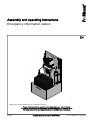
Emergency chlorination station
Assembly and operating instructions
A2487
Target group: At least trained users, if not otherwise required.
EN
Original operating instructions (2006/42/EC)981219 Version: BA DST 014 07/20 EN
Please carefully read these operating instructions before use. · Do not discard.
The operator shall be liable for any damage caused by installation or operating errors.
The latest version of the operating instructions are available on our homepage.

In order to make it easier to read, this document uses the male
form in grammatical structures but with an implied neutral sense.
The document is always aimed equally at women, men and
gender-neutral persons. We kindly ask readers for their under‐
standing in this simplification of the text.
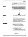
Please read the supplementary information in its entirety.
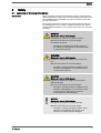
Information
This provides important information relating to the
correct operation of the unit or is intended to make
your work easier.
Warning information
Warning information includes detailed descriptions of the haz‐
ardous situation, see
Ä Chapter 2.1 ‘Labelling of Warning Informa‐
tion’ on page 5
.
The following symbols are used to highlight instructions, links, lists,
results and other elements in this document:
Tab. 1: More symbols
Symbol Description
Action, step by step.
⇨ Outcome of an action.
Links to elements or sections of these instructions or other applicable documents.
n
List without set order.
[Button]
Display element (e.g. indicators).
Operating element (e.g. button, switch).
‘Display/GUI’
Screen elements (e.g. buttons, assignment of function keys).
CODE
Presentation of software elements and/or texts.
General non-discriminatory approach
Supplementary information
Supplemental directives
2

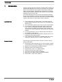
Table of contents
1 Introduction........................................................................... 4
2 Safety.................................................................................... 5
2.1 Labelling of Warning Information.................................. 5
2.2 General safety information............................................ 6
2.3 Intended use................................................................. 6
2.4 User qualification.......................................................... 7
3 Storage and transport........................................................... 8
3.1 Storage......................................................................... 8
3.2 Packaging material....................................................... 8
4 Assembly and installation..................................................... 9
4.1 Installation, hydraulic.................................................... 9
4.2 Installation, electrical.................................................... 9
5 Start up............................................................................... 10
6 Operation............................................................................ 11
6.1 Setting up the metering pump using the example of
sodium-calcium hypochlorite in potable water............ 11
6.1.1 Manual control with a constant supply of potable
water........................................................................ 11
6.1.2 Control using the contact water meter..................... 14
6.1.3 Control using an inductive flow meter IDM.............. 16
7 Maintenance and repair...................................................... 19
8 Decommissioning................................................................ 21
9 Disposal of used parts........................................................ 22
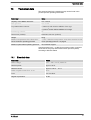
10 Technical data..................................................................... 23
10.1 Electrical data........................................................... 23
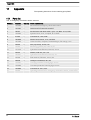
11 Appendix............................................................................. 24
11.1 Parts list.................................................................... 24
11.2 EC Declaration of Conformity for Machinery............ 25
12 Index................................................................................... 26
Table of contents
3

1 Introduction
These operating instructions describe a mobile metering station for
potable water disinfection for short-term, temporary use. The disin‐
fectant can be metered in situ using the fully ready mounted and
ready connected station. All disinfectants permitted in accordance
with the Drinking Water Ordinance 2001 and the List of Permitted
Substances (§11) can be used.
The mobile metering station can be used to eliminate contamina‐
tion by micro-organisms, as well as for prescribed flushing and dis‐
infection when commissioning newly laid pipes or recently installed
systems, after repairs or after longer periods of idleness.
n For the disinfection of potable water in accordance with the
Drinking Water Ordinance 2001 and the List of Permitted Sub‐
stances (§11).
n As an immediate measure in the event of acute contamination.
n For operators of widely ramified water supply systems and
lines, such as municipalities, hospitals, elderly care homes,
sports and leisure facilities and barracks, and in industry and
commerce for “shock” disinfection should there be a legionella
incident.
n For aid organisations to set up mobile potable water disinfec‐
tion stations in crisis regions.
n For plumbing businesses for disinfection purposes when com‐
missioning water supply systems.
n For the flushing and disinfection of potable water and process
water lines at events, such as concerts, village fairs etc.
The emergency chlorination station 1081318 consists of the fol‐
lowing components:
n Support frame with collecting pan for a 35 kg canister (canister
is not included in the scope of delivery of the metering station).
n Bracket for the metering pump (PE-HD natural).
n Winding bracket for the metering hose.
n Injection lance, short, 1/2”, PCB (1028363)
n Tubular housing for the injection lance.
n 10 m hose, PVC soft, 12x6 mm (1004539).
n Metering pump, GMXa 1604PVT79000UA10300DE
n Suction lance , PCB, 12x9, (790371)
Application/Use
Scope of delivery
Introduction
4

2 Safety
2.1 Labelling of Warning Information
These operating instructions provide information on the technical
data and functions of the product. These operating instructions pro‐
vide detailed warning information and are provided as clear step-
by-step instructions.
The warning information and notes are categorised according to
the following scheme. A number of different symbols are used to
denote different situations. The symbols shown here serve only as
examples.
DANGER!
Nature and source of the danger
Consequence: Fatal or very serious injuries.
Measure to be taken to avoid this danger.
Description of hazard
– Denotes an immediate threatening danger. If
the situation is disregarded, it will result in fatal
or very serious injuries.
WARNING!
Nature and source of the danger
Possible consequence: Fatal or very serious inju‐
ries.
Measure to be taken to avoid this danger.
– Denotes a possibly hazardous situation. If the
situation is disregarded, it could result in fatal
or very serious injuries.
CAUTION!
Nature and source of the danger
Possible consequence: Slight or minor injuries.
Material damage.
Measure to be taken to avoid this danger.
– Denotes a possibly hazardous situation. If the
situation is disregarded, it could result in slight
or minor injuries. May also be used as a
warning about material damage.
NOTICE!
Nature and source of the danger
Damage to the product or its surroundings.
Measure to be taken to avoid this danger.
– Denotes a possibly damaging situation. If the
situation is disregarded, the product or an
object in its vicinity could be damaged.
Introduction
Safety
5

Type of information
Hints on use and additional information.
Source of the information. Additional measures.
–
Denotes hints on use and other useful informa‐
tion. It does not indicate a hazardous or dam‐
aging situation.
2.2 General safety information
Ensure that there can be no unauthorised access to the unit.
Make sure that only trained personnel fit, install, maintain and
operate the unit.
Please also observe the operating instructions for the metering
pump and any other units which may be fitted!
Only use the sensor in bypass fittings, which ensure the correct
flow parameters (l/h, see Technical data).
Pay attention to the resistance of the wetted materials of all units,
referring to the ProMinent Resistance List in the product catalogue
or at
www.prominent.com
.
Check the resistance of any pre-mixed chemicals with the chemical
manufacturer before using.
WARNING!
Danger from hazardous substances!
Possible consequence: Fatal or very serious inju‐
ries.
Please ensure when handling hazardous sub‐
stances that you have read the latest safety data
sheets provided by the manufacture of the haz‐
ardous substance. The actions required are
described in the safety data sheet. Check the
safety data sheet regularly and replace, if neces‐
sary, as the hazard potential of a substance can be
re-evaluated at any time based on new findings.
The system operator is responsible for ensuring
that these safety data sheets are available and that
they are kept up to date, as well as for producing
an associated hazard assessment for the worksta‐
tions affected.
2.3 Intended use
The metering system is only designed for metering liquid feed
chemicals in hydraulic systems.
All other uses or modifications of the system are only permitted
after consultation with and with the approval of the manufacturer.
The metering system is not intended for the metering of gaseous or
solid media, or other seriously gaseous media.
Unauthorised access
Operating instructions for the other
components
ProMinent Resistance List
Safety
6

The metering system is not intended for metering slightly flam‐
mable or explosive media.
The metering system is not suitable for use in premises at risk of
explosion.
Do not operate the system under conditions other than those
described in the technical data.
2.4 User qualification
WARNING!
Danger of injury with inadequately qualified per‐
sonnel
The operator of the system / equipment is respon‐
sible for ensuring that the qualifications are ful‐
filled.
If inadequately qualified personnel work on the unit
or loiter in the hazard zone of the unit, this could
result in dangers that could cause serious injuries
and material damage.
– All work on the unit should therefore only be
conducted by qualified personnel.
– Unqualified personnel should be kept away
from the hazard zone.
The pertinent accident prevention regulations, as
well as all other generally acknowledged safety
regulations, must be adhered to.
Training Definition
Instructed personnel An instructed person is deemed to be a person who has been instructed and,
if required, trained in the tasks assigned to him and possible dangers that
could result from improper behaviour, as well as having been instructed in the
required protective equipment and protective measures.
Trained user A trained user is a person who fulfils the requirements made of an instructed
person and who has also received additional training specific to the system
from the manufacturer or another authorised distribution partner.
Trained, qualified per‐
sonnel
A trained, qualified employee is deemed to be a person who is able to assess
the tasks assigned to him and recognize possible hazards based on his
training, knowledge and experience, as well as knowledge of pertinent regula‐
tions. A trained, qualified employee must be able to perform the tasks
assigned to him independently with the assistance of drawing documentation
and parts lists. The assessment of a person's technical training can also be
based on several years of work in the relevant field.
Electrical technician An electrical technician is able to complete work on electrical systems and rec‐
ognise and avoid possible dangers independently based on his technical
training and experience as well as knowledge of pertinent standards and regu‐
lations. An electrical technician must be able to perform the tasks assigned to
him independently with the assistance of drawing documentation, parts lists,
terminal and circuit diagrams. The electrical technician must be specifically
trained for the working environment in which the electrical technician is
employed and be conversant with the relevant standards and regulations.
Service The Service department refers to service technicians, who have received
proven training and have been authorised by the manufacturer to work on the
system.
Safety
7

3 Storage and transport
User qualification: instructed user
Ä Chapter 2.4 ‘User qualifica‐
tion’ on page 7
WARNING!
Danger from hazardous substances!
Possible consequence: Fatal or very serious inju‐
ries.
Please ensure when handling hazardous sub‐
stances that you have read the latest safety data
sheets provided by the manufacture of the haz‐
ardous substance. The actions required are
described in the safety data sheet. Check the
safety data sheet regularly and replace, if neces‐
sary, as the hazard potential of a substance can be
re-evaluated at any time based on new findings.
The system operator is responsible for ensuring
that these safety data sheets are available and that
they are kept up to date, as well as for producing
an associated hazard assessment for the worksta‐
tions affected.
Store and transport the metering system free from chemicals etc.
Transport, ship and store the unit in its original packaging.
3.1 Storage
Permissible ambient temperature: +0 °C ... +50 °C.
Humidity: maximum 92 % relative air humidity, non-condensing.
Other: No dust, no direct sunlight.
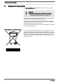
3.2 Packaging material
Dispose of packaging material in an environmentally responsible
way. All packaging components carry the corresponding recycling
code
.
Storage and transport
8

4 Assembly and installation
n User qualification, mechanical installation: trained and qualified
personnel, see
Ä Chapter 2.4 ‘User qualification’ on page 7
n User qualification, electrical installation: Electrical technician,
see
Ä Chapter 2.4 ‘User qualification’ on page 7
The metering system is not suitable for installation outdoors.
Ensure that the metering system is easily accessible for operation
and maintenance. Allow a clearance of approx. 1 metre in front of
the metering system.
Ambient conditions for operation:
n Temperature: 5 ... 40 °C
n Maximum air humidity: 92 % relative air humidity, non-con‐
densing
Tab. 2: Maximum temperature of the feed chemical at maximum operating pressure:
10 bar 7 bar 4 bar 2 bar 2 bar for 15 minutes at *
PVC-U pipework: 20 °C 35 °C 45 °C 50 °C 55 °C
*short-term (15 minutes at max. 2 bar) e.g. for sterilisation and/or flushing with hot water.
4.1 Installation, hydraulic
Note the maximum permissible pressure values, also depending
on the temperature, see
Ä Tab. 2 ‘Maximum temperature of the
feed chemical at maximum operating pressure:’ on page 9
. Other‐
wise parts of the metering system or the connected pipework
system could rupture.
Always route the discharge lines to guarantee a tension-free
mechanical connection.
4.2 Installation, electrical
The pump is equipped with a standard European plug and can be
plugged into standard electrical sockets. Sockets are ready
mounted on the bracket depending on the design of the metering
station.
Installation site
Assembly and installation
9

5 Start up
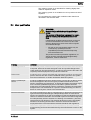
WARNING!
Danger from hazardous substances!
Possible consequence: Fatal or very serious inju‐
ries.
Please ensure when handling hazardous sub‐
stances that you have read the latest safety data
sheets provided by the manufacture of the haz‐
ardous substance. The actions required are
described in the safety data sheet. Check the
safety data sheet regularly and replace, if neces‐
sary, as the hazard potential of a substance can be
re-evaluated at any time based on new findings.
The system operator is responsible for ensuring
that these safety data sheets are available and that
they are kept up to date, as well as for producing
an associated hazard assessment for the worksta‐
tions affected.
Maximum permissible operating pressure: see
Ä Tab. 2 ‘Maximum
temperature of the feed chemical at maximum operating pressure:’
on page 9
1. Wear appropriate protective equipment for commissioning,
maintenance and repair of the system.
2. Tighten all threaded connectors prior to initial commissioning.
3. All stopcocks downstream of the metering pump must be
open as well as the taps/valves in your system.
4. Only use water for initial commissioning.
5. Then drain the system.
Contact with water could result in an exothermic reaction
depending on the feed chemical.
Observe the material safety data sheets for the feed chemi‐
cals.
6. Use the suction lance supplied to connect the canister to the
chemical.
Observe the material safety data sheets for the feed chemi‐
cals.
7. Adjust the pumps, referring to the operating instructions for
the pump fitted.
Start up
10

6 Operation
User qualification: trained user,
Ä Chapter 2.4 ‘User qualification’
on page 7
WARNING!
Danger from hazardous substances!
Possible consequence: Fatal or very serious inju‐
ries.
Please ensure when handling hazardous sub‐
stances that you have read the latest safety data
sheets provided by the manufacture of the haz‐
ardous substance. The actions required are
described in the safety data sheet. Check the
safety data sheet regularly and replace, if neces‐
sary, as the hazard potential of a substance can be
re-evaluated at any time based on new findings.
The system operator is responsible for ensuring
that these safety data sheets are available and that
they are kept up to date, as well as for producing
an associated hazard assessment for the worksta‐
tions affected.
When moving the place of operation, note that the pump/metering
station needs to be flushed and the chemical tanks need to be
tightly sealed.
1.
Metering into a pressurised system:
n Do not allow the maximum pump pressure to exceed the
maximum system pressure.
n The maximum pump pressure is based on the max. per‐
missible pressure of the weakest fitted component of the
system.
2. Metering into a system at atmospheric pressure:
n The maximum pump pressure should be selected
according to conditions on site, such as delivery height,
pipework length etc.
3. Operate the metering system in accordance with the oper‐
ating instructions for the relevant metering pump, see
appendix.
6.1 Setting up the metering pump using the example of sodium-calcium hypo‐
chlorite in potable water
6.1.1 Manual control with a constant supply of potable water
6.1.1.1 Calibration
‘Menu / Information
è
Settings
è
Calibration
è
...’
Operation
11

Calibration - precision
Normally the pump does not have to be calibrated.
However, the pump should be calibrated for pre‐
cise metering.
With individual pumps in the product range, the
capacity can systematically deviate by -5% to
+10% from the specified capacity. A reproducibility
of ±2 % from the specified capacity remains as a
deviation after calibration.
Calibration influences the menu
In ‘Auto’ - ‘off’ dosing mode: Some menus only
appear if the pump has been calibrated.
1.
Select the
‘Menu / Information
è
Settings
è
Calibration
è
Calibration factor’
menu and press the
[Clickwheel]
.
ð
The
‘Calibration factor’
menu item appears.
2. Use the
[Clickwheel]
to enter the required
‘Calibration factor’
.
ð
The
‘Calibration factor’
menu item appears for confirma‐
tion.
‘Calibr. factory’ = Actual value (measured) / Set‐
point (required)
WARNING!
If the feed chemical is hazardous, take appropriate
safety precautions when performing the following
calibration instructions. Observe the material safety
data sheet for the feed chemical!
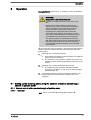
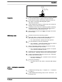
t
1
t
2
Q
1
Q
2
P_G_0071_SW
1. Use the
[Clickwheel]
to scroll through the continuous display
to check whether litres or gallons have been selected.
2. If the incorrect volume unit has been selected, correct it in
the
‘Menu / Information
è
Settings
è
System
è
Volume unit’
menu.
Calibration using a calibration factor
Calibration
Preparation
Operation
12

3. Check whether the capacity or stroke rate in the continuous
display is not too low for calibration.
4. Lead the suction hose into a measuring cylinder containing
the feed chemical – make sure that the discharge hose is
installed permanently (operating pressure, ...!).
5.
Prime the feed chemical (press
[Priming]
) if the suction
hose is empty.
1. Record the level in the measuring cylinder.
2.
Select the
‘Menu / Information
è
Settings
è
Calibration
è
Calibration’
menu and press the
[Clickwheel]
.
ð
The
‘Start calibration’
(PUSH) menu item appears.
3. To start calibration, press the
[Clickwheel]
.
ð
The
‘Calibrate ...’
menu item appears, the pump starts to
pump and indicates the number of strokes.
4. After a reasonable number of strokes (a minimum of 200),
use the
[Clickwheel]
to stop the pump.
ð
The
‘Calibration ended’
menu item appears. It requests
you to enter the calibration volume.
5. Determine the required metering volume (difference between
initial volume - remaining volume in the measuring cylinder).
6. Use the
[Clickwheel]
to enter this volume in the
‘Calibration
ended’
menu item and close.
ð
The pump switches to the
‘Calibration result’
menu item -
the pump is calibrated.
7. Press the
[Clickwheel]
.
ð
The pump returns to the
‘Menu / Information
è
Settings’
menu.
6.1.1.2 Adjusting the concentration
1.
Calibrate the metering pump,
Ä Chapter 6.1.1.1 ‘Calibration’
on page 11
2. Check whether the metering pump is set to
‘Automatic’
-
‘on’
metering mode.
3. Select
‘Manual’
-
‘Operating mode’
(settings potentially con‐
figured in other operating modes remain saved).
4. Select
‘Concentration’
in the
‘Set up’
menu.
5. Set
‘active’
in the
‘Concentration control’
menu item and
press the
[Clickwheel]
.
6. Set the
‘Main medium flow’
(of the pipework) and then press
the
[Clickwheel]
.
7. Set the
‘Feed chemical mass concentration’
and press the
[Clickwheel]
➨ 12 %.
8. Set the (mass)
‘Feed chemical density’
and press the
[Clickwheel]
➨ 1.21
ð
The
‘Concentration’
menu appears.
9.
Press
[Menu]
.
ð
A continuous display appears.
Calibration process
Operation
13

10. Turn the
[Clickwheel]
to go to the "Concentration" continuous
display (ppm or %).
11. Enter the required mass concentration of feed chemical in
the main flow by pressing and turning the
[Clickwheel]
.
6.1.2 Control using the contact water meter
6.1.2.1 Calibration
‘Menu / Information
è
Settings
è
Calibration
è
...’
Calibration - precision
Normally the pump does not have to be calibrated.
However, the pump should be calibrated for pre‐
cise metering.
With individual pumps in the product range, the
capacity can systematically deviate by -5% to
+10% from the specified capacity. A reproducibility
of ±2 % from the specified capacity remains as a
deviation after calibration.
Calibration influences the menu
In ‘Auto’ - ‘off’ dosing mode: Some menus only
appear if the pump has been calibrated.
1.
Select the
‘Menu / Information
è
Settings
è
Calibration
è
Calibration factor’
menu and press the
[Clickwheel]
.
ð
The
‘Calibration factor’
menu item appears.
2. Use the
[Clickwheel]
to enter the required
‘Calibration factor’
.
ð
The
‘Calibration factor’
menu item appears for confirma‐
tion.
‘Calibr. factory’ = Actual value (measured) / Set‐
point (required)
WARNING!
If the feed chemical is hazardous, take appropriate
safety precautions when performing the following
calibration instructions. Observe the material safety
data sheet for the feed chemical!
Calibration using a calibration factor
Calibration
Operation
14

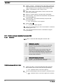
t
1
t
2
Q
1
Q
2
P_G_0071_SW
1. Use the
[Clickwheel]
to scroll through the continuous display
to check whether litres or gallons have been selected.
2. If the incorrect volume unit has been selected, correct it in
the
‘Menu / Information
è
Settings
è
System
è
Volume unit’
menu.
3. Check whether the capacity or stroke rate in the continuous
display is not too low for calibration.
4. Lead the suction hose into a measuring cylinder containing
the feed chemical – make sure that the discharge hose is
installed permanently (operating pressure, ...!).
5.
Prime the feed chemical (press
[Priming]
) if the suction
hose is empty.
1. Record the level in the measuring cylinder.
2.
Select the
‘Menu / Information
è
Settings
è
Calibration
è
Calibration’
menu and press the
[Clickwheel]
.
ð
The
‘Start calibration’
(PUSH) menu item appears.
3. To start calibration, press the
[Clickwheel]
.
ð
The
‘Calibrate ...’
menu item appears, the pump starts to
pump and indicates the number of strokes.
4. After a reasonable number of strokes (a minimum of 200),
use the
[Clickwheel]
to stop the pump.
ð
The
‘Calibration ended’
menu item appears. It requests
you to enter the calibration volume.
5. Determine the required metering volume (difference between
initial volume - remaining volume in the measuring cylinder).
6. Use the
[Clickwheel]
to enter this volume in the
‘Calibration
ended’
menu item and close.
ð
The pump switches to the
‘Calibration result’
menu item -
the pump is calibrated.
7. Press the
[Clickwheel]
.
ð
The pump returns to the
‘Menu / Information
è
Settings’
menu.
6.1.2.2 Adjusting the concentration
1.
Calibrate the metering pump,
Ä Chapter 6.1.1.1 ‘Calibration’
on page 11
2. Check whether the metering pump is set to
‘Automatic’
-
‘on’
metering mode.
Preparation
Calibration process
Procedure
Operation
15

3. Select
‘Contact’
-
‘Operating mode’
and simply confirm the
associated menu items with the
[Clickwheel]
(settings poten‐
tially configured in other operating modes remain saved).
4. Select
‘Concentration’
in the
‘Set up’
menu.
5. Set
‘active’
in the
‘Concentration control’
menu item and
press the
[Clickwheel]
.
6. Set the
‘Contact distance’
and press the
[Clickwheel]
.
7. Set the (mass)
‘Feed chemical concentration’
and press the
[Clickwheel]
➨ 12 %.
8. Set the (mass)
‘Feed chemical density’
and press the
[Clickwheel]
➨ 1.21.
ð
The
‘Concentration’
menu appears.
9.
Press
[Menu]
.
ð
A continuous display appears.
10. Turn the
[Clickwheel]
to go to the "Concentration" continuous
display (ppm or %).
11. You can enter the desired mass concentration using the
[Clickwheel]
.
6.1.3 Control using an inductive flow meter IDM
6.1.3.1 Calibration
‘Menu / Information
è
Settings
è
Calibration
è
...’
Calibration - precision
Normally the pump does not have to be calibrated.
However, the pump should be calibrated for pre‐
cise metering.
With individual pumps in the product range, the
capacity can systematically deviate by -5% to
+10% from the specified capacity. A reproducibility
of ±2 % from the specified capacity remains as a
deviation after calibration.
Calibration influences the menu
In ‘Auto’ - ‘off’ dosing mode: Some menus only
appear if the pump has been calibrated.
1.
Select the
‘Menu / Information
è
Settings
è
Calibration
è
Calibration factor’
menu and press the
[Clickwheel]
.
ð
The
‘Calibration factor’
menu item appears.
2. Use the
[Clickwheel]
to enter the required
‘Calibration factor’
.
ð
The
‘Calibration factor’
menu item appears for confirma‐
tion.
Calibration using a calibration factor
Operation
16

‘Calibr. factory’ = Actual value (measured) / Set‐
point (required)
WARNING!
If the feed chemical is hazardous, take appropriate
safety precautions when performing the following
calibration instructions. Observe the material safety
data sheet for the feed chemical!
t
1
t
2
Q
1
Q
2
P_G_0071_SW
1. Use the
[Clickwheel]
to scroll through the continuous display
to check whether litres or gallons have been selected.
2. If the incorrect volume unit has been selected, correct it in
the
‘Menu / Information
è
Settings
è
System
è
Volume unit’
menu.
3. Check whether the capacity or stroke rate in the continuous
display is not too low for calibration.
4. Lead the suction hose into a measuring cylinder containing
the feed chemical – make sure that the discharge hose is
installed permanently (operating pressure, ...!).
5.
Prime the feed chemical (press
[Priming]
) if the suction
hose is empty.
1. Record the level in the measuring cylinder.
2.
Select the
‘Menu / Information
è
Settings
è
Calibration
è
Calibration’
menu and press the
[Clickwheel]
.
ð
The
‘Start calibration’
(PUSH) menu item appears.
3. To start calibration, press the
[Clickwheel]
.
ð
The
‘Calibrate ...’
menu item appears, the pump starts to
pump and indicates the number of strokes.
4. After a reasonable number of strokes (a minimum of 200),
use the
[Clickwheel]
to stop the pump.
ð
The
‘Calibration ended’
menu item appears. It requests
you to enter the calibration volume.
5. Determine the required metering volume (difference between
initial volume - remaining volume in the measuring cylinder).
6. Use the
[Clickwheel]
to enter this volume in the
‘Calibration
ended’
menu item and close.
ð
The pump switches to the
‘Calibration result’
menu item -
the pump is calibrated.
Calibration
Preparation
Calibration process
Operation
17

7. Press the
[Clickwheel]
.
ð
The pump returns to the
‘Menu / Information
è
Settings’
menu.
6.1.3.2 Adjusting the analogue signal
1.
Calibrate the metering pump,
Ä Chapter 6.1.1.1 ‘Calibration’
on page 11
2. Check whether the metering pump is set to
‘Automatic’
-
‘on’
metering mode.
3. Select
‘Analogue’
operating mode and confirm with the
[Clickwheel]
.
4. Set
‘0..20 mA’
or
‘4..20 mA’
in the
‘Select analogue’
menu
item and press the
[Clickwheel]
.
5. Select
‘Concentration’
in the
‘Set up’
menu.
6. Set
‘active’
in the
‘Concentration control’
menu item and
press the
[Clickwheel]
.
7. Set the
‘Max.throughput main medium’
(of the pipework) and
press the
[Clickwheel]
. (It is then assigned to the current
value of 20 mA.)
8. Set the (mass)
‘Feed chemical concentration’
and press the
[Clickwheel]
.
9. Set the (mass)
‘Feed chemical density’
and press the
[Clickwheel]
.
ð
The
‘Concentration’
menu appears.
10.
Press
[Menu]
.
ð
A continuous display appears.
11. Turn the
[Clickwheel]
to go to the "Concentration" continuous
display (ppm or %).
12. You can enter the desired mass concentration using the
[Clickwheel]
.
Procedure
Operation
18

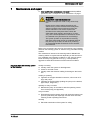
7 Maintenance and repair
n User qualification, maintenance and repair: trained qualified
personnel, see
Ä Chapter 2.4 ‘User qualification’ on page 7
WARNING!
Danger from hazardous substances!
Possible consequence: Fatal or very serious inju‐
ries.
Please ensure when handling hazardous sub‐
stances that you have read the latest safety data
sheets provided by the manufacture of the haz‐
ardous substance. The actions required are
described in the safety data sheet. Check the
safety data sheet regularly and replace, if neces‐
sary, as the hazard potential of a substance can be
re-evaluated at any time based on new findings.
The system operator is responsible for ensuring
that these safety data sheets are available and that
they are kept up to date, as well as for producing
an associated hazard assessment for the worksta‐
tions affected.
Refer to the operating instructions for the metering pump installed
and flush the metering system in advance using a suitable flushing
medium.
The maintenance interval of the metering station: Maintain the
metering station at regular intervals depending on the feed chem‐
ical, installation and operating conditions. In the event of serious
loads caused by long periods of use (e.g. 3-shift operation),
aggressive chemicals and external environmental conditions.
weekly to monthly:
n Visually check the system for leak-tightness.
n Check for unusual noises.
n Visually check the electrical cabling for damage to the insula‐
tion.
monthly to quarterly
n Tightness of the pipe threaded connectors, union nuts on fit‐
tings and pumps.
n Tightness of the fixing bolts (holding the pump on the bracket,
pipe clamps, flanges etc.).
quarterly to every 6 months
n Maintain the pump in accordance with the operating instruc‐
tions for the pump (see appendix)
every 6 months
n Dismantle the back pressure valve and check the internal com‐
ponents, particularly the diaphragm and the valve seat seal,
referring to their operating instructions.
annually
n Electrical examination of the system for safety.
Regularly check the metering system
for the following:
Maintenance and repair
19

The metering pumps can only be flushed from the suction side to
the discharge site.
1. Connect the suction lance to the flushing medium. Make sure
that you use a flushing medium that does not cause serious
chemical reactions with any residual feed chemical. To this
end, refer to the material safety data sheet for the feed chem‐
ical and the material safety data sheet for the flushing
medium.
2. Collect the contaminated flushing medium in a storage tank
and dispose of it in accordance with local regulations. To this
end, refer to the material safety data sheet for the feed chem‐
ical and the material safety data sheet for the flushing
medium.
Please use the operating instructions for the metering pump and
back pressure valves to rectify any functional faults.
Flushing:
Troubleshooting
Maintenance and repair
20
La pagina si sta caricando...
La pagina si sta caricando...
La pagina si sta caricando...
La pagina si sta caricando...
La pagina si sta caricando...
La pagina si sta caricando...
La pagina si sta caricando...
La pagina si sta caricando...
-
 1
1
-
 2
2
-
 3
3
-
 4
4
-
 5
5
-
 6
6
-
 7
7
-
 8
8
-
 9
9
-
 10
10
-
 11
11
-
 12
12
-
 13
13
-
 14
14
-
 15
15
-
 16
16
-
 17
17
-
 18
18
-
 19
19
-
 20
20
-
 21
21
-
 22
22
-
 23
23
-
 24
24
-
 25
25
-
 26
26
-
 27
27
-
 28
28


ProMinent 1081318 Assembly And Operating Instructions Manual
- Tipo
- Assembly And Operating Instructions Manual
in altre lingue
- English: ProMinent 1081318
Documenti correlati
-
ProMinent DULCO flex Control-DFYa Operating Instructions Manual
-
-
-
-
-

