
86-755-21612590
1-833-629-4832 (North America)
www.topdon.com
@TopdonOcial
@TopdonOcial
For Services and Support
USER MANUAL
ARTILINK 400
OBD II & EOBD Scan Tool

2
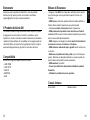
Welcome
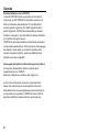
About ArtiLink 400
Compatibility
Thank you for purchasing ArtiLink 400. If any issues arise during
the use of this product, please contact support@topdon.com.
TOPDON ArtiLink400 serves as a full-featured OBD II scanner, able
to turn o check engine lights, clear codes, reset monitors, check
emission systems, and pinpoint basic car issues. It is compatible
with most 1996 and newer vehicles, and is designed to provide the
best diagnostic experiences for DIY users and mechanics.
ArtiLink 400 supports the following OBD II protocols:
• J1850 PWM
• J1850 VPW
• ISO9141
• KWP2000
• CAN
English
EN

3 4
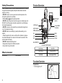
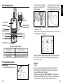
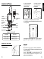
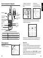
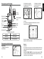
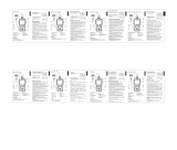
Product Overview
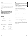
Pending DTCs
No DTCs
Permanent DTCs
Solid Green
Solid Yellow
Solid Red
A Guide to LED Indicator:
Back
Right
Down
LED Indicator
LCD Screen
I/M Readiness Button
Left
OK
Up
16-pin OBD II
Connector
Mini USB Port
LED Light
Button
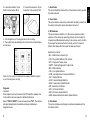
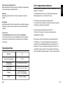
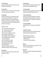
Function Overview
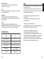
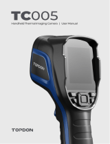
Preparations
1. Turn the ignition o.
What is Included
Safety Precautions
ArtiLink 400 User Manual
• ONLY operate the test in a well-ventilated area since the vehicle
may produce harmful gases,and particulate matter when the
engine is running.
• DO NOT smoke or use any source of electrical sparks or re
during the operation to avoid res.
• Wear safety goggles during the operation.
• DO NOT place the product near the engine or exhaust pipe, and
DO NOT touch the engine during the operation to avoid damage
from high temperatures.
• DO NOT connect or disconnect the product while the ignition is
on or the engine is running.
• DO NOT wear loose clothing or jewelry while working on an
engine.
• Keep the product dry, clean, and free from oil/water or grease.
Use a mild detergent on a clean cloth to clean the outside of the
product when necessary.
• DO NOT disassemble the product.
• Keep product away from children and pets.
• Use product only as intended.
EN

5 6
1. Read Codes
This option identies which section of the emission control system
has malfunctioned.
2. Erase Codes
This option erases codes in the vehicle after retrieving codes from
the vehicle and certain repairs have been carried out.
3. I/M Readiness
This option checks whether or not the various emission-related
systems on the vehicle are operating properly, and are ready for
Inspection and Maintenance testing. It also can be used to conrm
that a repair has been performed correctly, and/or to check for
Monitor Run Status after the repair has been performed.
Explanation of terms:
• MIL - Malfunction Indicator Light
• IGN - The Ignition Method of the Vehicle
• DTC - Diagnostic Trouble Code
• PdDTC -Pending Diagnostic Trouble Code
• MIS - Misre Monitor
• FUE - Fuel System Monitor
• CCM - Comprehensive Components Monitor
• CAT - Catalyst Monitor
• HCAT - Heated Catalyst Monitor
• EVAP - Evaporative System Monitor
• AIR -Secondary Air Monitor
• O2S - O2 Sensor Monitor
• HRT- O2 Sensor Heater Monitor
• EGR - Exhaust Gas Recirculation System Monitor
4. Data Stream
This option retrieves and displays live data and parameters from
the vehicle's ECU.
2. Locate the vehicle's 16-pin
Data Link Connector (DLC).
3. Connect the scanner's 16-pin
Connector to the vehicle's DLC.
4. Turn the ignition on. The engine can be o or running.
5. The scanner will automatically link to the vehicle and will display
a main menu.
Note: Do not connect or disconnect the scanner while the ignition
is on or the engine is running.
Diagnosis
Important:
Never replace a part only based on the DTC denition. Always refer
to the vehicle's service manual for detailed instructions.
Select "OBD II / EOBD" in main menu and press "OK". The scanner
will automatically check the vehicle's computer and display a
diagnostic menu.
EN

7 8
Help
This option enables you to check the information of the scanner
and OBD.
Setup
This option enables you to change language, set the measurement
unit, turn on/o the recording function and key tone.
Note:
If you set the recording mode to OFF, the Review function will be
unavailable and the DTCs, Data Streams, and Freeze Frames will
not be stored after every test.
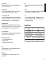
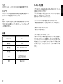
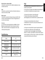
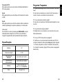
Specications
9~18V
147.5*79*24.3 mm (5.8*3.1*1.0 inches)
2.4''
-20°C~70°C (-4°F~158°F)
-10°C~50°C (14°F~122°F)
230g (8.11oz)
Display
Storage Temperature
Input Voltage
Dimensions
Working Temperature
Weight
5. Freeze Frame
This option takes the snapshot of the operating conditions when
an emission-related fault occurs.
6. O2 Sensor Test
This option retrieves O2 sensor monitor test results of the most
recently completed tests from your vehicle's computer.
7. On-Board Monitor Test
This option retrieves test results for emission-related powertrain
components and systems that are not continuously monitored. The
tests available are determined by the vehicle manufacturer.
8. EVAP System Test
This option retrieves test results for emission-related powertrain
components and systems that are not continuously monitored. The
tests available are determined by the vehicle manufacturer.
9. Vehicle Information
This option retrieves a list of information (provided by the vehicle
manufacturer) from the vehicle's computer.
This information may include:
• VIN (Vehicle identication Number).
• CID (Calibration ID).
• CVN (Calibration Verication Number).
Review
This option is designed to review or delete the recorded DTCs,
Data Streams and Freeze Frames.
DTC Lookup
This option enables you to view the detailed denition of the
retrieved DTCs.
EN

9 10
Warranty
TOPDON One Year Limited Warranty
TOPDON warrants to its original purchaser that TOPDON
products will be free from defects in material and workmanship
for 12 months from the date of purchase (Warranty Period). For
the defects reported during the Warranty Period, TOPDON will,
according to its technical support analysis and conrmation, either
repair or replace the defective part or product.
The TOPDON shall not be liable for any incidental or consequential
damages arising from the use, misuse, or mounting of the device.
Some states do not allow limitation on how long an implied
warranty lasts, so the above limitations may not apply to you.
This limited warranty is void under the following conditions:
Misused, disassembled, altered or repaired by unauthorized stores
or technicians.
Careless handling and violation of operation.
Notice:
All information in this manual is based on the latest information
available at the time of publication and no warranty can be made
for its accuracy or completeness. TOPDON reserves the right to
make changes at any time without notice.
FAQ
Q: The system stops/freezes when reading a data stream. What
should I do?
A: It may be caused by a loose connector. Please unplug the
connector and plug it in again to retry.
Q: Why does the screen ash during ignition?
A: It may be caused by electromagnetic interference,
which is normal.
Q: Why are there so many fault codes?
A: Usually, it's caused by a poor connection or a ground fault.
Q: Why can't the DTCs be erased?
A: Conrm the malfunction related to DTCs has been properly
xed. Next, switch the ignition OFF. Wait for 1-3 minutes, then start
the vehicle. Finally, try to run "Read Codes" again. (Some DTCs
can only be erased in this way.)
EN

11
FCC WARNINGS
This device complies with Part 15 of the FCC Rules. Operation
is subject to the following two conditions: (1) this device may not
cause harmful interference, and (2) this device must accept any
interference received, including interference that may cause
undesired operation.
Note: This equipment has been tested and found to comply
with the limits for a Class B digital device, pursuant to Part
15 of the FCC Rules. These limits are designed to provide
reasonable protection against harmful interference in a residential
installation. This equipment generates, uses and can radiate radio
frequency energy and, if not installed and used in accordance
with the instructions, may cause harmful interference to radio
communications. However, there is no guarantee that interference
will not occur in a particular installation. If this equipment does
cause harmful interference to radio or television reception, which
can be determined by turning the equipment o and on, the user is
encouraged to try to correct the interference by one or more of the
following measures:
Reorient or relocate the receiving antenna.
Increase the separation between the equipment and receiver.
Connect the equipment into an outlet on a circuit dierent from that
to which the receiver is connected.
Consult the dealer or an experienced radio/TV technician for help.
Español

13 14
Bienvenido
Acerca de ArtiLink 400
Compatibilidad
Gracias por comprar ArtiLink 400. Si surge cualquier problema
durante el uso de este producto, le invitamos a ponerse en contacto
con support@topdon.com para obtener soporte técnico ocial.
TOPDON ArtiLink400 sirve como un escáner OBD II con todas
las funciones, capaz de apagar las luces de vericación del motor,
borrar códigos, restablecer monitores, comprobar sistemas de
emisiones y determinar con precisión problemas básicos del
automóvil. Es compatible con la mayoría de los vehículos de
1996 y posteriores, y está diseñado para proporcionar las mejores
experiencias de diagnóstico para los usuarios DIY y mecánicos.
ArtiLink 400 soporta los siguientes protocolos OBD II :
• J1850 PWM
• J1850 VPW
• ISO9141
• KWP2000
• CAN
Lista de Empaque
Precauciones de Seguridad
ArtiLink 400 Manual de Usuario
• SOLO realice la prueba en un área bien ventilada, ya que el
vehículo puede producir gases nocivos y partículas cuando el
motor está funcionando.
• NO fume ni utilice ninguna fuente de chispas eléctricas o fuego
durante la operación para evitar incendios.
• Utilice gafas de seguridad durante la operación.
• NO coloque el producto cerca del motor o del tubo de escape,
y NO toque el motor durante la operación para evitar daños por
altas temperaturas.
• NO conecte ni desconecte el producto mientras la ignición esté
encendida o el motor esté funcionando.
• NO utilice ropa holgada o joyas mientras trabaja en un motor.
• Mantenga el producto seco, limpio y libre de aceite / agua o
grasa. Utilice un detergente ligero en un paño limpio para limpiar
el exterior del producto cuando sea necesario.
• NO desarme el producto.
• Mantenga el producto fuera del alcance de los niños
y las mascotas.
• Utilice el producto solo para el n para el que fue diseñado.
ES

15 16
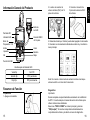
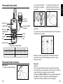
Información General del Producto
Volver
Derecha
Abajo
Indicador LED
Pantalla LCD
Botón de
Preparación I / M
Izquierda
OK
Arriba
Conector OBD II
de 16 pines
Puerto mini USB
Botón de
Luz LED
DTC pendientes
Sin DTC
DTC permanentes
Verde jo
Amarillo jo
Rojo Fijo
Una Guía para el Indicador LED:
Resumen de Función
Preparativos
1. Apague el encendido.
2. Localice el conector de
enlace de datos (DLC) de 16
pines del vehículo.
3. Conecte el conector de
16 pines del escáner al DLC
del vehículo.
4. Encienda el arranque. El motor puede estar apagado o funcionando.
5. El escáner se vinculará automáticamente al vehículo y mostrará un
menú principal.
Nota: No conecte ni desconecte el escáner mientras el arranque
esté encendido o el motor esté funcionando.
Diagnóstico
Importante:
Nunca reemplace una pieza basándose únicamente en la denición
de DTC. Consulte siempre el manual de servicio del vehículo para
obtener instrucciones detalladas.
Seleccione "OBD II / EOBD" en el menú principal y presione
"OK (Aceptar)". El escáner comprobará automáticamente la
computadora del vehículo y mostrará un menú de diagnóstico.
ES

17 18
1. Leer códigos
Esta opción identica qué sección del sistema de control de
emisiones ha fallado.
2. Borrar códigos
Esta opción borra los códigos en el vehículo después de recuperar
los códigos del vehículo y se han realizado ciertas reparaciones.
3. Preparación I / M
Esta opción comprueba si los diversos sistemas relacionados con
las emisiones en el vehículo están funcionando correctamente
y están listos para las pruebas de inspección y mantenimiento.
También se puede utilizar para conrmar que se ha realizado
una reparación correctamente y / o para comprobar el estado
de ejecución del monitor después de que se haya realizado la
reparación.
Explicación de términos:
• MIL - Luz Indicadora de mal Funcionamiento
• IGN - El Método de Encendido del Vehículo
• DTC - Código de Diagnóstico de Problemas
• PdDTC - Código de Diagnóstico de Problema Pendiente
• MIS - Monitor de Falla de Arranque
• FUE - Monitor del Sistema de Combustible
• CCM - Monitor de Componentes Integrados
• CAT - Monitor de Catalizador
• HCAT - Monitor de Catalizador Calentado
• EVAP - Monitor del Sistema Evaporativo
• AIR - Monitor de Aire Secundario
• O2S - Monitor del Sensor de Oxígeno
• HRT- Monitor del calentador del Sensor de Oxígeno
• EGR - Monitor del Sistema de Recirculación de Gases de Escape
4. Flujo de datos
Esta opción recupera y muestra datos y parámetros en vivo de la
ECU del vehículo.
Revisar
Esta opción está diseñada para revisar o eliminar los DTC, ujos de
datos y cuadros congelados grabados.
Búsqueda de DTC
Esta opción le permite ver la denición detallada de los DTC
recuperados.
5. Congelar Cuadro
Esta opción toma una instantánea de las condiciones de
operación cuando ocurre una falla relacionada con las emisiones.
6. Prueba del Sensor de O2
Esta opción recupera los resultados de la prueba del monitor del
sensor de O2 de las pruebas completadas más recientemente de
la computadora de su vehículo.
7. Prueba de Monitor a bordo
Esta opción recupera los resultados de las pruebas para los
componentes y sistemas del tren motriz relacionados con las
emisiones que no se monitorean continuamente. Las pruebas
disponibles son determinadas por el fabricante del vehículo.
8. Prueba del Sistema EVAP
Esta opción inicia una prueba de fugas para el sistema EVAP del
vehículo.
9. Información del Vehículo
Esta opción recupera una lista de información (proporcionada por
el fabricante del vehículo) de la computadora del vehículo.
Esta información puede incluir:
• VIN (Número de Identicación del Vehículo).
• CID (ID de Calibración).
• CVN (Número de Vericación de Calibración).
ES

19 20
Ayuda
Esta opción le permite comprobar la información del escáner y OBD.
Conguración
Esta opción le permite cambiar el idioma, congurar la unidad de
medida, encender / apagar la función de grabación y el tono de
las teclas.
Nota:
Si usted congura el modo de grabación en APAGADO, la función
de revisión no estará disponible y los DTC, los ujos de datos y los
cuadros congelados no se almacenarán después de cada prueba.
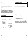
Especicaciones
9~18V
147,5 * 79 * 24,3 mm
(5,8 * 3,1 * 1,0 pulgadas)
2.4''
-20°C~70°C (-4°F~158°F)
-10°C~50°C (14°F~122°F)
230g (8.11oz)
Monitor
Temperatura de
almacenamiento
Voltaje de entrada
Dimensiones
Temperatura de
funcionamiento
Peso
Preguntas más Frecuentes
P: El sistema se detiene / congela al leer un ujo de datos. ¿Qué
tengo que hacer?
R: Puede ser causado por un conector suelto. Por favor
desenchufe el conector y vuelva a enchufarlo para volver
a intentarlo.
P: ¿Por qué la pantalla parpadea durante el encendido?
R: Puede deberse a interferencias electromagnéticas, lo cual
es normal.
P: ¿Por qué hay tantos códigos de falla?
R: Por lo general, es causado por una mala conexión o una falla
a tierra.
P: ¿Por qué no se pueden borrar los DTC?
R: Conrme que el mal funcionamiento relacionado con los DTC
se haya solucionado correctamente. A continuación, apague el
encendido. Espere de 1 a 3 minutos, luego encienda el vehículo.
Finalmente, intente ejecutar "Leer códigos" nuevamente. (Algunos
DTC solo se pueden borrar de esta manera).
ES

21
Garantía
Garantía limitada de un año TOPDON
La Compañía TOPDON garantiza a su comprador original que
los productos TOPDON estarán libres de defectos en materiales
y mano de obra durante 12 meses a partir de la fecha de compra
(Período de garantía). Para los defectos informados durante el
Período de garantía, TOPDON, de acuerdo con su análisis y
conrmación de soporte técnico, reparará o reemplazará la pieza
o el producto defectuoso.
TOPDON no será responsable de ningún daño incidental o
consecuente que surja del uso, mal uso o montaje del dispositivo.
Algunos estados no permiten la limitación de la duración de una
garantía implícita, por lo que las limitaciones anteriores pueden no
aplicarse en su caso.
Esta garantía limitada es nula bajo las siguientes condiciones:
Mal uso, desarmado, alterado o reparado por una persona que
no sea especialista en reparaciones técnicas de la compañía
TOPDONManejo descuidado y violación de la operación.
Aviso: Toda la información en este manual se basa en la
información más reciente disponible en el momento de la
publicación y no se puede garantizar su exactitud o certeza.
TOPDON se reserva el derecho de realizar cambios en cualquier
momento sin previo aviso.
Deutsche

23 24
Willkommen
Über ArtiLink 400
Kompatibilität
Vielen Dank, dass Sie sich für ArtiLink 400 entschieden haben.
Falls während der Inbetriebnahme dieses Produkts Probleme
auftreten, wenden Sie sich bitte an support@topdon.com, um
oziellen technischen Support zu erhalten.
TOPDON ArtiLink400 dient als mit allen Funktionen ausgestatteter
OBD II -Scanner, der in der Lage ist, Motorlichter auszuschalten,
Codes zu löschen, Monitore zurückzusetzen, Abgassysteme zu
überprüfen und grundlegende Fahrzeugprobleme zu lokalisieren.
Es ist mit den meisten Fahrzeugen kompatible, die nach 1996
hergestellt wurden, und wurde entwickelt, um Heimwerkern und
Mechanikern die besten Diagnoseerlebins bereitzustellen.
ArtiLink 400 unterstützt die folgenden OBD II -Protokolle:
• J1850 PWM
• J1850 VPW
• ISO9141
• KWP2000
• CAN
Paketumfang
Sicherheitshinweise
ArtiLink 400 Bedienungsanleitung
• Testen Sie das Fahrzeug NUR in einem gut belüfteten Bereich,
da das Fahrzeug bei laufendem Motor Gesundheitsschädliche
Gase und Feinstäube produzieren kann.
• Während des Betriebs NICHT rauchen und keine elektrische
Ausrüstung einschalten oder Feuerquellen verwenden, um Brände
zu vermeiden.
• Beim Betrieb Schutzbrille aufsetzen.
• Verwenden Sie das Prüfgerät nicht in der Nähe des Motors
oder Auspus und berühren Sie den Motor nicht, da diese
Bereiche so heiß sind, dass dies zu Verbrennungen führen würde
• Bitte schließen Sie keine Prüfgeräte an oder trennen Sie
diese nicht, solange die Zündung eingeschaltet ist oder der
Motor läuft.
• Tragen Sie keine losen oder herunterhängenden
Kleidungsstücke oder Schmuck bei Arbeiten an sich
bewegenden Teilen.
• Das Produkt muss sauber und trocken, frei von Öl und
Schmutz sein. Bitte reinigen Sie das Gehäuse mit einem weichen
Tuch, leicht angefeuchtet mit einem milden Reinigungsmittel.
• Önen Sie niemals das Gerät.
• Bitte außerhalb der Reichweite von Kindern und Tieren
aufbewahren.
• Benutzen Sie das Gerät nur für den vorgesehenen
Verwendungszweck.
DE

25 26
Produktübersicht
anstehende Fehlercodes
Keine Fehlercodes
permanente Fehlercodes
Beständig grün
Beständig gelb
Beständig rot
Erklärung der LED-Anzeigen:
Funktionsübersicht
Vorbereitung
1. Schalten Sie die Zündung aus.
2.Suchen Sie den 16-poligen
Data Link Connector (DLC)
des Fahrzeugs.
3. Verbinden Sie den 16-poligen
Stecker des Scanners mit der
DLC Schnittstelle des Fahrzeugs.
4. Schalten Sie die Zünding ein. Der Motor kann laufen oder
ausgeschaltet sein.
5. Der Scanner verbindet sich automatisch mit dem Fahrzeug und
das Hauptmenü wird angezeigt.
Hinweis: Verbinden Sie das Diagnosegerät bzw. trennen Sie das
Gerät nicht vom. Fahrzeug, wenn die Zündung eingeschaltet ist
bzw. der Motor läuft.
Diagnose
Wichitig:
Ersetzen Sie niemals Komponenten basierend auf der DTC-
Fehlerdenition. Die detaillierten Informationen nden Sie im
Service-Handbuch des Fahrzeugs.
Wählen Sie im Hauptmenü „OBD II / EOBD“ und drücken Sie
anschließend auf „OK“. Der Scanner überprüft automatisch den
Computer des Fahrzeugs und zeigt ein Diagnosemenü an.
Zurück
Rechts
Unten
LED-Anzeige
LCD Bildschirm
I/M-
Bereitschaftstaste
Links
OK
Oben
16-polige OBD II
Steckverbindung
Mini-USB-Anschluss
LED-
Lichttaste
DE

27 28
1. Fehlercode Lesen
Mithilfe dieser Funktion können Sie herausnden, welcher
Abschnitt der Abgasreinigungsanlage eine Fehlfunktion hat.
2. Fehlercode löschen
Nach dem Lesen der abgerufenen Codes des Fahrzeuges und
nachdem bestimmte Reparaturen durchgeführt wurden, können
Sie diese Funktion verwenden, um die Codes vom Fahrzeug zu
löschen.
3. I/M Bereitschaft
I/M Bereitschaft zeigt an, ob die verschiedenen
emissionsrelevanten Systeme am Fahrzeug ordnungsgemäß
betrieben werden oder nicht, und ob sie für den Untersuchungs-
und Wartungstest bereit sind. Es kann auch verwendet werden, um
zu bestätigen, dass eine Reparatur korrekt durchgeführt wurde,
und/oder um die Überwachung nach der Reparatur zu überprüfen.
Begriserklärung:
• MIL - Störungsanzeigeleuchte
• IGN – Die Zündmethode des Fahrzeugs
• DTC - Diagnose-Fehlercode
• PdDTC - Ausstehender Diagnose-Fehlercode
• MIS - Fehlzündungsmonitor
• FUE - Kraftstosystemmonitor
• CCM – Umfassender Komponentenmonitor
• CAT - Katalysatormonitor
• HCAT – Beheizter Katalysatormonitor
• EVAP – Verdunstungssystemmonitor
• AIR -Sekundärluftmonitor
• O2S - O2-Sensormonitor
• HRT-O2-Sensor-Heizungsmonitor
• AGR – Überwachung des Abgasrückführungssystems
4. Datenstrom
Diese Option ruft auf und zeigt Live-Daten und Parameter vom
ECU des Fahrzeugs an.
5. Standbild
Bei einem emissionsbedingten Fehler werden bestimmte
Fahrzeugzustände vom Bordcomputer erfasst. FreezeDaten sind
eine Momentaufnahme der Betriebsbedingungen zum Zeitpunkt
eines emissionsbezogenen Fehlers.
6. O2 Sensortest
Die Ergebnisse des O2 Sensortests sind die Werte der letzten O2
Sensortests des ECUs.
7. On-Board Monitor Test
Mit dieser Funktion können die Ergebnisse der On-Board-
Diagnoseüberwachung für bestimmte abgassrelevante
Komponenten/Systeme ausgelesen werden. Die Tests werden
vom ahrzeughersteller festgelegt.
8. EVAP Systemtest
Die EVAP-Testfunktion erlaubt Ihnen, eine ichtheitsprüfung für das
EVAPSystem des Fahrzeuges zu initialisieren.
9. Fahrzeuginformation
Diese Option zeigt die Fahrzeuginformationen (vor Hersteller
bereitgestellt) des Boardcomputers an.
Diese Informationen sindz:
• VIN (Fahrzeugidentikationsnummer).
• CID (Kalibrierungs-ID).
• CVN (Kalibrierungsprüfnummer).
Verlauf
Diese Option wurde konzipiert, um die aufgezeichneten DTCs,
Datenströme und Standbilder zu überprüfen oder zu löschen.
DE

29 30
Spezikationen
9~18V
147.5*79*24.3 mm
(5.8*3.1*1.0 inches)
2.4''
-20°C~70°C (-4°F~158°F)
-10°C~50°C (14°F~122°F)
230g (8.11oz)
Anzeige
Lagertemperatur
Eingangsspannung
Abmessungen
Betriebstemperatur
Gewicht
F&A
F: Das System stoppt und beim Lesen des Datenstroms und friert
ein. Was ist der Grund?
A: Es kann durch einen gelockerten Stecker verursacht werden.
Bitte schalten Sie dieses Gerät aus und schließen Sie den Stecker
an und schalten Sie ihn wieder ein.
F: Der Bildschirm des Hauptgerätes blinkt beim Start der
Motorzündung.
A: Verursacht durch elektromagnetische Störungen. Die ist
normales Phänomen.
F: Warum gibt es so viele Fehlercodes?
A: Normalerweise wird es durch eine schlechte Verbindung oder
fehlerhafte Erdung des Schaltkreises verursacht.
F: Warum kann ich die Fehlercodes nicht löschen?
A: Bitte vergewissern Sie sich, dass die Störung im
Zusammenhang mit DTCs ordnungsgemäß behoben wurde. Als
nächstes schalten Sie die Zündung AUS. Warten Sie 1-3 Minuten
und starten Sie anschließend das Fahrzeug. Versuchen Sie
abschließend erneut, "Fehlercodes lesen" auszuführen. (Einige
DTCs können nur auf diese Weise gelöscht werden.)
DTC Nachschlagen
Mit dieser Option können Sie die detaillierte Denition der
abgerufenen DTCs anzeigen.
Hilfe
Mifhilfe dieser Option können Sie die Informationen des Scanners
und des OBD überprüfen.
Einstellung
Mit dieser Option können Sie die Zielsprache ändern, die
Maßeinheit einstellen, die Aufnahmefunktion und den Tastenton
ein-/ausschalten.
Hinweis:
Falls der Aufnahmemodus auf AUS gestellt wird, ist die
Verlaufsfunktion nicht verfügbar und die Fehlercodes, Datenströme
und Standbilder werden nicht nach jedem Test gespeichert.
DE

31
日本語
Garantie
TOPDON Einjährige beschränkte Garantie
Die Firma TOPDON garantiert ihrem Originalkäufer, dass TOPDON
Produkte für einen Zeitraum von 12 Monaten ab Kaufdatum frei
von Materialfehlern sowie von Verarbeitungsfehlern bleibt. Für die
während des Garantiezeitraums gemeldeten Mängel repariert oder
ersetzt TOPDON gemäß seiner Analyse und Bestätigung durch den
technischen Support das defekte Teil oder Produkt.
Der TOPDON haftet nicht für Neben- oder Folgeschäden, die durch
die Verwendung, den Missbrauch oder die Montage des Geräts
entstehen. In einigen Staaten ist eine Beschränkung der Dauer
einer impliziten Garantie nicht zulässig. Daher gelten die oben
genannten Einschränkungen möglicherweise nicht für Sie.
Der Garantieanspruch erlischt in den folgenden Fällen:
Missbrauch, Demontage, Änderung oder Reparatur durch einen
technischen Reparaturspezialisten, der nicht von TOPDON stammt.
Unachtsamer Umgang und Betriebsverletzung.
Hinweis: Die in diesem technischen Handbuch angegebenen
Informationen, Daten und Hinweise entsprachen dem neuesten
Stand zum Zeitpunkt der Veröentlichung. Wir übernehmen jedoch
keinerlei Garantie oder Gewähr für die Richtigkeit, Vollständigkeit
und Aktualität. TOPDON behält sich das Recht vor, jederzeit ohne
vorherige Ankündigung Änderungen vorzunehmen.

33 34
ご購入いただきありがとうございます
ArtiLink 400 について
互換性
ArtiLink 400 をご購入いただき、誠にありがとうございます。ご使用中
に何か問題がございましたら、ご遠慮なく [email protected] ま
でにお問い合わせください。
TOPDON ArtiLink400 は、チェックエンジンランプの消灯、故障コード
の消去、モニターのリセットなど、フル機能の OBD II コードリーダーとし
て機能し、エミッションシステムの動作確認や車の基本的な問題の特
定に役立ちます。1996 年以降のほとんどの OBD II システムの車両に対
応し、DIY ユーザーやメカニックに最高の診断体験を提供するように開
発されました。
ArtiLink 400 は以下の OBD II プロトコルに対応しています。
• J1850 PWM
• J1850 VPW
• ISO9141
• KWP2000
• CAN
パッケージリスト
安全上の注意事項
ArtiLink 400 ユーザーマニュアル
• エンジン稼働中は有毒ガスや微粒子が発生するため、換気の良い場
所の み で テストを 行 ってくだ さ い 。
• 火災にならないため、運転中に喫煙したり、電気火花や裸火を使用
したりをしないでください。
• 作業中は必ずゴーグルを 着 用してくだ さ い 。
• 高温によるけがを防ぐため、エンジンや排気管の近くに製品を置い
たり、運転中にエンジンに触れたりをしないでください。
• イグニッションスイッチがオンになっているとき、またはエンジンが
作動しているときは、この製品を接続または切断しないでください。
• エンジンを運転するときは、ゆったりした 服 や アクセ サリー を 着 用し
ないでください。
• 製品を乾燥した清 潔な状態にするためには、油 、水 や グ リ ース が 付
着 し な い よ う に し て く だ さ い 。ク リ ー ニ ン グ が 必 要 な 場 合 は 、中 性 洗 剤
をきれいな雑巾につけて、その雑巾で製品の外側をクリーニングしてく
ださい。
• 本製品を分解しないでください。
• 子供やペットから製品を遠ざけてください。
• 通常の方法のみ本製品を使用してください。
JP

35 36
JP
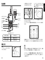
製品概要
保留中の DTCs
DTCs なし
永久の DTCs
緑ランプ点灯
黄色ランプ点灯
赤ランプ点灯
LED 指示灯について:
機能一覧
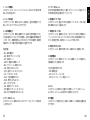
準備
1 .イ グ ニ ッ シ ョ ン ス イ ッ チ を オ
フ にしてくだ さ い 。
2 .車 両 の 16 ピ ン コ ネ ク タ
ー(DLC)を見つけてください。
3 .コ ー ド リ ー ダ ー の 1 6 ピ ン コ ネ
クターと車両の DLC コネクターを
接 続 してくだ さ い 。
4.イグニッションスイッチをオンにし、エンジンを起動したり、停止し
たりすることができます。
5 .コ ー ド リ ー ダ ー は 自 動 的 に 車 両 に 接 続 し 、メ イ ン メ ニ ュ ー が 表 示 さ
れま す。
注意事項:イグニッションスイッチが入っている状態やエンジンがかか
っている状態で、コードリーダーの接続や取り外しをしないでください。
診断
重 要:
故障コードの定義のみに基づいて部品を交換しないでください。 詳細
については、必ず車両の修理マニュアルを参照してください。
メインメニューで 「OBD II / EOBD」を選択し、「OK 」を 押 し ま す 。コ ー
ドリーダーは自動的に車両のコンピューターをチェックし、診断メニュ
ーを 表 示し ます。
戻る
右
下
LED 指示灯
LCD ディスプレイ
I/M 準備完了
ボタン
左
OK
上
16 ピンコ
ネクター
mini USB 端子
LED ラン
プボタン

37 38
JP
1 .コ ー ド の 読 取
このオプ ション は、エミッションコントロール システムのどの 部 分 が 故
障し た かを 特 定しま す。
2 .コ ー ド の 消 去
このオプションでは、車両から DTC sを取得し、適切な修理を行った
後に、DTC sをクリアすることができます。
3 .I / M 準 備 完 了
このオプションでは、車両に搭載されている様々な排気関連システム
が正常に動作しているかどうかを確認し、点検・整備試験の準備を行
い ま す 。 ま た 、故 障 修 理 が 正 しく 行 わ れ た か ど う か の 確 認 や 、故 障 修
理後のモニターの動作状況の確認にも使用できます。
用語定義:
• MIL - 故障警告灯
• IGN - 車両イグニッション方法
• DTC - 故障コード
• PdDTC - 保留中の故障コード
• MIS - イグニッション失敗モニター
• FUE - 燃料システムモニター
• CCM - 総合コンポーネントモニター
• CAT - カタリスト・モニター
• HCAT - 加熱式触媒モニター
• EVAP - 蒸発システムモニター
• AIR - 二次エアモニター
• O2S - 酸素センサーモニター
• HRT- 酸素センサーヒーターモニター
• EGR - 排ガス再循環システムモニター
4.データストリーム
このオプションは、車両の ECU からライブデータとパラメータを取得
して 表 示します。
5.フリーズフレーム
排 出 ガ ス 関 連 の 障 害 が 発 生 し た 場 合 、ス ク リ ー ン シ ョ ッ ト を 撮 っ て 、そ
の時の車の動作を記録するオプションです。
6 .酸 素 セ ン サ ー テ ス ト
このオプションは、直近に行われた酸素センサーモニターテストの結
果 を車 両 の E C U か ら取 得します。
7.車 載 モ ニ タ ー テ ス ト
このオプションは、継続的にモニターされていない排出ガス関連のパ
ワートレインのコンポーネントやシステムのテスト結果を検索します。
テストの実施可否は、車両のメーカーによって異なります。
8 .蒸 発 シ ス テ ム テ ス ト
このオプションは、車両の蒸発システムの漏れテストを開始します。
9 .車 両 情 報
このオプションは、車両のコンピュータから車両メーカーが提供する
情 報 検 索リストを取 得します。
下記の情報が含まれます。
• VIN(車体番号 )。
• CID(キャリブレーション ID)。
• CVN(キャリブレーション検証コード)。
レビュー
このオプションの目的は、記録された故障コード、データストリーム、
およびフリーズフレームを表示または削除することです。
DTC 検索
このオプションを使用すると、取得した故障コードの詳細な定義を表
示で きます。
La pagina si sta caricando...
La pagina si sta caricando...
La pagina si sta caricando...
La pagina si sta caricando...
La pagina si sta caricando...
La pagina si sta caricando...
La pagina si sta caricando...
La pagina si sta caricando...
La pagina si sta caricando...
La pagina si sta caricando...
La pagina si sta caricando...
La pagina si sta caricando...
La pagina si sta caricando...
La pagina si sta caricando...
La pagina si sta caricando...
La pagina si sta caricando...
La pagina si sta caricando...
La pagina si sta caricando...
La pagina si sta caricando...
La pagina si sta caricando...
La pagina si sta caricando...
La pagina si sta caricando...
-
 1
1
-
 2
2
-
 3
3
-
 4
4
-
 5
5
-
 6
6
-
 7
7
-
 8
8
-
 9
9
-
 10
10
-
 11
11
-
 12
12
-
 13
13
-
 14
14
-
 15
15
-
 16
16
-
 17
17
-
 18
18
-
 19
19
-
 20
20
-
 21
21
-
 22
22
-
 23
23
-
 24
24
-
 25
25
-
 26
26
-
 27
27
-
 28
28
-
 29
29
-
 30
30
-
 31
31
-
 32
32
-
 33
33
-
 34
34
-
 35
35
-
 36
36
-
 37
37
-
 38
38
-
 39
39
-
 40
40
-
 41
41
-
 42
42


in altre lingue
- français: Topdon ARTILINK 400 Manuel utilisateur
- español: Topdon ARTILINK 400 Manual de usuario
- Deutsch: Topdon ARTILINK 400 Benutzerhandbuch
- português: Topdon ARTILINK 400 Manual do usuário
- 日本語: Topdon ARTILINK 400 ユーザーマニュアル
Documenti correlati
-
 Topdon ArtiDiag800 BT Professional Diagnostic Tool Manuale utente
-
 Topdon ArtiDiag600 S Manuale utente
-
Topdon ArtiDiag500 S Manuale utente
-
 Topdon ArtiDiag Pro Guida Rapida
-
 Topdon ArtiLink500B Manuale utente
-
Topdon ArtiDiag800 BT Manuale utente
-
 Topdon ArtiLink600 Guida Rapida
-
 Topdon Phoenix Plus Manuale utente
-
 Topdon TC005 Manuale utente
-
 Topdon TC005 Manuale utente


