La pagina si sta caricando...

GATE 2 DG R1
(Cod. 23023025)
Sistemi Elettronici
di Apertura Porte e Cancelli
International registered trademark n. 804888
®
SEA S.p.A.
Zona industriale 64020 S.ATTO Teramo - (ITALY)
Tel. +39 0861 588341 r.a. Fax +39 0861 588344
www.seateam.com
67411385
Italiano
English
Français
Español
CENTRALE ELETTRONICA PER 1 O 2 MOTORI A 230V/115V
ELECTRONIC CONTROL UNIT FOR 1 OR 2 230V/115V MOTORS
ARMOIRE DE COMMANDE POUR 1 OU 2 MOTEURS EN 230V/115V
CENTRAL ELECTRÓNICA PARA 1 O 2 MOTORES A 230V/115V
Rev.07 - 12/2014

67411385
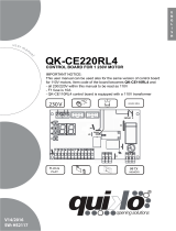
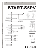
CN1 = Input/output connectors
CN2 = Limit switch, 24V~, Electrolock connector
CN3 = M1 Motors and capacitors connector
CN4 = M2 motors and capacitors connector
CN5 = Courtesy light output connector
CN6 = Power supply connector
CN7 = Encoder connector
CNA = RX Receiver connector
CNP = Porgramming connector
EXP = Expansion module connector / LE Card
JOLLY = Jolly and Jolly 2 connector
DS = Programming display
OK = Programming button
DOWN = Programming button
UP = Programming button
T1 = Motors piloting Triac
T2 = Motors piloting Triac
R1 = Motors comand relay
R2 = Courtesy light comand relay
R3 = Photocell autotest relay
R4 = Electrolock relay
F1 = Accessories 1A fuse
F2 = 6.3AT fuse on 230V/10AT on 115V
F3 = 6.3A Electrolock fuse
TR1 = Power transformer
24
English
GATE 2 DG R1
Sistemi Elettronici
di Apertura Porte e Cancelli
International registered trademark n. 804888
®
COMPONENTS
TECHNICAL SPECIFICATIONS
Control unit power supply: 230 Vac 50/60 Hz - 115Vac 50/60 Hz
Absorption in stand by: 30 mA
Environment temperature : -20°C +50°C
Specifications of external enclosure: 325,7 X 246 X 140
RECEIVER RX
168 mm
174 mm
CNP
CN7
EXP
JOLLY
CNA
CN6
CN5
CN4
CN3
CN1 CN2
F1
UP DOWN OK
F2
F3
R2
R1
T1 T2
TR1
R4
R3
DS
JOLLY-JOLLY2
1 2
ON
CN1
CNP
DS1
POTENC
M2
M1
1 2 4
P01 D1 P11 P02 D2 P12 I1
5 6 7
I2
GND
I3 I4
3 8 9 10 11
+ -
LE CARD
Rev.07 - 12/2014

67411385
English
GATE 2 DG R1
Sistemi Elettronici
di Apertura Porte e Cancelli
International registered trademark n. 804888
®
1
2
3 4
5 6
7 8
9
10
11
12
13
CN1
Start
Stop
Common
Antenna
START Pedestrian
Common
Photocell 1
Common
ANT COM STRT
STPD
STOP COM PH1 PH2
EDG1
COM 24VA FLS
Safety edge 1
Photocell 2
Lamp
(500mA max)
+
-
Safety edge 2
AUX
(24V 800mA
max)
24V~
(800 mA max)
24VPh
(800 mA max)
14
15
16 17
18 19
20 21
22
23
CN2
Electrolock
24
25
26 27
28
CN3
29
30
31 32
33
CN4
M1
M2
JUMPERS
1
2
3 4
5 6
7 8
9
10
11
12
13
CN1
+
-
EDG2
LSO1 LSC1 LSO2 LSC2 COM 24V~ 24VPH LOCK CLM1 NM1 OPM1 CAPM1 CLM2 NM2 OPM2 CAPM2
ANT COM STRT
STPD
STOP COM PH1 PH2
EDG1
COM 24VA FLS
EDG2
67411385
25
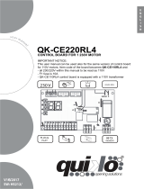
CONNECTIONS
WARNING: The control unit is designed with the automatic detection of not used N.C. inputs (Photocells, Stop and Limit
switch) except the SAFETY EDGE input. The exclude inputs in self-programming can be restored in the “Check inputs”
menu without need to repeat the programming (page 38).
Limit Switch opening M1
Limit Switch closing M1
Limit Switch opening M2
Limit Switch closing M2
Common
Motor 1
opening
Motor 1
closing
Motor 1
Neutral
Capacitor
Motor 1
Motor 2
opening
Motor 2
closing
Motor 2
Neutral
Capacitor
Motor 2
Start
Stop
Common
Antenna
START Pedestrian
Common
Photocell 1
Safety edge 1
Photocell 2
Safety edge 2
The herein reported
functions are
available starting
from revision 33, on
R1B versions only.
Optional
Obligatory jumper
without accessory
connection.
Common
Lamp
(500mA max)
AUX
(24V 800mA
max)
Rev.07 - 12/2014

67411385
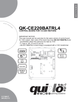
UPDOWN
ALL OTHER PARAMETERS HAVE DEFAULT SETTINGS WHICH ARE USEFUL FOR THE 90% OF THE APPLICATIONS
BUT CAN BE HOWEVER SET THROUGH THE SPECIAL MENU. FOR ENTERING INTO THE SPECIAL MENU MOVE
ON ONE OF THE MENU AND PRESS THE UP AND DOWN BUTTONS AT THE SAME TIME FOR 5 S.
26
MENU
SEA
SET
MENU
SEA
SET
MENU
SEA
SET
MENU
SEA
SET
MENU
SEA
SET
MENU
SEA
SET
MENU
SEA
SET
MENU
SEA
SET
MENU
SEA
SET
MENU
SEA
SET
MENU
SEA
SET
OK
1
2
3
4
5
6
7
8
OK
OK
OK
OK
OK OK
OK OK
OK OK
OK OK
OK OK
UP
UP
UP
UP
UP
UP
UP
OK
PRESS
BUTTON
STORED
TRANSMITTERS
START
MOTOR
ONE SINGLE
LEAF
LOGIC
PAUSE TIME
START IN
PAUSE
PROGRAM-
MING
TEST START
MENU
SEA
SET
MENU
SEA
SET
OK
UP
LANGUAGE
ITALIANO
UP
PROGRAMMING
BUTTONS
OK
DOWNUP
9
Skip this step if you do not want to program a transmitter
Press the
button of the
TX to be
stored
OK to exit
Menu or press
the button of
the next TX to
be stored
Choose the type of
motor with
UP or DOWN
To confirm and return
to main menu
With UP or DOWN
choose
the desired logic
To confirm and return
to main menu
With UP or DOWN
choose a delay for
automatic closing
To confirm and return
to main menu
Skip this step
if you want to work
in half-automatic
logic
With UP or DOWN
Choose ON
To confirm and return
to main menu
With UP or DOWN choose ON
to start times learning
At the end of the selflearning
the control unit returns automatically
to the main menu
With
UP or DOWN Choose
ON to start test
To confirm and return to
main menu
Skip this step if a TX has already been stored
With UP or DOWN choose
ON only if in single
leaf mode (Motor 1)
To confirm and return
to the main menu
Skip this step if you are working in double leaf mode
English
GATE 2 DG R1
Sistemi Elettronici
di Apertura Porte e Cancelli
International registered trademark n. 804888
®
MENU
SEA
SET
RECEIVER
MISSING
If on the display
appears the item:
Check if a receiver has
been connceted
(see page 24)
(See
page 27)
The gate will execute a CLOSING-OPENING-CLOSING CYCLE
(See
page 27)
PROGRAMMING
QUICK START
Rev.07 - 12/2014

67411385
27
MENU
Default
1 - langvage
4 - one s ngle
leaf *
SET
espanol
engl sk
fran(a s
tal ano
stop
start
off
on
off
1 240
Start
Stop
start
off
off
tal ano
kydravli(
E(kan (
U
Sliding
Reversible sliding gate
Hydraulic
Mechanic
off
7 - start n pavse
on
Off on
off
off
vnlo(k
Storing of a command
for unlocking an
electric brake
MENU FUNCTIONS TABLE GATE 2 DG R1
Description
Set value
Italian
English
French
Spanish
U
2 - trans tters
External odvle
U
Pedestr an Start
(Lear e ory
UU
Delete a trans itter
U
Ped Start.
External module
Pedestrian Start
Delete single transmitter
Delete transmitter memory
3 - otor
U
Sl d ng
Reuers ble Sl d ng gate
E(kan (
U
Disabled
In ON activates single leaf
mode (Motor 1)
5 - log (
Avto at (
U
open-stop-(lose-stop-open
2 bvttons
safety
Dead an
U
open-stop-(lose-open
Automatic
Step by step type 1
Step by step type 2
Two buttons
Safety
Dead man
Avto at (
U
6 - paVse t e
U
Setting from 1s to 4min.
OFF
(semi-automatic logics)
8 - progra ng
U U
Times learning start
In pause start is not acceped
In pause start is accepted
Note 1: The * indicates that the default value or the menu may change depending on the selected motor
type.
dut(k
Olandese
English
GATE 2 DG R1
Sistemi Elettronici
di Apertura Porte e Cancelli
International registered trademark n. 804888
®
(See page 29)
Off on
off
9 - test start
end
Start command
Select END and press OK to exit the menu.The menu
deactivates automatically after 2 minutes
(See page 28)
Rev.07 - 12/2014

The control unit is pre-set with the default settings, to start the control unit with the
DEFAULT settings just keep pressed the UP and DOWN buttons at the same time power
supplying the control unit the display shows the message init.
The DEFAULT settings are shown in the Menues table.
SELFLEARNING OPERATION TIME WITH AMPEROMETRIC SENSOR
(For electromechanical motors only)
The times learning can be done only on electromechanical gates, taking advantage of the automatic detection of
the stops.
Once the programming has been started just make sure that the gate executes the following cycle: CLOSING M2
- CLOSING M1 - OPENING M1 - OPENING M2 - CLOSING M2 - CLOSING M1.
Note: For stop detection sensitivity setting refer to the special menu.
LEARNING WITH LIMIT SWITCH
When limit switches are mounted, the gate executes automatically the follwing cycle: CLOSING M2 - CLOSING M1 -
OPENING M1 - OPENING M2 - CLOSING M2 - CLOSING M1.
Before starting the learning, make sure( through the test menu), that the relative limit switches of every leaf and every
opening are employed.
Exe: For the M2 motor closing the limit switch M2 in closing must be employed.
67411385
WORKING TIMES SELFLEARNING THROUGH IMPULSES
ATTENTION: This procedure is potentially dangerous and should only be performed by qualified people in
safety conditions.
NOTE: The card is preset with the standard working times, therefore the automation can be started even
without the times programming, simply by adjusting the timing on the display (see default times).
1) Turn off electricity, release the motors and manually position the leaves on halfway.
Reset the mechanical lock.
2) Connect the control board to the power supply
3) Select on the on-board display or JOLLY programmer, the type of motor that you are using as indicated in the
dispaly management ( E(kani( - Ele(trokydravli(, etc).
4) If necessary also set the operation logic and the other parameters. If you want to program with a transmitter, store
a transmitter before programming.
5) Select PROGra ing on the display, press OK and than one of the UP or DOWN buttons.
(If the motor starts in opening, remove and re-put power supply, select on the display reuerse otor. And through
the UP and DOWN button put it on ON, or if you have the Jolly programmer, activate the motor exchange function. )
6) At this point the gate will start the following cycle: CLOSING M2 - CLOSING M1 - OPENING M1 - OPENING M2 -
CLOSING M2 - CLOSING M1. During cycle, to store the respective stops, press UP or DOWN or START at every
point of stop of the leaf.
7) The self-learning is done.
U
UU
U
English
GATE 2 DG R1
Sistemi Elettronici
di Apertura Porte e Cancelli
International registered trademark n. 804888
®
WORKING TIMES SELF LEARNING
28
SELFLERNING OPERATION TIME WITH ENCODER / POTENTIOMETER
When an encoder is installed, it is necessary to select On in the EN(oder menu, when the potentiometer is installed, it
is necessary to select POTENtio eter in the EN(oder menu. Start programming and make sure that leaf 2 starts as
first in closing. The gate will automatically execute the following cycle: CLOSING M2 - CLOSING M1 - OPENING M1
- OPENING M2 - CLOSING M2 - CLOSING M1.
Note: For stop detection sensitivity setting refer to the special menu.
U
Rev.07 - 12/2014

FUNCTION LOGIC
AUTOMATIC LOGIC
A start impulse opens the gate. A second impluse during the opening will not be accepted.
A start impulse during closing reverses the movement.
SECURITY LOGIC
A start impulse opens the gate. A second impulse during opening reverses the movement.
A start impulse during closing reverses the movement.
STEP BY STEP TYPE 1 LOGIC
The start impulse follows the OPEN-STOP-CLOSE-STOP-OPEN logic.
STEP BY STEP TYPE 2 LOGIC
The start impulse follows the OPEN-STOP-CLOSE -OPEN logic.
DEAD MAN LOGIC
The gate opens as long as the START button of opening is pressed; releasing it the gate stops. The gate closes as
long as the button connected to the PEDESTRIAN START is pressed; releasing it the gate stops. To execute
complete opening and/or closing cycles the related pushbuttons must be constantly pressed.
2 PUSHBUTTONS LOGIC
One start opens, one pedestrian start closes. In opening the closing will not be accepted. In closing a start command
reopens, a pedestrian start command (closes) will be ignored.
NOTE 1: To have the automatic closing it is necessary to set a pause time, otherwise all the logic will be semi-
automatic.
NOTE2: It is possible to choose, whether to accept or not, the start in pause, selecting in the MENU the item
Startin pavse and choosing ON or OFF. By default, the parameter is OFF.
English
GATE 2 DG R1
Sistemi Elettronici
di Apertura Porte e Cancelli
International registered trademark n. 804888
®
67411385
29
Rev.07 - 12/2014

67411385
30
PRESS AT THE SAME TIME FOR 5 SECONDS TO ENTER OR TO EXIT THE SPECIAL MENU
MENU SP
Default
SET
10 100
10 100
0.0 5.0
Pre-flashing only
active before closing
75
Off
75
10 100
10 100
75
75
Off 6
2,5
1,5
Off 20
6 - leaf delay n (los ng *
7 - Pvshouer *
Off
Only (los ng
Off
8 - pvsk ng stroke
Off 3
Off 50
20
Off 50
20
Off 50
20
Off 50
20
bvzzer
Buzzer
15 - reuerse otor *
U
Off
On
Off
Off
UPDOWN
SPECIAL MENU FUNCTIONS TABLE GATE 2 DG R1
UP and DOWN
press END or
UP and DOWN
For entering into the special menu move on one of the menu and press the
buttons at the same time for 5 s. For exiting the special menu move on one of the
menu and press the buttons at the same time for 5 s.
Description
Set value
1 - open ng torq 1 *
2 - (los ng torq 1 *
3 - open ng torq 2 *
4 - (los ng torq 2 *
M1 opening torque
Note: with hydraulic motors
the torque will be on 100%
M2 opening torque
Note: with hydraulic motors
the torque will be on 100%
M2 closing torque
Note: with hydraulic motors
the torque will be on 100%
M1 closing torque
Note: with hydraulic motors
the torque will be on 100%
5 - leaf delay n open ng *
Setting from OFF to
6 seconds
Setting from OFF to
20 seconds
Open ng and (los ng
Only open ng
Disabled
Opening an closing
Opening only
Closing only
From OFF to 3 seconds
10 - (los ng sloudoun 1
9 - open ng sloudoun 1
12 - (los ng sloudoun 2 *
11 - open ng sloudoun 2 *
From OFF to 50% of
the stroke
From OFF to 50% of
the stroke
From OFF to 50% of
the stroke
From OFF to 50% of
the stroke
13 - preflasx ng
14 - flasx ng l gxt
Only (los ng
Nor al
U
L gxt
aluays
Normal
Control lamp
Always ON
Pre-flashing time
Synchronized right motor
Synchronized left motor
Nor al
U
English
GATE 2 DG R1
Sistemi Elettronici
di Apertura Porte e Cancelli
International registered trademark n. 804888
®
SPECIAL MENU
Rev.07 - 12/2014

MENU SP
Default
SET
Description
Set value
English
GATE 2 DG R1
Sistemi Elettronici
di Apertura Porte e Cancelli
International registered trademark n. 804888
®
OFF
ON
Off
Off
16 - EN(ODER *
xxx.s
Xxx.
xxx.s
Xxx.
16 - EN(ODER *
17 - opening ti e
otor 1
u
u
18 - (losing ti e
otor 1
u
u
xxx.s
xxx.s
Xxx.
Xxx.
In ON enables the
Encoder.
19 - opening ti e
otor 2
u
u
20 - (losing ti e
otor 2
u
u
17 - en(oder tot.
Otor 1
u
18 - en(oder par.
Otor 1
u
19 - en(oder tot.
Otor 2
u
20 - en(oder par.
Otor 2
u
In OFF disabled the
Encoder
Indicates the working times selflearning
in opening and closing on motor 1.
With UP or DOWN it is possible to increase
or reduce the working times.
Indicates the working times selflearning
in opening and closing on motor 2.
With UP or DOWN it is possible to increase
or reduce the working times.
Encoder impulses stored in programming
on motor 1.
Encoder impulses during operation
on motor 1.
Encoder impulses stored in programming
on motor 2.
Encoder impulses during operation
on motor 2.
67411385
31
Off
16 - EN(ODER *
Enables the reading of
the potentiometer with
LE card.
Potentio eter
u
Reports the current posi-
tion of the potentiometer
on the leaf of motor 1.
This parameter is useful
for seeing if the potentio-
meter is read correctly.
--------
Reports the impulses
stored by the control unit
when the leaf of motor 1
is fully open.
--------
--------
--------
--------
--------
Reports the impulses
stored by the control unit
when the leaf of motor 1
is fully close.
Reports the current posi-
tion of the potentiometer
on the leaf of motor 2.
This parameter is useful
for seeing if the potentio-
meter is read correctly.
Reports the impulses
stored by the control unit
when the leaf of motor 2
is fully open.
Reports the impulses
stored by the control unit
when the leaf of motor 2
is fully close.
21 - i.par. 1 *
u
22 - i.ap. 1 *
u
23 - i.(h. 1 *
u
24 - i.par. 2 *
u
25 - i.ap. 2 *
u
26 - i.(h. 2 *
u
Rev.07 - 12/2014

MENU SP
Default
SET
Description
Set value
English
GATE 2 DG R1
Sistemi Elettronici
di Apertura Porte e Cancelli
International registered trademark n. 804888
®
1 240
20
Off on
Off
5 100
100
0 10e9 0
1 240
100 10e4
0 100
100%
10e4
= start
Off
= start
27 - (ourtesy l gxt
N (y(le
Courtesy light setting
from 1s to 4min.
Courtesy light in cycle
28 - traff ( l gxt
reseruat on
When setting this function
the pedestrian input will be
activated to work on the
auxiliary board SEM
(traffic light management).
29 - pedestr an open ng
Setting from 5 to 100
30 - pedestr an PAvSE
31 - a((elerat on
32 - a ntenan(e (y(les
U
33 - perfor ed (y(les
U
Pause in pedestrian
opening same as in
total opening
Disabled
Acceleration ramp
Setting from 1s to 4 min.
Setting from 100 to
100000
Reports the executed
cycles. Keep pressed OK
to reset the cycles
34 - t er
U
off
off
ON PXOTO2
Disabled
Timer function active
on photocell 2
ON PEDESTR AN ENTRY
Timer function active on
pedestrian input
Active in opening
and closing
35 - EDGE1
ONLY (LOS NG
OPEN NG AND (LOS NG
ONLY OPEN NG
Active only in opening
Active only in closing
OPEN NG
AND
(LOS NG
36 - EDGE2
37 - EDGE1
8x2
38 - EDGE2
8x2
ONLY (LOS NG
OPEN NG AND (LOS NG
ONLY OPEN NG
Active in opening
and closing
Active only in opening
Active only in closing
OPEN NG
AND
(LOS NG
Nor al
U
Nor al
U
Edge is active and
protected by a 8k2 resistor
Normal N.C. contact
Edge is active and
protected by a 8k2 resistor
Normal N.C. contact
Nor al
U
Nor al
U
Rev.07 - 12/2014 67411385
32

stop
39 - PKOTO1
40 - PKOTO2
MENU SP
Default
SET
Description
Set value
OPEN NG AND (LOS NG
(LOS NG
Stop AND (LOSE
(LOSE
PAUSE RELOAD
Active in opening
and closing
Photocell active in closing
Photocell active before
opening
The photocell gives a
command to close during
opening, pause and
closing
The photocell charging the
pausing time
The photocell stops in closing
and closes when released
stop
OPEN NG AND (LOS NG
(LOS NG
Stop AND (LOSE
(LOSE
PAUSE RELOAD
Active in opening
and closing
Photocell active in closing
Photocell active before
opening
The photocell gives a
command to close during
opening, pause and
closing
The photocell charging the
pausing time
The photocell stops in closing
and closes when released
(LOS NG
OPEN NG
If the photocell is occupied
during opening, pause or
closing, the gate reopens
completely and closes
without observing the
pause time.
Delay pause ti e
u
English
GATE 2 DG R1
Sistemi Elettronici
di Apertura Porte e Cancelli
International registered trademark n. 804888
®
Delay pause ti e
u
If the photocell is occupied
during opening, pause or
closing, the gate reopens
completely and closes
without observing the
pause time.
67411385
41 - 24u avx
ALUAYS
N (Y(LE
N pavsE
OPEN NG
(LOS NG
AUX output always
power supplied
AUX output power
supplied only during opening
AUX output power
supplied only during closing
AUX output power
supplied only during pause
AUX output active only
during cycle
POS T UE BRAKE
ANAGE ENT
UU
NEGAT UE BRAKE
ANAGE ENT
U
U
Positive Electrobrake
Negative Electrobrake
ALUAYS
1 flash per sec. in opening
2 flashes per sec. in closing
Steady lit in Stop or Open.
Gate open uorning
light
Rev.07 - 12/2014
33

0 20
1
42 - opening POSiTiON
RE(OUERY *
Recovers the motor inertia
in opening after stop or
inversion.
0.1
44 - OTOR RELEASE *
U
Off
0.1 3.0
45 - BRAKE *
----
Disabled
Setting from 1 to 3
Adjusts the braking on the
limit switches
0
MENU SP
Default
SET
Description
Set value
off 8
46 - PER OD (AL pvshouer *
off
Off
Off
3
Off 5
49 - lock
off
Off
On
51 - ant ouerlap *
Off
On
Desactivate the leaves
anti-overlapping control,
allowing separate control
of the two leaves.
Activate the leaves
anti-overlapping control
off
Allows the repetition of the
Pushover functionat a
distance of time adjustable
from 0 to 8 hours at hourly
intervals
47 - ant ntrvs on
ONLY (LOS NG
ONLY OPEN NG
OPEN NG AND (LOS NG
Only on limit switch in opening
Only on limit switch in closing
On limit switches in closing
and in opening
If the limit switch is freed
manually it forces the
reclosing of the gate
48 - LOCK T E
U
Sets the lock release
time from 0 to 5 s
ONLY (LOS NG
ONLY OPEN NG
OPEN NG AND (LOS NG
Active only before opening
Active before opening
and closing
Active only before cloning
OPEN NG
The flashing light remains
ON with active timer and
open gate
The flashing light remains
OFF with the active timer
and open gate
50 - FLASX NG L GXT AND
t er
U
English
GATE 2 DG R1
Sistemi Elettronici
di Apertura Porte e Cancelli
International registered trademark n. 804888
®
67411385
0 20
1
43 - (losing POSiTiON
RE(OUERY *
Recovers the motor inertia
in closing after stop or
inversion.
1 10
Shows last event
(See alarms table)
52 - diagnosti(S
53 - sloudoun ra p torq
U
100
Adjusts the transition
between max. torque
and slowdown
0 %
100%
Rev.07 - 12/2014
34

55 - edge AVTOTEST
edge1
edge2
edge1-2
Off
edge1-2
Test enabled on edge
1 and 2
Test enabled on edge 1
Test enabled on edge 2
Disabled
MENU SP
Default
SET
Description
Set value
0
0 100
0
0 100
Adjust the tolerance
between stop and
obstacle Motor 1 opening.
0
0 100
0
0 100
off
off
off
off
off
64 - slou doun
sens t u ty *
56 - OPEN NG TOLERAN(E
otor1
U
57 - (los ng TOLERAN(E
otor1
U
58 - OPEN NG TOLERAN(E
otor2 *
U
59 - (los ng TOLERAN(E
otor2 *
U
60 - open ng sens t u ty
otor1
U
61 - (los ng sens t u ty
otor1
U
62 - open ng sens t u ty
otor2 *
U
63 - (los ng sens t u ty
otor2 *
U
Disabled
Adjusts the intervention time
of the Encoder / Potentiometer
on Motor 1 in opening
Disabled
Disabled
Adjusts the amperometric
sensitivity in slowdown.
Active only if the motors
are electromechanical.
Disabled
Adjust the tolerance
between stop and
obstacle Motor 2 opening.
Adjust the tolerance
between stop and
obstacle Motor 1 closing.
Adjust the tolerance
between stop and
obstacle Motor 2 closing.
English
GATE 2 DG R1
Sistemi Elettronici
di Apertura Porte e Cancelli
International registered trademark n. 804888
®
54 - fototest
photo1
photo2
photo1-2
Off
Off
Auto-test active only on
Photo1
Auto-test active only on
Photo2
Auto-test active on
Photo1 and Photo2
Disabled
67411385
10% (max) 99% (min)
Off (Intervention excluded)
10% (Fast intervention)
99% (Slow intervention)
10% (Fast intervention)
99% (Slow intervention)
10% (Fast intervention)
99% (Slow intervention)
Off (Intervention excluded)
Off (Intervention excluded)
off
Disabled
Off (Intervention excluded)
10% (Fast intervention)
99% (Slow intervention)
Adjusts the intervention time
of the Encoder / Potentiometer
on Motor 1 in closing
Adjusts the intervention time
of the Encoder / Potentiometer
on Motor 2 in opening
Adjusts the intervention time
of the Encoder / Potentiometer
on Motor 2 in closing
Rev.07 - 12/2014
35

MENU SP
Default
SET
Description
Set value
English
GATE 2 DG R1
Sistemi Elettronici
di Apertura Porte e Cancelli
International registered trademark n. 804888
®
Avto at (
U
Limit switch in automatic
recognition
Only limit switch in
opening present
ONLY (LOS NG
Avto at (
U
73 - sELE(T L T SU T(K
U
ONLY OPEN NG
Only limit switch in
closing present
To be activated if there is
a limit switch that stops
the motor phase.
75 - passuord
---- ----
Allows the entering of a
password blocking the
control unit parameters
modification.
END
Select END and press OK to exit the special menu.
The special menu switches off automatically after 20 minutes.
Otor internal
U
If limit switches are present
it adds an extra time to the
movement of the motors
after the reading of the limit
switches.
74 - ektra ti e
U
0.0 s 10 s
0.0 s
67411385
69 - pot. Slovdoun
threshold opening1 *
Adjust the threshold of the
potentiometer in slowdown.
By default this value is set
on 1 and can be increased
manually up to the
maximum value read on
the DEBUG VPI, VP2
menu.
65 - pot. threshold
opening 1 *
Adjusts the threshold of the
potentiometer intervention.
The parameter self-
determines in learning but
can also be adjusted later.
The lower the value, the
slower will be the response
of the potentiometer.
The parameter can be set
as maximum threshold at
the value read on the
DEBUG VPI, VP2 menu.
66 - pot. threshold
(losing 1 *
1 100
1 10
67 - pot. threshold
opening 2 *
68 - pot. threshold
(losing 2 *
70 - pot. Slovdoun
threshold (losing1 *
71 - pot. Slovdoun
threshold opening 2 *
72 - pot. Slovdoun
threshold (losing 2 *
Note 1: The * indicates that the default value or the menu may change depending on the selected motor type.
Note 2: After initialization the parameters "motor type" and "limit switch type" remain son the value chosen in the
setup program.
Rev.07 - 12/2014
36

English
GATE 2 DG R1
Sistemi Elettronici
di Apertura Porte e Cancelli
International registered trademark n. 804888
®
PASSWORD ENTERING MANAGEMENT
With a new control unit all menus can be displayed and set and the password will be disabled.
Selecting one of the Menus and keeping UP and DOWN pressed at the same time for 5 seconds, you will access the SP Menu
containing the Passuord Submenu.
Pressing OK in the Passuord Menu, you will proceed with the entering of the numeric code of the 4-digit PASSWORD.
Use UP and DOWN to increase or decrease the number, press OK to confirm it and you will pass automatically to the entering of
the next number. Pressing OK after the last entered number the word SvRE? appears, confirm the activation of the PASSWORD
and the message Ok appears, pressing UP or DOWN instead you can cancel the operation and NO OPERATION will appear on the
display.
Once entered the PASSWORD, it will be definitively activated, once the display switch off timeout has expired, or by turning off
and on again the control unit. Once the PASSWORD has been activated, the menus of the display can be only displayed but not
set. To unlock them you must enter the correct PASSWORD in the Passuord menu, if the password is wrong the message ERRor
will appear.
At this point, if the password has been entered correctly, the menus will be unlocked and it will be possible to change the
parameters of the control unit again.
If the control unit has been unlocked through Passuord Menu, it is possible to enter a new and different password, using the
same entering process as for the first one; at this point, the old password will no longer be valid.
If the password has been forgotten, the only way to unlock the control unit is to contact the SEA technical assistance, which will
assess whether to provide the procedure to unlock the control unit or not.
Note: The password cannot be set through the Jolly or Jolly 2 terminal.
POTENTIOMETER MANAGEMENT (Position Gate)
(Available only on GATE 2 DG R1B)
1 2
ON
CN1
CNP
DS1
POTENC
M2
M1
1 2 4
P01 D1 P11 P02 D2 P12 I1
5 6 7
I2
GND
I3 I4
3 8 9 10 11
+ -
LE CARD
Potentiometer 1 (Position Gate)
Potentiometer 2 (Position Gate)
D2 (White)
P02 (Green)
P12 (Brown)
D1 (White)
P01 (Green)
P11 (Brown)
To connect the potentiometer you must use the LE card (Cod.23001256) and set with Dip Switches 1 and 2 both in OFF.
With the potentiometer it is possible to access the hidden DEBUG menu to check the maximum settable value as threshold in
normal and slowdown speed.
To access this menu you have to press, in the menu that displays the firmware version, UP and OK at the same time until the
menus VP1 speed of potentiometer 1 and VP2 speed of potentiometer 2 will appear.
To view the speed of the potentiometer on the related menu, press OK.
To exit the DEBUG menu go to END and press OK.
If the reading of the potentiometer is reversed relative to the movement of the motor, on the display will appear the alarm
"Potentiometer direction" and you will have to reverse the brown wire with the green one and repeat programming.
Rev.07 - 12/2014 67411385
37

67411385
MENU
SEA
SET
---
----
----
DISPLAY INPUT STATUS
When the segment is
ON during self-
learning, the input
status is closed or
OFF.
Start
Start
pedestrian
Stop
Limit
Switch
opening
motor 1
Photocell 1
Photocell 2
Edge 1 Edge 2
Limit
Switch
closing
motor 1
Limit Switch
opening motor 2
Limit Switch
closing motor 2
Initial system
Software Version
Programming example
u.022
UP
OK
UP
UP
UP
DOWN
DOWN
DOWN
OK
OK
OK
DOWN
ELE(T
otOR
U
E(ka
U
Sl d
The settings of the control unit are made through the UP, DOWN and OK buttons. The UP and DOWN buttons to scroll through the MENUS and
SUBMENUS. By pressing OK you enter from MENU into SUBMENU and confirm the choice.
Moving in the language menu pressing the UP and DOWN buttons at the same time you access the SP MENU for special settings.
Moving in the language menu pressing the OK button for 5 seconds, you enter the CHECK MENU, where you can check the operating status of
all inputs.
L T SU T(H
(LOS NG 1
U
L T SU T(H
OPEN NG 1
U
MENU
start
Description
Description
EDGE1
PHOTO1
PHOTO2
PedESTR AN Start
END
Start test
Stop test
Pedestrian
start test
Safety edge1
test
Photocell 1
test
Photocell 2
test
M1 Opening
limit switch
test
M1 Closing
limit switch
test
The contact must be a N.O. Contact . When activating the related command
on the display SET lights up, the input works.
If SET is always on, check the wirings.
The contact must be a N.C. Contact. When activating the related command
on the display SET lights up, the input works.
If SET is always on, make sure that the contact is a N.C. Contact
The contact must be a N.C. Contact. When activating the related command
on the display SET lights up, the input works. If SET is always on, make
sure that the contact is a N.C. contact or that the related limit switch is not occupied.
The contact must be a N.O. Contact. When activating the related command
on the display SET lights up, the input works.
If SET is always on, check the wirings.
The contact must be a N.C. Contact. When activating the related command
on the display SET lights up, the input works.
If SET is always on, make sure that the contact is a N.C. Contact
IThe contact must be a N.C. Contact. When activating the related command
on the display SET lights up, the input works.
If SET is always on, make sure that the contact is a N.C. Contact
The contact must be a N.C. Contact. When activating the related command
on the display SET lights up, the input works.
If SET is always on, make sure that the contact is a N.C. Contact
The contact must be a N.C. Contact. When activating the related command
on the display SET lights up, the input works. If SET is always on, make
sure that the contact is a N.C. Contact or that the related limit switch is not occupied.
Exit menu
stop
OK
OK
OK
MENU FUNCTION TABLE CHECK GATE 2 DG R1 INPUTS
To access the Menu for input check keep pressed OK for about 5 seconds.
enabled
blo(ked
enabled
blo(ked
enabled
blo(ked
OK
enabled
blo(ked
EDGE2
Safety edge2
test
The contact must be a N.C. Contact. When activating the related command
on the display SET lights up, the input works.
If SET is always on, make sure that the contact is a N.C. Contact
OK
enabled
blo(ked
L T SU T(H
(LOS NG 2
U
L T SU T(H
OPEN NG 2
U
M2 Opening
limit switch
test
M2 Closing
limit switch
test
The contact must be a N.C. Contact. When activating the related command
on the display SET lights up, the input works. If SET is always on, make
sure that the contact is a N.C. contact or that the related limit switch is not occupied.
The contact must be a N.C. Contact. When activating the related command
on the display SET lights up, the input works. If SET is always on, make
sure that the contact is a N.C. Contact or that the related limit switch is not occupied.
Note: If the Stop, Photocell 1 and Photocell 2, Edge 1 and Enge 2 contacts are not bridged in self-learning, they will be deactivated and
can be reactivated through this menu, without repeating times self-learning.
English
GATE 2 DG R1
Sistemi Elettronici
di Apertura Porte e Cancelli
International registered trademark n. 804888
®
MENU FOR INPUT CHECK
38
Rev.07 - 12/2014

67411385
39
English
GATE 2 DG R1
Sistemi Elettronici
di Apertura Porte e Cancelli
International registered trademark n. 804888
®
RADIO TRANSMITTER SELF LEARNING
WITH RECEIVER ON BOARD OF CONTROL UNIT
!!
ROLLING CODE:
press twice
1 2 3 4
0
1
2
3
4
5
TABLE EXAMPLE
Transmitter
button
Memory
location
Serial number Customer
WARNING: Make the radio transmitters programming before you connect the antenna and insert the receiver into the
special CMR connector (if available) with turned off control unit.
With RF UNI module it will be possible to use both Coccinella Roll Plus transmitters, max. 800 codes (buttons), and radio
transmitters with fixed code, max. 100 codes (buttons). The first memorized radio transmitter will determine the type of the
remaining radio transmitters.
If the receiver is a Rolling Code, press twice the button of the radio transmitter that you want to program to memorize the first TX.
Notes:
- Enter radio transmitters learning only when the working cycle stops and the gate is closed.
- You can store max. 2 of the available 4 functions. If the control unit receives a code which was already associated to another function it will be
updated with the new function.
In the case of transmitters with fixed code it is necessary to press 1 time the button of the transmitter you want to program to store the first
remote control
FIXED CODE:
press once
MENU
SEA
SET
MENU
SEA
SET
MENU
SEA
SET
UP
MENU
SEA
SET
MENU
SEA
SET
MENU
SEA
SET
MENU
SEA
SET
UP
MENU
SEA
SET
MENU
SEA
SET
UP
MENU
SEA
SET
MENU
SEA
SET
MENU
SEA
SET
UP
MENU
SEA
SET
MENU
SEA
SET
UP
MENU
SEA
MENU
SEA
SET
MENU
SEA
SET
MENU
SEA
SET
SET
START
PEDESTRIAN
START
EXTERNAL
MODULE
STOP
DELETE A
TRANSMITTER
0
OK? OK
CLEAR
MEMORY
OK
PRESS
BUTTON
STORED
STORED
STORED
STORED
PRESS
BUTTON
PRESS
BUTTON
PRESS
BUTTON
If you want to program
the pedestrian
start as second
channel.
If you want to
delete a single
transmitter.
If you want to delete
the whole memory
If you want to program
the activation
of the LIGHT
output
as second channel.
Press the
button of the
transmitter
to be stored
Press the
button of the
transmitter
to be stored
Press the
button of the
transmitter
to be stored
Select with
UP or DOWN
the memory
location
to be deleted
and press OK
Press the
button of the
transmitter
to be stored
If you do not want to execute the cancellation,
press UP or DOWN to return to the
TRANSMITTER menu.
Confirm the cancellation.
If you want to
program the
UNLOCH as
second channel.
MENU
SEA
SET
MENU
SEA
SET
UP
MENU
SEA
SET
UNLOCH
STORED
PRESS
BUTTON
Press the
button of the
transmitter
to be stored
If you want to
program the
STOP as
second channel.
OK
OK
OK
OK
OK
OK
OK
for 10 s.
MENU
SEA
SET
OK
TRANSMITTERS
OK
Rev.07 - 12/2014

Photocell 1 and Photocell 2 Connections
Note: If the photocells are not connected, it is not necessary put a jumper between the clamps
(6 and 7 and/ou 6 and 8 of the CN1 terminal)
24VA = AUX 24V (Accessories) 800 mA max COM = 0V PH1 = Photocell contact 1
PH2 = Photocell contact 2
Note: For the autotest in the fototest menu select the photocell or the photocells on which you want
to perform it. Auto-test is possible only when the transmitter of the photocell is powered on 24V~.
The default setting of the photocell 1 is FOTO CLOSE and the one of the photocell 2 is FOTO OPEN.
The photocell 2 can also be set as TIMER (see TIMER function).
TIMER
Options AUX 24V 800 mA max can be set with on-board
Display or with Jolly device.
It is possible to chose when having tension on the AUX output.
The options are: always, only during opening, only during
cycle, only before opening or only during pause or for the
management of the positive or negative electrobrake.
N.B: For the autotest connect
the transmitters to the
contacts 20 and 21, if you do
not want the autotest connect
the transmitters to the
contacts 19 and 20.
67411385
START - STOP - PEDESTRIAN START - ANTENNA -
PHOTOCELL
PEDESTRIAN START (N.O.) The pedestrian start can be connected
between the conectors 2 and 4 of the CN1 terminal .
This input allows a partial opening, the opening space can be set through
the on-board display or through the JOLLY device.
Note1: The contact for partial opening is a N.O. Contact (Normally open).
Holding START starts the TIMER function, releasing the pedestrian start,
the operator repeats the pause and then performs the closing. In the case
of triggering a safety device the timer will automatically reset after 6
seconds.
Note2:In 2 BUTTONS logic it is necessary to keep pressed the Start Ped.
to re-close the automation.
Note3: In deadman logic this button executes the re-closing if you keep it
pressed.
Note4: When closed during pause, the gate will reclose only after this
input has been reopened.
TIMER activation: This input can be transformed into TIMER (See
TIMER).
START (N.O.) The
An impulse given to this contact opens and closes the automation depending on the selected logic, it can be given by a keyswitch, a keypad, etc.
To connect the other devices refer to the related instructions leaflets. (ie. loop detectors and proximity switches).
Note1: In DEADMAN logic keep pressed the Start for the opening of the automation.
Note2:
START is connected between connector 2 and 3 of the CN 1 terminal.
In the case of triggering a safety device
the timer will automatically reset after 6 seconds.
Holding START starts the TIMER function, releasing the start, the operator repeats the pause and then performs the closing.
In 2 BUTTONS logic this button performs the opening.
STOP (N.C.) The STOP is connected between the clamps 2 and 5 of the CN1 terminal .
When pressing this button the motor immediately stops in any condition/position. To re-start the movement give a start command.
After a stop the motor always re-starts in closing.
Can be activated through the on-board display or through the Jolly programmer. In both cases it’s a N.O. contact which provoques the
opening of the automation keeping it open as long as it is activated. When it’s released, after having paused for the set pausing time the
gate recloses. The TIMER can be activated on the inputs FOTO2, PEDESTRIAN START or keeping busy the START input.
Note1: When activated on the pedestrian entry, the pedestrian will be OFF also on the radio transmitter.
Note2: In the event of an intervention of a security device during the timer (Stop, amperometric, Edge), a start impulse restors the
movement.
Note3: In case of no power supply with open gate and active Timer the control unit will restore its function, otherwise if during restoring of
the power supply the TIMER is not activated it will be necessary to give a start impulse for the reclosing.
10 11 12 13
1 2 3 4 5 6 7 8 9
-
3
6
5
6
4
START
PEDESTRIAN
START
STOP
C
CN2
RX1
RX2
TX1
TX2
6
7
6
8
14 15 16 17 18 19 20 21 22 23
14 15 16 17 18 19 20 21 22 23
20
21
19
20
19
20
20
21
CN2
CN1
OPTIONS ON FOTO1 and FOTO2 adjustable on on- board display or with JOLLY
terminal.
FOTO CLOSE activation ((losing): if occupied, reverses the movement in closing,
during pause it prevent the closing.
Activation repeat pause (pavse RELOAD): If occupied, during pause it recharges the
timer of pause. In closing it reverses the movement.
FOTO OPEN activation (oPEning): If activated the photocell blocks the movement as
long as it’s busy, when released the opening continues.
FOTO PARK activation (stop and (lose): in opening it is not active; in pause are
activated it commands the closing when released, otherwise it’s not active; in closing it
stops the movement as long as it is busy, when released the closing continues.
FOTO STOP activation (STOP): When activated before the opening the photocell
blocks the automation as long as it is busy, during the opening it will be ignored. In
closing the intervention of the photocell causes the reopening.
Activation PHOTO CLOSE IMMEDIATELY ((lose): The photocell stops the gate as
long as it is occupied in both opening and closing, when released it gives a closing
command (Closing one second after release of the photocell ).
Activation delay pause TI E: If the photocell is occupied during opening, pause or
closing, the gate reopens completely and closes without observing the pause time.
U
English
GATE 2 DG R1
Sistemi Elettronici
di Apertura Porte e Cancelli
International registered trademark n. 804888
®
40
Rev.07 - 12/2014

67411385
SAFETY EDGE AND FLASHING LAMP
SAFETY EDGE
Two safety edges (EDG1 e EDG2) can be connected, respectively between the contacts 9, 11 and 10 and 11 of CN1.
Pressing EDG1 and EDG2, the contact opens, causing a partial reversing of the gate in closing and opening.
Note1: Put a jumper between the not used N.C. Contacts. The EDG1 and EDG2
inputs can be set: only in closing, only in opening or in both directions.
Note2: It is possible to activate a balanced edge 8K2 through the on board
display or through the Jolly programmer, in such case the edge contact will be
controled by a specific resistance value, detecting the possible involontary short
circuit of the device. In case of an imbalanced device a special alarm will show on
the on board display or on the JOLLY programmer.
If you connect a wireless edge it is possible to make a self-test on the power
supply of the receiver by connecting it to 24Vac and selecting in the Edge
avtotest menu the edge or the edges on which to perform the test.
SAFETY GATE
The Safety Gate, unlike the amperometric sensor, can be used both on
electromechanical and hydraulic operators.
The Safety Gate is an ENCODER allowing the detection of the gate position
and its reversing in case of obstacles. To use the ENCODER it is necessary
to enable it inside the special EN(oder Menu. The sensitivity on the obstacle is
adjustable from 0 - 99%. The higher the percentage is the more it will be
difficult to detect the obstacle.
AMPEROMETRIC DEVICE FOR ELECTROMECHANICAL OPERATORS
This control unit comes with an obstacle detection system working only on electromechanical operators allowing to
have the reversing on obstacles and the automatic detection of the stops.
Sensitivity adjustable from off to 99% inside the special menu. The more the percentage is high the more the
obstacle detection will be difficult. On hydraulic unit this parameter will be always OFF.
SAFETY GATE OR AMPEROMETRIC MANAGEMENT
ATTENTION: The first
operation after power failure, will
be executed with the set speed
to search the mechanical stops
limit.
SAFETY GATE 1
1
3
4
1
3
4
SAFETY GATE 2
1
2
3 4
ENC1+24V ENC2 GND
CN7
2
24V Flashing light 3W Max
The flashing light can be connected between the FLS and COM
connectors from Cn1 (It is recomended to use a 24V Flash Led
flashing light).
It blinks once per second during opening and twice per second during
closing, while it remains lit during pause.
Throught the warning light it is also possible to identify alarm signals comming from the STOP, PHOTOCELL 1,
PHOTOCELL2 and EDGE devices. Through the on board display or the Jolly programmer it is possible to activate the pre -
flashing function and/or to modify the flashing light function choosing between fixed flashing, control lamp or Buzzer.
The pre-flashing can be set from 0 to 5 s. or it is possible to have it only before closing.
COURTESY LIGHT
Timing
from 0 to 4 min
(230V~ 50W Max - 115V~ 50W Max)
CN5
34 35
English
GATE 2 DG R1
Sistemi Elettronici
di Apertura Porte e Cancelli
International registered trademark n. 804888
®
10 11 12 13
1 2 3 4 5 6 7 8 9
CN1
9
11
10
11
13
11
FLS
Common
41
EDG2 Safety edge
in opening
EDG1 Safety edge
in closing
Rev.07 - 12/2014

Example
Motor 2
Motor 1 connection
M = Opening/Closing
Com = COMMON
Motor 1
Motor 2 connection
M = Opening /Closing
Com = COMMON
Motor to be connected in case
of single-leaf.
M1
M2
Cap M2
Cap M1
Example
POWER SUPPLY INPUT
NOTE: For power supply connection follow the rules in
force
MOTORS CONNECTION, CAPACITY AND POWER SUPPLY
CN4
Phase 1
Neutral
Phase 2
Phase 1
Neutral
Phase 2
CN3
CN4
Line
Neutral
67411385
CN3
CN6
24 25 26 27 28 29 30 31 32 33
L N
27
28
32
33
24
25
26
29
30
31
English
GATE 2 DG R1
Sistemi Elettronici
di Apertura Porte e Cancelli
International registered trademark n. 804888
®
42
Rev.07 - 12/2014
/