
CET s.r.l.
Vers. 1.0
GCM 50
Pag. 1
CET
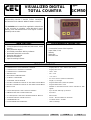
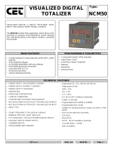
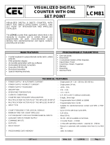
VISUALIZED DIGITAL
TOTAL COUNTER
Type:
GCM50
VISUALIZED DIGITAL 5 DIGITS TOTAL COUNTER,
WITH INPUT FOR SINGLE DIRECTIONAL COUNTS.
The GCM 50 total counter finds application where there
is the necessity to visualize, mono-directional counts
deriving from electromechanical and logical contacts,
proximity and encoder.
MAIN FEATURES
PROGRAMMABLE PARAMETERS
• Frontal keyboard in polycarbonate (antiscratch, antioil,
antacid).
• IP65 protection degree
• Accessible parameters with key software
• Removable terminals connection.
• Execution DIN 48 x 48.
• Recessed assembly.
• Special retaining brackets.
• 2 conversion factors of the impulses
• Input (Slow / Fast)
• Memory
• Reset key
• Decimal Point
TECHNICAL FEATURES
• POWER SUPPLY IN ALTERNATE CURRENT
• POWER SUPPLY IN DIRECT CURRENT
• POWER SUPPLY TOLERANCE
• ABSORPTION
• OPERATING TEMPERATURE
• CLIMATIC CONDITIONS
• TOTALIZER VISUALIZATION
• MULTIPLICATION FACTOR M1 OF THE INPULSES IN INPUT
• MULTIPLICATION FACTOR M2 OF THE INPULSES IN INPUT
• INPUT TYPE
• COUNT FREQUENCY FOR LOGICAL SIGNALS
• MINIMUM TIME FOR COUNT IMPULSES
• CUT FREQUENCY FOR ELECTROMECHANICAL INPUTS
• AUXILIARY INPUTS POWER SUPPLY
• COMMAND IMPUTS
• PROGRAMMED DATA MEMORY
: Single power 24 - 110 - 230 Vac (50 / 60 Hz).
: Single power 24 Vdc
: +10% - 15%.
: 2 W - 3 VA.
: -5 °C + 55 °C.
: U.R. 95 % at 40 °C (without condensate).
: 5 digits, 7,5 mm high
: Programmable from 0,00001 to 9,99999.
: Programmable from 1 to 99.
: Suitable for electromechanical contact and NPN or PNP
signals
: Up to 15 KHz with Duty Cycle=50%.
: 0,25 mSec.
: About 30 Hz.
: 24 Vdc – 80 mA available on terminals.
: 1 Totalizer Reset - 1 Inhibit.
: static (no battery)

CET s.r.l.
Vers. 1.0
GCM 50
Pag. 2
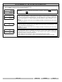
DESCRIPTION OF THE FRONTAL KEYBOARD
ø
WHITE
The key 'LEFT ARROW' in normal operating phase visualizes, blinking, all the programmings executed without the
limitation of the insertion code. The time of scansion of the programmings is given from the pressure of the same
key. It exits automatically from this phase after 5 sec of the last pressure of the same key.
In programming phase it moves the cursor of the figure towards left of a step, than at the beginning it is on the right
side first one on the. At the end it resumes from the first one to right.
ù
WHITE
The key 'UP ARROW' in normal operating phase visualizes the totalizer of impulses.
In programming phase it increases the value of the blinking figure.
ú
BLUE
The key 'PRG' pressed for 2 sec. allows to enter in the programming phase, visualizing on display C.0000.
In the programming phase, pressing key 'PRG' impulsively, it exits from the programming phase. The instrument exits
automatically from the programming phase, 60 sec. after the pressure of the last key.
û
GREEN
The key 'ENT/RES' in normal phase of counting has the 'RESET' function, with the modalities to it attributed in the
programming phase.
In programming phase it confirms and memorizes the visualized data and passes to the successive function. If it has
arrived to list end it resumes from the beginning.
INPUTS / OUTPUTS DESCRIPTION E SERIES
AC POWER SUPPLY
(inputs 1-2)
AC Power Supply Input of the instrument; it can be to 24 - 110 - 230 VAC in according to demand.
DC POWER SUPPLY
(inputs 3-4)
24 VDC Power Supply Input of the instrument; input 3 (-), input 4 (+).
12 VDC - 80mA
(inputs 12-13)
24 VDC – 80 mA auxiliary Power Supply that the instrument supply to feed the Encoder and proximity amplified.
PRI
(input 10)
Input used for the polarization of the count and command inputs : connecting the PRI output to input 13 it configures the instrument in
Negative logic (NPN), connecting the PRI output to input 12 it configures the instrument in Positive logic (PNP).
INPUT
(input 11)
Input of count adapted for electromechanical and logical contacts, encoder and 3 wires proximity amplified, configurable in Positive
(PNP) and Negative (NPN) logic through PRI input (10).
RESET
input 7)
Input of RESET that executes the reset of the visualized count showed on display at the moment of its activation.
INHIBIT
(input 8)
Input of count inhibition: when activated it blocks the count of the normal counter and the totalizer.
INPUTS / OUTPUTS DESCRIPTION Z SERIES
AC/DC POWER
SUPPLY
(inputs 2 - 10)
AC or DC Power Supply Input of the instrument; it can be to 24 - 110 - 230 VAC or 12 - 24 VDC in according to demand.
24 VDC - 80mA
(inputs 7 - 8)
12 VDC - 80 mA auxiliary Power Supply that the instrument supply to feed the Encoder and proximity amplified.
PRI
(input 9)
Input used for the polarization of the count and command inputs : connecting the PRI output to input 8 it configures the instrument in
Negative logic (NPN), connecting the PRI output to input 7 it configures the instrument in Positive logic (PNP).
INPUT
(input 5)
Input of count adapted for electromechanical and logical contacts, encoder and 3 wires proximity amplified, configurable in Positive
(PNP) and Negative (NPN) logic through PRI input (9).
RESET
(input 6)
Input of RESET that executes the reset of the visualized count showed on display at the moment of its activation.

CET s.r.l.
Vers. 1.0
GCM 50
Pag. 3
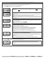
PROGRAMMING OF THE OPERATION PARAMETERS
The programmable parameters are divided in two groups and protect with a 4 figures code.
In order to approach the programming, proceed in the following way:
- Press key PRG for about 2 sec. On the display appears:
Cod
0000
GROUP 1
:
in order to approach the parameters of group 1, insert code
2357
and press
ENT
Æ1 “
©0000
5 digits multiplier , programmable from 0,1 to 9,9999.This parameter allows to convert the
number of the input impulses, showing them on the display in an other format. If it programmed
= 0 it comes reprogrammed automatically to 1. If a value lower than 1 is inserted, it obtains the
division of the impulses. Es. I want to divide by 25 the impulses in input; calculation 1 : 25 =
0.04.
Attention: the variation of the value of the multiplying modifies automatically the value of the
count and the totalizer.
Æ2 10
2 digits multiplier, programmable from 1 to 99.This parameter allows to convert the number
of the input impulses, showing them on the display in an other format. If it programmed = 0 it
comes reprogrammed automatically to 1.
Attention: the variation of the value of the multiplying modifies automatically the value of the
count and the totalizer.
1æ F
1æ 5
Input Fast - Slow.
This programming allows to predispose the input of count to read signals coming from
electromechanical contacts (relais, switches etc.) that introduces false signals, or from logical
signals like proximity, encoder, transistor etc.)
In = F. predisposes the instrument in order to read logical signals up to 15 KHz.
In = S. predisposes the instrument in order to read electromechanical contacts up to 30 Hz.

CET s.r.l.
Vers. 1.0
GCM 50
Pag. 4
PROGRAMMING OF THE OPERATION PARAMETERS
The programmable parameters are divided in two groups and protect with a 4 figures code.
In order to approach the programming, proceed in the following way:
- Press key
PRG
for about 2 sec. On the display appears:
Cod
0000
GROUP 2
:
in order to approach the parameters of group 1, insert code
2413
and press
ENT
key
NeÆon
NeÆoF
MEM. = Actived or excluded memory.
This parameter allows to program the saving of the current counter value during the power off
of the instrument.
MEM.on. = memorization of the count during the power OFF. When power ON the instrument,
the display will visualize the last present value in the power OFF phase.
MEM.of. = excluded memorization of the count; every time that the instrument comes powered
OFF and then powered ON the count comes lost and the instrument restart always from the
initial condition.
RreËon
reËoF
RES. = RESET Key ON / OFF; this programming enables and disables the RESET function of
frontal key RES during the operation of the counter. The disabling does not allow to reset the
counter and the totalizer.
RES.on = RESET function of key RES enabled
RES.of. = RESET function of key RES disabled
¼È O
¼È 4
d.P. = Programming of the Decimal Point of the Counter and the Totalizer.
This programming allows to add a decimal point to the visualization on the 5 digits, in order to
obtain counts with various resolutions.
d.p. = 0 Decimal Point excluded; visualization 99999
d.p. = 1 Decimal Point on the second display from right; visualization 9999,9
d.p. = 2 Decimal Point on the third party display from right; visualization 999,99
d.p. = 3 Decimal Point on the fourth display from right; visualization 99,999
d.p. = 4 Decimal Point on fifth display from right; visualization 9,9999
Attention, the Decimal Point is fictitious only, it doesn't realize any conversion.
¹È È
¹È ê
A.P. = Activation mode of the programmed parameters.
With this programming is possible to activate the executed programmings directly to the exit of
the programming or, when exited of the programming, after a RESET (with frontal key or from
rear input)
A.P. = P. Activation of the parameters to the exit of the programming.
A.P. = r. Activation of the parameters to the exit of the programming after a RESET.
Pressing the key ù the totalizer of impulses will be visualized for 5 sec.
Toì
99999
The totalizer visualizes all the impulses that the instrument counts from its input IN1.
It can be resetted through frontal key RES only or from RESET input when it is visualized on
the display.

CET s.r.l.
Vers. 1.0
GCM 50
Pag. 5
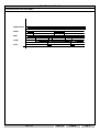
OPERATION DIAGRAMS
OPERATION WITH RESET AND INHIBIT
POWER SUPPLY
INHIBIT
INPUT
COUNT
RESET

CET s.r.l.
Vers. 1.0
GCM 50
Pag. 6
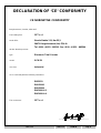
DECLARATION OF ‘CE’ CONFORMITY
CE NORMATIVE CONFORMITY
Borgolavezzaro, October, 03rd 2005
The building firm:
CET s.r.l.
Head office:
Strada Statale 211, Km 53,3
28071 Borgolavezzaro (No) ITALIA
Tel. 0039 - (0)321 - 885301 Fax. 0039 - (0)321 - 885560
declare that the products:
type :
Electronic Total Counter
model:
GCM 50
use class:
Industrial
are in conformity with the following normatives:
EN55011
ENV50141
ENV50204
EN61000-4-2
EN61000-4-4
The constructor :
CET s.r.l.
________________________________
Signature

CET s.r.l.
Vers. 1.0
GCM 50
Pag. 7
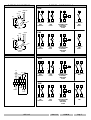
Z SERIES CONNECTIONS
Z SERIES - INPUT SIGNALS
NPN
-
+ - + - + + -
INPUT FOR INPUT FOR INPUT FOR INPUT FOR
NPN NPN PROXIMITI AND NPN
CONTACT LOGIC ENCODER RESET
AMPLIFIED
24 VDC
PNP
-
- + - + - + +
INPUT FOR INPUT FOR INPUT FOR INPUT FOR
PNP PNP PROXIMITI AND PNP
CONTACT LOGIC ENCODER RESET
AMPLIFIED
24 VDC
E SERIES CONNECTIONS
E SERIES - INPUT SIGNALS
NPN
-
+ - + - + + - -
INPUT FOR INPUT FOR INPUT FOR RESET INHIBIT
NPN NPN PROXIMITI AND NPN
CONTACT LOGIC ENCODER
AMPLIFIED
24 VDC
PNP
-
- + - + - + + +
INPUT FOR INPUT FOR INPUT FOR RESET INHIBIT
PNP PNP PROXIMITI AND PNP
CONTACT LOGIC ENCODER
AMPLIFIED
24 VDC
7
5
8
9
5
7
8
9
8
9
PROX
ENC
7
8
5
7
6
8
5
7
9
5
8
7
9
7
9
PROX
ENC
7
8
5
8
6
12
11
13
10
11
12
13
10
13
10
PROX
ENC
12
13
11
13
11
12
10
11
13
12
10
12
10
PROX
ENC
12
13
11
12
7
12
8
13
7
13
8
PRI
1
GN
D
11
2
3
4
5
6
7
8
9
10
+ 24 VDC
Reset
CNT
RL1
24 VDC
-
+
DC POWER
SUPPLY
PRI
1
GND
11
2
3
4
5
6
7
8
9
10
+ 24VDC
80mA Max
Reset
CNT
RL1
AC POWER
SUPPLY
-
+
24 VDC
INPUT
INHIBIT
7
8
9
10
11
12
13
1
2
3
4
5
6
PRI
RESET
POWER SUPPLY
AC
RL1
24 VDC
-
+

CET s.r.l.
Vers. 1.0
GCM 50
Pag. 8
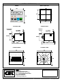
OVERALL DIMENSIONS (mm)
FRONT DRILL TEMPLATE
E SERIES SIDE Z SERIES SIDE
E SERIES REAR
Z SERIES REAR
CET
CETCET
CET
CET
CETCET
CET
s.r.l.
Strada Statale 211 Km 53,550
28071 Borgolavezzaro - NO - ITALY
Tel : ++39 0321-885180/885301/885807
Fax : ++39 0321-885560
http://www.cet-italy.com
e-mail: info@cet-italy.com
Agent:
45
45
48
48
ENT
PRG
electronic counter GCM
L1 L2
RES
CET
CETCET
CET
35952
116
93
4
19
44x44
REMOVABLE
TERMINALS
RETAINING
BRACKETS
10
1
16
93
4
12
44x44
UNDECAL
SOCCAL
RETAINING
BRACKETS
10
44
44
7 8 9 10 11 12 13
1 2 3 4 5 6
44
44
1 11
2
3
4
5
6
7
8
9
10
-
 1
1
-
 2
2
-
 3
3
-
 4
4
-
 5
5
-
 6
6
-
 7
7
-
 8
8


in altre lingue
- English: CET GCM50 Owner's manual
Documenti correlati
-
 CET NCM50 Manuale del proprietario
-
 CET GFM50 Manuale del proprietario
-
 CET GFM40 Manuale del proprietario
-
 CET LCM60 Manuale del proprietario
-
 CET LFM50 Manuale del proprietario
-
 CET LFM40AN Manuale del proprietario
-
 CET LCM81 Manuale del proprietario
-
 CET LFM52 Manuale del proprietario
-
 CET GFM41 Manuale del proprietario
-
 CET NCM52 Manuale del proprietario


