
CET - s.r.l.
Vers. 1.0
LFM 52
Pag. 1
CET
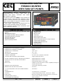
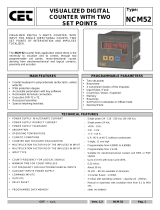
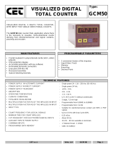
VISUALIZED DIGITAL
PERIOD COUNTER
WITH TWO SET POINTS
Type:
LFM52
PROGRAMMABLE DIGITAL VISUALIZATOR OF
ROTATIONS WITH 5 DIGITS, WITH TWO SET
POINTS AND INPUT SUITABLE FOR MONO
DIRCTIONAL COUNTING.
The period counter model LFM52 is used to display and
control, through a relay threshold, rotational or linear
speeds or counting referred to a pre selected time base.
All the common types of controls are available using five
different programmable operations.
It reads signals coming form electromechanical and
logical contacts, proximity switches and encoder.
It finds application like RPM meter, tachometer, speed
meter, productions meter etc.
GENERAL FEATURES
PROGRAMMABLE PARAMETERS
• Frontal keyboard in polycarbonate (antiscratch, antioil,
antacid).
• IP65 protection degree
• Accessible parameters with key software
• Removable terminals connection.
• Execution DIN 48 x 96.
• Recessed assembly.
• Special retaining brackets.
• Two Set Points
• Multiplier Factor
• Divisor Factor
• Time Base
• Display Reset Time
• Display Adjournment Time
• Input for Electromechanical or Logic Contacts
• Programmable Reset Key
• Programmable Decimal Point
• Operating Mode
• Input Inhibit Time
TECHNICAL FEATURES
• POWER SUPPLY IN ALTERNATE CURRENT
• POWER SUPPLY IN DIRECT CURRENT
• POWER SUPPLY TOLERANCE
• ABSORPTION
• OPERATING TEMPERATURE
• CLIMATIC CONDITIONS
• COUNTER AND TOTALIZER VISUALIZATION
• MULTIPLICATION FACTOR OF THE INPULSES IN INPUT
• DIVISOR FACTOR OF THE INPULSES IN INPUT
• TIME BASE
• INPUT TYPE
• MAXIMUM COUNT FREQUENCY
• MINIMUM TIME FOR INPULSES COUNT
• CUT OFF FREQUENCY FOR ELECTROMECHANICAL
INPUTS
• COMMAND INPUTS
• OUTPUTS
• RESET RELAY
• AUXILIARY INPUT SUPPLY
• PROGRAMMED DATA MEMORY
: 230 Vac (50 / 60 Hz).
: 24 Vdc
: +10% - 15%.
: 2 W - 3 VA.
: -5 °C + 55 °C.
: U.R. 95 % a 40 °C (without condensate).
: 5 digits, display high 14mm.
: programmable from 1 to 10000.
: programmable from 1 to 10000.
: Programmable between 1 / 60 / 3600.
: suitable for electromechanical contacts, amplified proximity and
encoder, NPN and PNP
: up to 25 KHz with Duty Cycle=50%.
: 0,25 mSec.
: about 30 Hz.
:
: 1 Counter Reset - 1 Count Inhibit.
: 2 relays with operating contacts - capacity 2A - 250Vac.
: Manual or automatic with excitation time from 0,1 to 99,9 sec.
: 24 Vdc - 80 mA available on terminals.
: Static (no battery)

CET - s.r.l.
Vers. 1.0
LFM 52
Pag. 2
DESCRIPTION OF THE FRONTAL KEYBOARD
ø
YELLOW
In programming phase it moves the cursor of the figure towards left of a step, than at the beginning it is
on the right side first one on the. At the end it resumes from the first one to right.
ù
YELLOW
The key 'UP ARROW' in normal operating phase visualizes the totalizer of impulses.
In programming phase it increases the value of the blinking figure.
ú
BLUE
The key 'PRG' pressed for 2 sec. allows to enter in the programming phase, visualizing on display
C.0000.
In the programming phase, pressing key 'PRG' impulsively, it exits from the programming phase. The
instrument exits automatically from the programming phase, 60 sec. after the pressure of the last key.
û
RED
The key 'ENT/RES' in normal phase of counting has the 'RESET' function, with the modalities to it
attributed in the programming phase.
In programming phase it confirms and memorizes the visualized data and passes to the successive
function. If it has arrived to list end it resumes from the beginning.
INPUTS / OUTPUTS DESCRIPTION
DC POWER
(input 1-2) 24V DC Power Supply of the instrument.
AC POWER
(input 3-4) 230 VAC Power Supply of the instrument.
24 VDC - 80mA
(input 5 - 6) 24 VDC - 80 mA auxiliary Power Supply that the instrument supply to feed the Encoder and amplified
proximity.
INPUT
(input 7) Input of count adapted for electromechanical and logical contacts, encoder and 3 wires proximity
amplified, configurable in Positive (PNP) and Negative (NPN) logic by the dip switches on the rear.
RESET
(input 8) Input of RESET that executes the reset visualized count showed on display at the moment of its
activation and of the relays depending on the programmed modality under code 020
INHIBIT
(input 9) Input of count inhibition: when activated it blocks the count of the normal counter and the totalizer.
RL2
(input 10 - 11) Output of Relay 2, connected to the operation of the Set Point S2. The Common and Normally Opened
contacts are available.
RL1
(input 12 - 13) Output of Relay 1, connected to the operation of the Set Point S1. The Common and Normally Opened
contacts are available.
DESCRIPTION OF THE DISPLAY AND LED’S OPERATION
LED 1 (FRONTAL) It comes activated to the reaching of the Set Points S1.
LED 2 (FRONTAL) It comes activated to the reaching of the Set Points S2.
LED 1 (REAR) It signals the presence of the input signal.
-----
When the device is switched on and when there are no impulses in its input, the device
visualize 4 horizontal bars.
Pressing the key ù the totalizer of impulses will be visualized for 5 sec.
Toì
99999
The totalizer visualizes all the impulses that the instrument counts from its input IN1.
It can be resetted through frontal key RES only or from RESET input when it is visualized on
the display
.

CET - s.r.l.
Vers. 1.0
LFM 52
Pag. 3
SET POINTS PROGRAMMATION
For SET POINT and HYSTERESIS programming access, proceed as follow:
- Press key ‘PRG’ in impulsive mode; on display appears:
5¿1<
10000
SG.1 = SET POINT 1, programmable between 0 and 99999.
5¿2<
1000
SG.2 = SET POINT 2, programmable between 0 and 99999.
Key ENT confirms the data. In order to exit the programming, press key PRG.
PROGRAMMING OF THE OPERATION PARAMETERS
The programmable parameters are divided in two groups and protect with a 4 figures code.
In order to approach the programming, proceed in the following way:
- Press key PRG for about 2 sec. On the display appears:
Cod
000
GROUP 1
:
in order to approach the parameters of group 1, insert code
101
and press
ENT
¾Æ
0001
F.M. = 4 digits multiplier , programmable from 1 to 10000. This parameter allows to multiply
the number of the input impulses, showing them on the display in an other format. If it
programmed = 0 it means programmed 10000.
Attention: the variation of the value of the multiplying modifies automatically the value of the
count and the totalizer.
¾¼
0001
F.d. = 4 digits divisor, programmable from 1 to 10000. This parameter allows to divide the
number of the input impulses, showing them on the display in an other format. If it programmed
= 0 it means programmed 10000.
Attention: the variation of the value of the multiplying modifies automatically the value of the
count and the totalizer.
ºÌ
60
b.t. = Time Base.
This programming allows to select in which time base shows on the display the measure in
input. There are three scales:
1 = Time Base: seconds, measure visualization in seconds (ex. Meters/seconds)
60 = Time Base: minutes, measure visualization in minutes (ex. Liters/minutes)
3600 = Time Base: hours, measure visualization in hours (ex. Bottles/hour)

CET - s.r.l.
Vers. 1.0
LFM 52
Pag. 4
PROGRAMMING OF THE OPERATION PARAMETERS
The programmable parameters are divided in two groups and protect with a 4 figures code.
In order to approach the programming, proceed in the following way:
- Press key
PRG
for about 2 sec. On the display appears:
Cod
000
GROUP 2
:
in order to approach the parameters of GROUP 2, insert code
020
and press
ENT
½òÇ1
E.i = Delay Time for the excitation of the Relay output1.
This parameter allows to program the delay time of the activation of the Relay output RL1. It’s
programmable between 0 (no delay) and 9,9 sec.
¼òÇ1
d.i = Delay Time for the unexcitation of the Relay output1.
This parameter allows to program the delay time of the unactivation of the Relay output RL1.
It’s programmable between 0 (no delay) and 9,9 sec.
½ïÇ1
E.ii = Delay Time for the excitation of the Relay output2.
This parameter allows to program the delay time of the activation of the Relay output RL2. It’s
programmable between 0 (no delay) and 9,9 sec.
¼ïÇ1
d.ii = Delay Time for the unexcitation of the Relay output1.
This parameter allows to program the delay time of the unactivation of the Relay output RL2.
It’s programmable between 0 (no delay) and 9,9 sec..
Ì1Ç0
t. = Reset time of the display.
This parameter allows to program the maximum time from the last impulse after that the
instrument reset the display, showing the four horizontal bars. If programmed = 0, with no
impulses in input the instrument shows the last calculated value. If the programmed time is
lower than the time between the impulses, the instrument shows the four horizontal bars.
This parameter is useful to indicate when a plant is in stop or when there are no impulses in
input or when the impulse source is damaged. It’s programmable between 0,1 (instantaneous)
and 99,9 seconds.
̼ Ç1
t.d. = Updating time of the display.
This parameter allows to program the delay time of the data adjournment on the display. It’s
programmable between 0 (instantaneous) and 9,9 sec
1æ F
1æ 5
Input Fast - Slow.
This programming allows to set the count input to read signals coming from electromechanical
contacts (relays, switches etc.) or from logical signals like proximity switches transistor and
encoder.
In = F. sets the input to read digital signals up to 28 KHz.
In = S. sets the input to read electromechanical signals up to 25 Hz.
rËoí
rËon
Operation of the RESET Key; this programming enable and disable the RESET working of
the frontal RES key during the operation, as in the following modes:
RS.ou. = executes the RESET of the visualized parameter + the Relay Output
RS.on. = executes the RESET of the visualized parameter
RS.oF. = RESET working of the RES key excluded.
RS.F.t. = executes, at the same time, the RESET of the frequencymeter, of the totalizer and
of the Relay Outputs
¼È O
¼È 5
d.P. = Programming of the Decimal Point
This programming allows to add a decimal point to the visualization on the 4 digits, in order to
obtain counts with various resolutions.
d.p. = 0 Decimal Point excluded; visualization 99999
d.p. = 1 Decimal Point on the second display from right; visualization 9999,9
d.p. = 2 Decimal Point on the third party display from right; visualization 999,99
d.p. = 3 Decimal Point on the fourth display from right; visualization 99,999
d.p. = 4 Decimal Point on the fourth display from right; visualization 9,999
d.p. = 5 Floating Point.
Á 001
I = Initial Time of inhibition of the activation of the Relay output.
This parameter allows to inhibit the activation of the relay output for the time sets. During this
time the relay output is excluded. It’s operation follows the programming in Ut. under the code
121. It’s programmable between 0 (excluded) and 999 sec.

CET - s.r.l.
Vers. 1.0
LFM 52
Pag. 5
¹È È
¹È ê
A.P. = Activation mode of the programmed parameters.
With this programming is possible to activate the executed programmings directly to the exit of
the programming or, when exited of the programming, after a RESET (with frontal key or from
rear input).
A.P. = P. Activation of the parameters to the exit of the programming.
A.P. = r. Activation of the parameters to the exit of the programming after a RESET.
PROGRAMMING OF THE OPERATION PARAMETERS
The programmable parameters are divided in two groups and protect with a 4 figures code.
In order to approach the programming, proceed in the following way:
- Press key
PRG
for about 2 sec. On the display appears:
Cod
000
GROUP 3
:
in order to approach the parameters of GROUP 3, insert code
121
and press
ENT
N¼ 0
Md. = Programming of the operation Mode
This programming allows to program the operation mode of the Set Points, of the Hysteresis
and of the Relay Outputs.
Md. = 0 Two Lower Set Points (RL1 and RL2 excited under the Set Point value)
Md. = 1 Two Upper Set Points (RL1 and RL2 excited over the Set Point value)
Md. = 2 Upper Set Point + Lower Set Point (RL1 excited Over the Set Point value and RL2
excited under the Under the Set Point value)
Md. = 3 Two Lower Set Points + maintained relay (RL1 and RL2 excited even Over the Set
Points values; they can be reset after a RESET command or switching OFF and ON
the instrument).
Md. = 4 Two Upper Set Points + maintained relay (RL1 and RL2 excited even Under the Set
Points values; they can be reset after a RESET command or switching OFF and ON
the instrument).
Md. = 5 One Upper Set Point and one Lower Set Point + maintained relay (the RL1
relay is always excited even Under the Set Point value and the RL2 relay is
always excited even Over the Set Point value . It can be reset with a RESET
command or switching OFF and ON the instrument).
UÌ 0
Ut. = Programming of the RESET Input and of the operation of the INHIBIT time.
This programming allows to select the operation of the RESET input and the operation mode
of the Inhibit time.
Ut. = 0 Reset of the visualized value + relay (with inhibit time at the starting)
Ut. = 1 Frequency Reset only + relay (with inhibit time at the starting)
Ut. = 2 Frequency Reset + totalizer (at the same time) + relay (with inhibit time at
the starting)
Ut. = 3 Reset of the visualized value + relay (with inhibit time with the first impulse)
Ut. = 4 Frequency Reset only + relay (with inhibit time with the first impulse).
Ut. = 5 Frequency Reset + totalizer (at the same time) + relay (with inhibit time with the first
impulse).

CET - s.r.l.
Vers. 1.0
LFM 52
Pag. 6
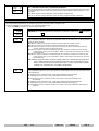
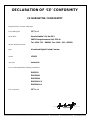
DECLARATION OF ‘CE’ CONFORMITY
CE NORMATIVE CONFORMITY
Borgolavezzaro, October, 03rd 2005
The building firm:
CET s.r.l.
Head office:
Strada Statale 211, Km 53,3
28071 Borgolavezzaro (No) ITALIA
Tel. 0039 - 321 - 885301 Fax. 0039 - 321 - 885560
declare that the products:
type :
Visualized Digital Period Counter
model:
LFM52
use class:
Industrial
are in conformity with the following normatives:
EN55011
ENV50141
ENV50204
EN61000-4-2
EN61000-4-4
The constructor :
CET s.r.l.
________________________________
Signature

CET - s.r.l.
Vers. 1.0
LFM 52
Pag. 7
Programming Notes
----------------------------------------------------------------------------------------------------------------------------------------------------------
----------------------------------------------------------------------------------------------------------------------------------------------------------
----------------------------------------------------------------------------------------------------------------------------------------------------------
----------------------------------------------------------------------------------------------------------------------------------------------------------
----------------------------------------------------------------------------------------------------------------------------------------------------------
----------------------------------------------------------------------------------------------------------------------------------------------------------
----------------------------------------------------------------------------------------------------------------------------------------------------------
----------------------------------------------------------------------------------------------------------------------------------------------------------
----------------------------------------------------------------------------------------------------------------------------------------------------------
----------------------------------------------------------------------------------------------------------------------------------------------------------
----------------------------------------------------------------------------------------------------------------------------------------------------------
----------------------------------------------------------------------------------------------------------------------------------------------------------
----------------------------------------------------------------------------------------------------------------------------------------------------------
----------------------------------------------------------------------------------------------------------------------------------------------------------
----------------------------------------------------------------------------------------------------------------------------------------------------------
----------------------------------------------------------------------------------------------------------------------------------------------------------
----------------------------------------------------------------------------------------------------------------------------------------------------------
----------------------------------------------------------------------------------------------------------------------------------------------------------
----------------------------------------------------------------------------------------------------------------------------------------------------------
----------------------------------------------------------------------------------------------------------------------------------------------------------
----------------------------------------------------------------------------------------------------------------------------------------------------------
----------------------------------------------------------------------------------------------------------------------------------------------------------
----------------------------------------------------------------------------------------------------------------------------------------------------------
----------------------------------------------------------------------------------------------------------------------------------------------------------
----------------------------------------------------------------------------------------------------------------------------------------------------------
----------------------------------------------------------------------------------------------------------------------------------------------------------

CET - s.r.l.
Vers. 1.0
LFM 52
Pag. 8
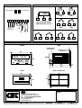
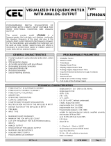
CONNECTIONS
INPUTSIGNALS
TTL LOGIC TTL LOGIC
NPN PNP
+ -
AMPLIFIED PROXIMIT
AND ENCODER - 24 Vdc
CONTACT CONTACT
NPN PNP
NPN PROGRAMMING PNP PROGRAMMING
RESET INHIBIT
NPN NPN
RESET INHIBIT
PNP PNP
OVERALL DIMENSIONS
FRONT SIDE
REAR DRILL TEMPLATE
CET
CETCET
CET
CET
CETCET
CET
s.r.l.
Strada Statale 211 Km 53,550
28071 Borgolavezzaro - NO - ITALY
Tel : ++39 0321-885180/885301/885807
Fax : ++39 0321-885560
info@cet-italy.com
www.cet-italy.com
Agent :
48
96
ENT
RES
PROG
L1
L2
63125
Electronic counter
LFM
CET
139
115
9
15
44x92
MORSETTIERA
ESTRAIBILE
SQUADRETTE DI
FISSAGGIO
10
MAX
93
45
PROX
ENCOD
5
7
6
7
6
7
5
6
7
5
7
6
8
6
9
5
8
5
9
RESET
9
8
13
INHIBIT
11
10
12
RL2
RL1
-
+
AC
24 VDC
POWER SUPPLY
+
-
24 VDC
1
2
3
4
5
6
7
INPUT
92
44
1 2 3 4 5 6 7 8 9 10 11 12 13
-
 1
1
-
 2
2
-
 3
3
-
 4
4
-
 5
5
-
 6
6
-
 7
7
-
 8
8


in altre lingue
- English: CET LFM52 Owner's manual
Documenti correlati
-
 CET LFM50 Manuale del proprietario
-
 CET LFM40AN Manuale del proprietario
-
 CET GFM41 Manuale del proprietario
-
 CET NCM50 Manuale del proprietario
-
 CET LCM60 Manuale del proprietario
-
 CET GFM50 Manuale del proprietario
-
 CET GFM40 Manuale del proprietario
-
 CET LCM81 Manuale del proprietario
-
 CET NCM52 Manuale del proprietario
-
 CET GCM50 Manuale del proprietario


Altri documenti
-
 Chemitec 4222 Technical Manual
-
Omega CN245 Series Manuale del proprietario
-
Omega CN243 Series Manuale del proprietario
-
Carel IR32C Manuale utente
-
-
red lion IMP Manuale utente
-
-
SEA Gate 1 DG R1 Manuale del proprietario
-
