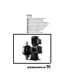
Grundfos DMM 23 Installation And Operating Instructions Manual
- Tipo
- Installation And Operating Instructions Manual

DMM
Variant B
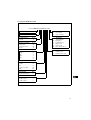
Installation and operating instructions
Montage- und Betriebsanleitung
Notice d’installation et d’entretien
Istruzioni di installazione e funzionamento
Instrucciones de instalación y funcionamiento
Instruções de instalação e funcionamento
ÂÅÁ½ÃÐÃÁÈ¿ÒºÑÒ¿ÑÅÐÈ¿ÇÉÃÇÒÍÓÏÁ½¿Ð
Installatie- en bedieningsinstructies
Monterings- och driftsinstruktion
Asennus- ja käyttöohjeet
Monterings- og driftsinstruktion
TM01 2553 2698
TM01 9683 3600
TM01 xxxx xxxx
TM02 0134 4000

Declaration of Conformity
We GRUNDFOS declare under our sole responsibility that the products
DMM, to which this declaration relates, are in conformity with the Coun-
cil Directives on the approximation of the laws of the EEC Member
States relating to
– Machinery (98/37/EEC).
Standard used: EN 292.
– Electromagnetic compatibility (89/336/EEC).
Standards used: EN 61 000-6-2 and EN 61 000-6-3.
– Electrical equipment designed for use within certain voltage limits
(73/23/EEC).
Standards used: EN 60 335-1 and EN 60 335-2-41.
Konformitätserklärung
Wir GRUNDFOS erklären in alleiniger Verantwortung, daß die Pro-
dukte DMM, auf die sich diese Erklärung bezieht, mit den folgenden
Richtlinien des Rates zur Angleichung der Rechtsvorschriften der EG-
Mitgliedstaaten übereinstimmen:
– Maschinen (98/37/EWG).
Norm, die verwendet wurde: EN 292.
– Elektromagnetische Verträglichkeit (89/336/EWG).
Normen, die verwendet wurden: EN 61 000-6-2 und EN 61 000-6-3.
– Elektrische Betriebsmittel zur Verwendung innerhalb bestimmter
Spannungsgrenzen (73/23/EWG).
Normen, die verwendet wurden: EN 60 335-1 und EN 60 335-2-41.
Déclaration de Conformité
Nous GRUNDFOS déclarons sous notre seule responsabilité que les
produits DMM auxquels se réfère cette déclaration sont conformes aux
Directives du Conseil concernant le rapprochement des législations
des Etats membres CEE relatives à
– Machines (98/37/CEE).
Standard utilisé: EN 292.
– Compatibilité électromagnétique (89/336/CEE).
Standards utilisés: EN 61 000-6-2 et EN 61 000-6-3.
– Matériel électrique destiné à employer dans certaines limites de
tension (73/23/CEE).
Standards utilisés: EN 60 335-1 et EN 60 335-2-41.
Dichiarazione di Conformità
Noi GRUNDFOS dichiariamo sotto la nostra esclusiva responsabilità
che i prodotti DMM ai quali questa dichiarazione se riferisce sono con-
formi alle Direttive del Consiglio concernente il ravvicinamento delle
legislazioni degli Stati membri CEE relative a
– Macchine (98/37/CEE).
Standard usato: EN 292.
– Compatibilità elettromagnetica (89/336/CEE).
Standard usati: EN 61 000-6-2 e EN 61 000-6-3.
– Materiale elettrico destinato ad essere utilizzato entro certi limiti di
tensione (73/23/CEE).
Standard usati: EN 60 335-1 e EN 60 335-2-41.
Declaración de Conformidad
Nosotros GRUNDFOS declaramos bajo nuestra única responsabilidad
que los productos DMM a los cuales se refiere esta declaración son
conformes con las Directivas del Consejo relativas a la aproximación
de las legislaciones de los Estados Miembros de la CEE sobre
– Máquinas (98/37/CEE).
Norma aplicada: EN 292.
– Compatibilidad electromagnética (89/336/CEE).
Normas aplicadas: EN 61 000-6-2 y EN 61 000-6-3.
– Material eléctrico destinado a utilizarse con determinadas límites
de tensión (73/23/CEE).
Normas aplicadas: EN 60 335-1 y EN 60 335-2-41.
'HFODUDomRGH&RQIRUPLGDGH
Nós GRUNDFOS declaramos sob nossa única responsabilidade que
os produtos DMM aos quais se refere esta declaração estão em con-
formidade com as Directivas do Conselho das Comunidades
Europeias relativas à aproximação das legislações dos Estados Mem-
bros respeitantes à
– Máquinas (98/37/CEE).
Norma utilizada: EN 292.
– Compatibilidade electromagnética (89/336/CEE).
Normas utilizadas: EN 61 000-6-2 e EN 61 000-6-3.
– Material eléctrico destinado a ser utilizado dentro de certos limites
de tensão (73/23/CEE).
Normas utilizadas: EN 60 335-1 e EN 60 335-2-41.
¢¼É×ÑűÓÊÊÚÏÔ×ÑÅÐ
¢É¼ÏÄ+692(*37ÁÄÈÛÊÌÒÉÂɾÍÌÇÈÂÆÐÑÆǹÁÆǻɾÏÂÒÅÚÊÄ
ÙÑÆѾÍÎÌÆÙÊѾ
DMMÐÒÉÉÌÎÓÛÊÌÊѾÆÉÂÑÄʬÁÄÀ¼¾ÑÌÒ
°ÒÉ¿ÌÒȼÌÒÂͼÑÄÏÐÚÀÇÈÆÐÄÏÑÖÊÊÙÉÖÊÑÖʧξÑÛÊ0ÂÈÛÊÑÄÏ
¢ÒÎÖ;ÆǻϢÊÖÐÄÏÐÂÐÔºÐÄÉÂѾ
v ©ÄԾʻɾѾ((&
ÎÙÑÒÍÌÍÌÒÔÎÄÐÆÉÌÍÌÆ»ÅÄÇÂ(1
v ¤ÈÂÇÑÎÌɾÀÊÄÑÆÇ»ÐÒÉ¿¾ÑÙÑÄѾ((&
ÎÙÑÒ;ÍÌÒÔÎÄÐÆÉÌÍÌÆ»ÅÄǾÊ(1ǾÆ
(1
v ¤ÈÂÇÑÎÆǺÏÐÒÐÇÂÒºÏÐÔÂÁƾÐɺÊÂÏÀƹÔλÐÄÂÊÑÙÏÌÎÆÐɺÊÖÊ
ÌμÖÊÄÈÂÇÑÎÆÇ»ÏѹÐÄÏ((&
ÎÙÑÒ;ÍÌÒÔÎÄÐÆÉÌÍÌÆ»ÅÄǾÊ(1ǾÆ
(1
Overeenkomstigheidsverklaring
Wij GRUNDFOS verklaren geheel onder eigen verantwoordelijkheid
dat de produkten DMM waarop deze verklaring betrekking heeft in
overeenstemming zijn met de Richtlijnen van de Raad inzake de
onderlinge aanpassing van de wetgevingen van de Lid-Staten
betreffende
– Machines (98/37/EEG).
Norm: EN 292.
– Elektromagnetische compatibiliteit (89/336/EEG).
Normen: EN 61 000-6-2 en EN 61 000-6-3.
– Elektrisch materiaal bestemd voor gebruik binnen bepaalde
spanningsgrenzen (73/23/EEG).
Normen: EN 60 335-1 en EN 60 335-2-41.
Försäkran om överensstämmelse
Vi GRUNDFOS försäkrar under ansvar, att produkterna DMM, som
omfattas av denna försäkran, är i överensstämmelse med Rådets
Direktiv om inbördes närmande till EU-medlemsstaternas lagstiftning,
avseende
– Maskinell utrustning (98/37/EC).
Använd standard: EN 292.
– Elektromagnetisk kompatibilitet (89/336/EC).
Använda standarder: EN 61 000-6-2 och EN 61 000-6-3.
– Elektrisk material avsedd för användning inom vissa spännings-
gränser (73/23/EC).
Använda standarder: EN 60 335-1 och EN 60 335-2-41.
Vastaavuusvakuutus
Me GRUNDFOS vakuutamme yksin vastuullisesti, että tuotteet DMM,
jota tämä vakuutus koskee, noudattavat direktiivejä jotka käsittelevät
EY:n jäsenvaltioiden koneellisia laitteita koskevien lakien yhdenmukai-
suutta seur.:
– Koneet (98/37/EY).
Käytetty standardi: EN 292.
– Elektromagneettinen vastaavuus (89/336/EY).
Käytetyt standardit: EN 61 000-6-2 ja EN 61 000-6-3.
– Määrättyjen jänniterajoitusten puitteissa käytettävät sähköiset
laitteet (73/23/EY).
Käytetyt standardit: EN 60 335-1 ja EN 60 335-2-41.
Overensstemmelseserklæring
Vi GRUNDFOS erklærer under ansvar, at produkterne DMM, som
denne erklæring omhandler, er i overensstemmelse med Rådets direk-
tiver om indbyrdes tilnærmelse til EF medlemsstaternes lovgivning om
– Maskiner (98/37/EØF).
Anvendt standard: EN 292.
– Elektromagnetisk kompatibilitet (89/336/EØF).
Anvendte standarder: EN 61 000-6-2 og EN 61 000-6-3.
– Elektrisk materiel bestemt til anvendelse inden for visse
spændingsgrænser (73/23/EØF).
Anvendte standarder: EN 60 335-1 og EN 60 335-2-41.
Bjerringbro, 1st April 2002
Jan Strandgaard
Technical Manager

DMM
Variant B
Installation and
operating instructions
Page 4
Montage- und
Betriebsanleitung
Seite 14
Notice d’installation
et d’entretien
Page 25
Istruzioni di installazione
e funzionamento
Pag. 35
Instrucciones de instalación
y funcionamiento
Pág. 45
Instruções de instalação
e funcionamento
Pág. 55
ÂÅÁ½ÃÐÃÁÈ¿ÒºÑÒ¿ÑÅÐ
È¿ÇÉÃÇÒÍÓÏÁ½¿Ð
°ÂȼÁ¾
Installatie- en
bedieningsinstructies
Pag. 75
Monterings- och
driftsinstruktion
Sida 85
Asennus- ja
käyttöohjeet
Sivu 95
Monterings- og
driftsinstruktion
Side 105

4
CONTENTS
Page
1. General description 4
1.1 Applications 4
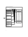
1.2 Type key, DMM 4 to 390 5
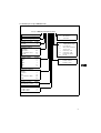
1.3 Type key, DMM 440 to 990 6
2. Technical data, DMM 4 to 390 7
2.1 Operating conditions 7
2.2 Electrical motor data 7
2.3 Dimensions 7
2.4 Performance curves 7
3. Technical data, DMM 440 to 990 8
3.1 Operating conditions 8
3.2 Electrical motor data 8
3.3 Dimensions 8
3.4 Performance curves 8
4. Installation 9
4.1 Safety instructions 9
4.2 Precautions 9
4.3 Installation of pump 9
4.4 Installation example 10
4.5 Installation components 11
4.6 Electrical connection 12
5. Stroke length setting 12
6. Start-up 12
7. Maintenance 12
7.1 Service kits 12
7.2 Replacement of diaphragm 12
8. Service 12
9. Fault finding chart 13
10. Disposal 13
Before beginning installation procedures,
these installation and operating instruc-
tions should be studied carefully. The in-
stallation and operation should also be in
accordance with local regulations and ac-
cepted codes of good practice.
1. General description
The GRUNDFOS DMM dosing pump is a self-prim-
ing diaphragm pump, consisting of a dosing head
with diaphragm, a gear, and a motor.
1.1 Applications
The DMM dosing pump is designed for handling
chemicals within the following ranges of applications:
• Drinking water treatment.
• Waste water treatment.
• Swimming baths and pool water treatment.
• Industrial water treatment.
• Water treatment in district heating plants.
• Water treatment at farms and market gardens.

5
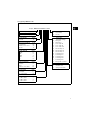
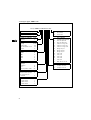
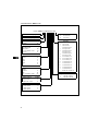
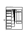
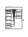
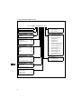
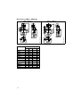
1.2 Type key, DMM 4 to 390
Example
:
Maximum capacity [l/h]
Control variant Code
Standard B
Dosing head material Code
Polypropylene PP
Stainless steel 1.4571 SS
Special Z
Code Mains plug
FEU (Schuko)
X No plug
Code
Connection,
suction/discharge
4 Tubing 6/9
5 Tubing 6/12
7 Hose clamp d.6
8 Hose clamp d.9
9 Hose clamp d.16
A Threaded Rp 1/4
B Threaded Rp 3/8
C Threaded Rp 1/2
E Cementing d.10
F Cementing d.12
G Cementing d.16
H Cementing d.20
I Cementing d.25
L Flange, DN 15, PN 16
Code Valves
1 Standard valve
2 Spring-loaded valve
Valve ball material Code
Ceramics C
Glass G
Stainless steel 1.4401 SS
Gasket material Code
EPDM E
FKM V
PTFE T
CSM H
AF A
Maximum pressure [bar]
Control panel Code
Front-fitted F
No control panel X
Voltage Code
1 x 230 V, 50 Hz 1
3 x 400 V, 50 Hz 4
3 x 440 V, 60 Hz 5
DMM 4-10 B-PP/E/G-F-4 1 4A F

6
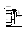
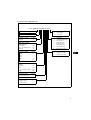
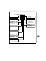
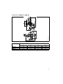
1.3 Type key, DMM 440 to 990
Example
:
Maximum capacity [l/h]
Control variant Code
Standard B
Dosing head material Code
Polypropylene PP
Stainless steel 1.4571 SS
Special Z
Code Mains plug
FEU (Schuko)
X No plug
Code
Connection,
suction/discharge
D Threaded Rp 1
P Hose clamp d.25
J Cementing d.32
K Cementing d.40
M Flange, DN 25, PN 16
Code Valves
1 Standard valve
2 Spring-loaded valve
Valve ball material Code
Ceramics C
Glass G
Stainless steel 1.4401 SS
PVDF PV
Gasket material Code
EPDM E
FKM V
PTFE T
CSM H
AF A
Maximum pressure [bar]
Control panel Code
No control panel X
Voltage Code
3 x 400 V, 50 Hz 4
3 x 440 V, 60 Hz 5
DMM 440-5 B-PP/E/G-X-4 1 DJ F

7
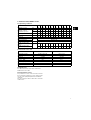
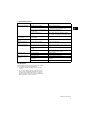
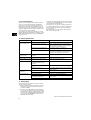
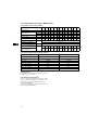
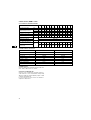
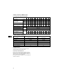
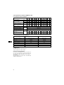
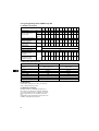
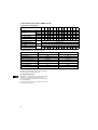
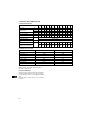
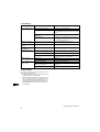
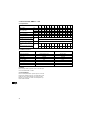
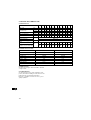
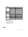
2. Technical data, DMM 4 to 390
2.1 Operating conditions
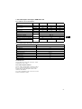
2.2 Electrical motor data
2.3 Dimensions
See dimensions at the end of these instructions.
All dimensions are in mm.
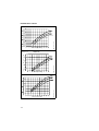
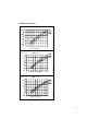
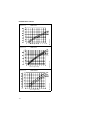
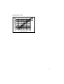
2.4 Performance curves
See performance curves at the end of these instruc-
tions. The pump performance curves depend on the
viscosity of the pumped liquid and the installation
conditions.
The curves apply to water at 18°C and a suction lift
of 0.6 metres.
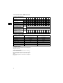
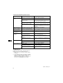
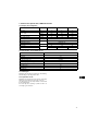
DMM 4 8 15 23 48 72 110 155 160 210 260 290 390
Maximum pressure bar 101010101010 5 4 101010 8 6
Maximum capacity
at maximum pressure
l/h 4 8 15 23 48 72 110 155 160 210 260 290 390
ml/
stroke
2.6 2.6 2.6 2.6 8.5 8.5 19 19 37 37 37 51 55
Diaphragm diameter mm 52 52 52 52 64 64 90 90 120 120 120 150 150
Maximum stroke frequency 1/min. 26 48 95 142 95 142 95 142 71 95 120 95 120
Suction lift m 5 53.82.543.32.52 32.522.52
Ambient temperature
°C
Maximum 40
Liquid temperature Maximum 50
Accuracy of repeatability % ±2
Weight (dosing head of
plastic)
kg
7.4 7.4 7.4 7.4 7.6 7.6 9.2 9.2 16 16 16 18 18
Weight (dosing head of
stainless steel)
11 11 11 11 12 12 20 20 22 22 22 26 26
DMM 4, 8, 15, 23, 48, 72, 110, 155 160, 210, 260, 290, 390
Standard motor type 63 RF 0.12/4-71R K21R 71 64
Speed [min.
-1
] 1400 1430
Voltage [V] 230/400 230/400
Rated current [A] 0.76/0.44 1.75/1.0
Power, P
2
[kW] 0.25 0.37
Frequency [Hz] 50 50
Enclosure class IP 55 IP 55
Insulation class B B

8
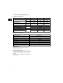
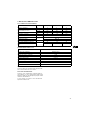
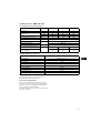
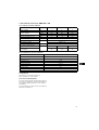
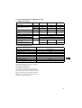
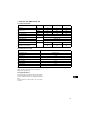
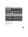
3. Technical data, DMM 440 to 990
3.1 Operating conditions
3.2 Electrical motor data
3.3 Dimensions
See dimensions at the end of these instructions.
All dimensions are in mm.
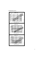
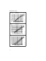
3.4 Performance curves
See performance curves at the end of these instruc-
tions. The pump performance curves depend on the
viscosity of the pumped liquid and the installation
conditions.
The curves apply to water at 18°C and a suction lift
of 0.6 metres.
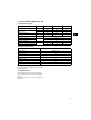
DMM 440 640 990
Maximum pressure bar 5 5 4
Maximum capacity
at maximum pressure
l/h 440 640 990
ml/stroke 165 165 165
Diaphragm diameter mm 185 185 185
Maximum stroke frequency 1/min. 47 70 101
Suction lift m 3
Ambient temperature
°C
Maximum 40
Liquid temperature Maximum 50
Accuracy of repeatability % ±2
Weight (dosing head of plastic)
kg
38 38 38
Weight (dosing head of stainless
steel)
48 48 48
DMM
Standard motor type 80 RF 0.55/4-7
Connection ∆/Y
Speed [min.
-1
] 1410
Voltage [V] 230/400
Rated current [A] 2.6/1.55
Power, P
2
[kW] 0.75
Frequency [Hz] 50
Enclosure class IP 55
Insulation class B

9
4. Installation
4.1 Safety instructions
• When working with chemicals, local safety rules
and regulations must be observed (e.g. wear pro-
tective clothes).
• Before starting work on the dosing pump and sys-
tem, disconnect the electricity supply to the pump,
ensuring that it cannot be accidentally switched
on. Before reconnecting the electricity supply,
make sure that the dosing line is positioned in
such a way that any chemical left in the dosing
head is not ejected, thereby exposing persons to
danger.
• The dosing head, connections, and dosing lines of
the system may be under pressure. Work on dos-
ing systems requires special safety precautions
and should only be carried out by instructed per-
sons.
• If dosing head connections are unscrewed during
operation for venting or other purposes, make
sure that any leaking chemical is removed imme-
diately. This is important in order to avoid the risk
of personal injury and corrosion of the pump and
system.
• When changing a chemical, make sure that the
materials of the dosing pump and system are re-
sistant to the new chemical.
• If there is any risk of chemical reaction between
the two types of chemicals, clean the pump and
system thoroughly before adding the new chemi-
cal.
• After changing the cable entries to the pump, en-
sure that the screwed cable entries are thoroughly
tightened.
4.2 Precautions
Note:
• When selecting a dosing pump in connection with
the construction of a system as well as the instal-
lation and operation of the pump, make sure that
local rules are observed. This applies to the selec-
tion of suitable pump materials, the handling of
the chemical as well as the electrical connection.
• Consider the technical data of the dosing pump in
connection with the selection, installation, and op-
eration of the pump. The system should be de-
signed according to the technical data (e.g. pres-
sure loss in lines depending on diameter and
length).
• Always use suitable tools for the mounting of plas-
tic parts. Never apply unnecessary force. Plastic
parts are fitted and removed more easily if the
thread is lubricated with vaseline or silicone
grease prior to the fitting/removal.
• Make sure that the dosing pump and system are
designed in such a way that neither system equip-
ment nor buildings are damaged in case of leak-
age from the pump or rupture of hoses/pipes. The
installation of leakage lines and collecting tanks is
recommended.
• The dosing pump is manufactured according to
the highest quality standards ensuring long life.
Nevertheless, the pump contains wearing parts,
such as diaphragm, valve seats, and valve balls.
To ensure long life and to minimize the risk of in-
terruption of operation, visual checks should be
carried out at regular intervals. Operating and
maintenance personnel should therefore have free
access to the dosing pump.
4.3 Installation of pump
• See also the installation example in section 4.4.
• Always install the pump on the supporting foot
with vertical suction and discharge ports.
• Ensure that the pipes connected are not twisted in
the pump connections.
• Make sure that the drain hole in the dosing head
points downwards.
• Note: It is important that the drain pipe is not in-
serted direct into the tank contents, as gasses
may penetrate into the pump.
Lead the drain pipe to a vented collecting tank.
Alternatively, lead the drain pipe to a collecting
funnel above the tank (see the installation exam-
ple in section 4.4). In the latter case, sufficient dis-
tance must be kept between pipe and funnel,
which also makes it possible to actually see a pos-
sible leakage.

10
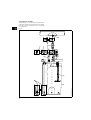
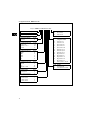
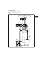
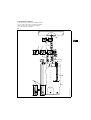
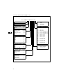
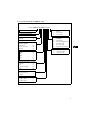
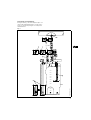
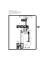
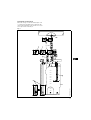
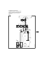
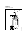
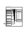
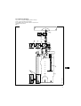
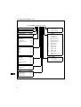
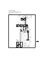
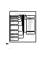
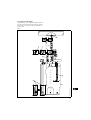
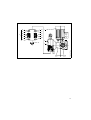
4.4 Installation example
The drawing in fig. 1 shows a typical system with the
components suitable for the application. The individ-
ual components are described in section 4.5 Installa-
tion components.
Fig. 1
TM01 9961 3500

11
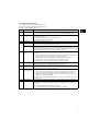
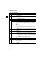
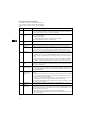
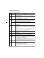
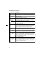
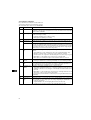
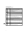
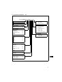
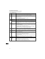
4.5 Installation components
The position numbers refer to the numbers in the
drawing in section 4.4 Installation example. All com-
ponents are GRUNDFOS accessories.
Pos. Designation Description
1 Tank Polyethylene chemical tank made ready for the installation of pump, suction line, and
hand mixer. The tank is available in several sizes between 60 and 1000 litres.
2 Suction line Suction line for installation in tank. Three different types are available:
1. Simple foot valve.
2. Flexible suction line with foot valve and hose.
3. Rigid suction line with foot valve.
3 Hand mixer Manual mixer (stamper) for tank.
4 Head vent Manual vent for direct mounting on the pump discharge connection. The outlet
hose of the vent should be connected to the tank.
GAS-EX Automatic degassing device for direct mounting on the pump discharge connection.
The degassing device can be set to open at intervals from every 30 seconds to every
45 minutes. The opening duration can be set between 0.5 and 10 seconds. The outlet
hose of the degassing device should be connected to the tank.
5 Multifunction
valve
Valve block for direct mounting on the pump discharge connection.
Functions:
1. Counter-pressure valve to optimize the dosing accuracy. At the same time, the
valve prevents excessive dosing in pressureless systems.
2. Antisiphon function to prevent undesired siphoning from the system.
3. Relief valve to protect the pump against excessive pressure.
4. By-pass valve for pressureless return of the liquid to the tank.
6 Flow indicator Flow indicator for direct mounting on the pump discharge connection. Used for dos-
ing monitoring by means of a jumping ball in a transparent pipe.
7 Pulsation damp-
ener PDS
Pulsation dampener for reducing pressure surges at dosing strokes, thereby en-
suring a steady dosing flow. The dampener is particularly suitable for long dis-
charge lines and/or lines with a small diameter.
8 Counter-pres-
sure/relief valve
Adjustable counter-pressure/relief valve with the following functions:
1. Counter-pressure/relief function if a constant counter-pressure is required to
obtain a steady flow, irrespective of pressure variations in the system.
2. Relief valve protecting the pump against excessive pressure. The outlet hose
should be connected to the tank.
The valve shown in the installation example in section 4.4 is installed as a counter-
pressure valve.
9 Injection valve Injection valve consisting of an injection pipe, a non-return valve, and a connection.
10 Priming aid Priming aid for direct mounting on the pump suction connection. Particularly suita-
ble for high suction lifts and/or long suction lines. Designed for the following pur-
poses:
1. To facilitate priming when starting the pump.
2. To collect undesired air in the suction line during operation.

12
4.6 Electrical connection
• The electrical connection of the pump should be
carried out by qualified persons in accordance
with local regulations.
• For electrical data of the pump, see sections 2.2
and 3.2.
• Connect the motor to a motor starter which should
be set according to the motor data.
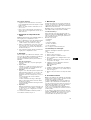
5. Stroke length setting
Note: The pump must be operating when the stroke
length is set.
Set the stroke length in the following way:
1. Loosen the locking screw in the middle (counter-
clockwise).
2. Set the stroke length to the desired value, ac-
cording to the performance table on the pump or
the performance curves at the end of these in-
structions.
3. Retighten the locking screw while the stroke
length setting is maintained.
6. Start-up
Before beginning the start-up procedure, make sure
that the pump has been installed correctly and the
electricity supply has been switched on.
Follow this procedure when starting the pump:
1. Gear oil.
Fill the pump with the gear oil supplied.
2. Starting the motor.
Check that the direction of rotation of the motor is
correct. The correct direction is indicated by an
arrow on the fan cover.
3. Priming.
Set the pump to maximum stroke frequency (for
further details, see section 5. Stroke length set-
ting) and allow the pump to operate without coun-
ter-pressure (if possible).
If self-priming is not successful:
1. Stop the pump.
2. Remove the discharge valve and pour clean
water or a harmless chemical into the dosing
head.
3. Reinstall the discharge valve and allow the
pump to self-prime.
4. Setting.
When the pump is primed and operates at the
correct counter-pressure, set the stroke length,
see section 5. Stroke length setting.
If the pump does not work as intended, it is advisable
to refer to section 9. Fault finding chart.
7. Maintenance
The dosing pump is maintenance-free. However, it is
recommended to renew the gear oil of the pump after
approx. 5000 operating hours.
Recommended oil quality: Viscosity class
ISO-VT 100 (corresponding to SAE 30).
7.1 Service kits
A service kit is available for all GRUNDFOS dosing
pumps. The kit consists of all wearing parts for the
individual pump type.
The service kit includes:
• Diaphragm,
• O-rings,
• Gaskets,
• Valve balls,
• Valve seats.
See the product numbers at the end of these instruc-
tions.
7.2 Replacement of diaphragm
Replace the pump diaphragm in the following way:
1. Stop the pump.
2. Remove the dosing head.
3. Remove the fan cover from the motor.
4. Turn the fan until the diaphragm is in the outer
position.
5. Unscrew the diaphragm (counter-clockwise).
6. Grease the diaphragm rod.
Recommended lubricants:
Molycote BR 2 Plus.
OKS 400.
7. Check that the seal washer behind the diaphragm
rests in the groove of the diaphragm rod.
8. Screw on the new diaphragm (clockwise).
9. Mount the dosing head and the fan cover.
8. Service
Note: If a pump has been used for a liquid which is
injurious to health or toxic, the pump will be classi-
fied as contaminated.
If GRUNDFOS is requested to service the pump, it
must be ensured that the pump is free from sub-
stances that can be injurious to health or toxic. If the
pump has been used for such substances, the pump
must be cleaned before it is returned.
If proper cleaning is not possible, all relevant infor-
mation about the chemical must be provided.
If the above is not fulfilled, GRUNDFOS can refuse
to accept the pump for service. Possible costs of re-
turning the pump are paid by the customer.

13
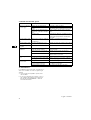
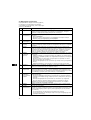
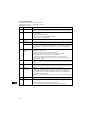
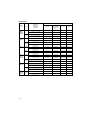
9. Fault finding chart
10. Disposal
Disposal of this product or parts of it must be carried
out according to the following guidelines:
1. Use the local public or private waste collection
service.
2. In case such waste collection service does not
exist or cannot handle the materials used in the
product, please deliver the product or any haz-
ardous materials from it to your nearest GRUND-
FOS company or service workshop.
Fault Cause Remedy
Motor is running, but
the pump is not dosing.
Valve blocked or leaking. Check and clean valves.
Valves incorrectly installed. Reinstall valves. Ensure that the valve balls
are positioned above the valve seats.
Suction valve or suction line leak-
ing or blocked.
Clean and seal suction line.
No stroke movement. Return spring defective. Replace spring.
Check that counter-pressure and suction pres-
sure of pump are within the permissible range.
Pump dosing too little
or too much.
Stroke length control knob incor-
rectly installed.
Install the knob correctly.
Pump dosing too
much.
Suction pressure too high. Install counter-pressure valve in discharge
line.
Pump dosing irregu-
larly.
Valve blocked or leaking. Check and clean valves.
Frequent diaphragm
failures.
Diaphragm not fastened properly to
the diaphragm rod.
Install new diaphragm to ensure that the dia-
phragm is fastened properly.
Pressure surges at dosing strokes
too high.
Install pulsation dampener.
Excessive counter-pressure. Check counter-pressure and adjustment of
counter-pressure valve, if any.
Pump too noisy. Defective bearing. Replace bearing.
No oil in gear box. Refill oil. Renew gear oil, if necessary.
Motor hums and does
not start.
Wrong connection. Check electrical connection.
Defective capacitor (single-phase
pumps only).
Check capacitor connection or replace it, if
necessary.
Excessive counter-pressure. Check discharge line for blocking.
Subject to alterations.

14
INHALTSVERZEICHNIS
Seite
1. Sicherheitshinweise 14
1.1 Allgemeines 14
1.2 Kennzeichnung von Hinweisen 14
1.3 Personalqualifikation und -schulung 14
1.4 Gefahren bei Nichtbeachtung der
Sicherheitshinweise 14
1.5 Sicherheitsbewußtes Arbeiten 14
1.6 Sicherheitshinweise für den Betreiber/
Bediener 15
1.7 Sicherheitshinweise für Wartungs-,
Inspektions- und Montagearbeiten 15
1.8 Eigenmächtiger Umbau und Ersatzteil-
herstellung 15
1.9 Unzulässige Betriebsweisen 15
2. Allgemeines 15
2.1 Verwendungszweck 15
2.2 Typenschlüssel, DMM 4 bis 390 16
2.3 Typenschlüssel, DMM 440 bis 990 17
3. Technische Daten, DMM 4 bis 390 18
3.1 Betriebsbedingungen 18
3.2 Elektrische Motordaten 18
3.3 Abmessungen 18
3.4 Förderkennlinien 18
4. Technische Daten, DMM 440 bis 990 19
4.1 Betriebsbedingungen 19
4.2 Elektrische Motordaten 19
4.3 Abmessungen 19
4.4 Förderkennlinien 19
5. Montage 20
5.1 Dosierung von Chemikalien 20
5.2 Vorsichtsmaßnahmen 20
5.3 Montage der Pumpe 20
5.4 Installationsbeispiel 21
5.5 Anlagenkomponenten 22
5.6 Elektrischer Anschluß 23
6. Hublängeneinstellung 23
7. Inbetriebnahme 23
8. Wartung 23
8.1 Servicesätze 23
8.2 Membranwechsel 23
9. Service 23
9.1 Verunreinigte Pumpen 23
9.2 Ersatzteile/Zubehör 24
10. Störungsübersicht 24
11. Entsorgung 24
1. Sicherheitshinweise
1.1 Allgemeines
Diese Montage- und Betriebsanleitung enthält grund-
legende Hinweise, die bei Aufstellung, Betrieb und
Wartung zu beachten sind. Sie ist daher unbedingt
vor Montage und Inbetriebnahme vom Monteur so-
wie dem zuständigen Fachpersonal/Betreiber zu le-
sen. Sie muß ständig am Einsatzort der Anlage ver-
fügbar sein.
Es sind nicht nur die unter diesem Abschnitt “Sicher-
heitshinweise” aufgeführten, allgemeinen Sicher-
heitshinweise zu beachten, sondern auch die unter
den anderen Abschnitten eingefügten, speziellen Si-
cherheitshinweise.
1.2 Kennzeichnung von Hinweisen
Direkt an der Anlage angebrachte Hinweise wie z.B.
• Drehrichtungspfeil
• Kennzeichnung für Fluidanschlüsse
müssen unbedingt beachtet und in vollständig lesba-
rem Zustand gehalten werden.
1.3 Personalqualifikation und -schulung
Das Personal für Bedienung, Wartung, Inspektion
und Montage muß die entsprechende Qualifikation
für diese Arbeiten aufweisen. Verantwortungsbe-
reich, Zuständigkeit und die Überwachung des Per-
sonals müssen durch den Betreiber genau geregelt
sein.
1.4 Gefahren bei Nichtbeachtung der
Sicherheitshinweise
Die Nichtbeachtung der Sicherheitshinweise kann
sowohl eine Gefährdung für Personen als auch für
die Umwelt und Anlage zur Folge haben. Die Nicht-
beachtung der Sicherheitshinweise kann zum Ver-
lust jeglicher Schadenersatzansprüche führen.
Im einzelnen kann Nichtbeachtung beispielsweise
folgende Gefährdungen nach sich ziehen:
• Versagen wichtiger Funktionen der Anlage
• Versagen vorgeschriebener Methoden zur War-
tung und Instandhaltung
• Gefährdung von Personen durch elektrische und
mechanische Einwirkungen
1.5 Sicherheitsbewußtes Arbeiten
Die in dieser Montage- und Betriebsanleitung aufge-
führten Sicherheitshinweise, die bestehenden natio-
nalen Vorschriften zur Unfallverhütung sowie even-
tuelle interne Arbeits-, Betriebs- und Sicherheitsvor-
schriften des Betreibers, sind zu beachten.
Die in dieser Montage- und Betriebsan-
leitung enthaltenen Sicherheitshin-
weise, die bei Nichtbeachtung Gefähr-
dungen für Personen hervorrufen kön-
nen, sind mit allgemeinem Gefahren-
symbol “Sicherheitszeichen nach DIN
4844-W9” besonders gekennzeichnet.
Dieses Symbol finden Sie bei Sicher-
heitshinweisen, deren Nichtbeachtung
Gefahren für die Maschine und deren
Funktionen hervorrufen kann.
Hier stehen Ratschläge oder Hinweise,
die das Arbeiten erleichtern und für ei-
nen sicheren Betrieb sorgen.
Achtung
Hinweis

15
1.6 Sicherheitshinweise für den Betreiber/
Bediener
• Ein vorhandener Berührungsschutz für sich bewe-
gende Teile darf bei einer sich in Betrieb befindli-
chen Anlage nicht entfernt werden.
• Gefährdungen durch elektrische Energie sind aus-
zuschließen (Einzelheiten hierzu siehe z.B. in den
Vorschriften des VDE und der örtlichen Energie-
versorgungsunternehmen).
1.7 Sicherheitshinweise für Wartungs-,
Inspektions- und Montagearbeiten
Der Betreiber hat dafür zu sorgen, daß alle War-
tungs-, Inspektions- und Montagearbeiten von auto-
risiertem und qualifiziertem Fachpersonal ausgeführt
werden, das sich durch eingehendes Studium der
Montage- und Betriebsanleitung ausreichend infor-
miert hat.
Grundsätzlich sind Arbeiten an der Pumpe nur im
Stillstand durchzuführen. Die in der Montage- und
Betriebsanleitung beschriebene Vorgehensweise
zum Stillsetzen der Anlage muß unbedingt eingehal-
ten werden.
Unmittelbar nach Abschluß der Arbeiten müssen alle
Sicherheits- und Schutzeinrichtungen wieder ange-
bracht bzw. in Funktion gesetzt werden.
Vor der Wiederinbetriebnahme sind die im Abschnitt
7. Inbetriebnahme aufgeführten Punkte zu beachten.
1.8 Eigenmächtiger Umbau und Ersatzteil-
herstellung
Umbau oder Veränderungen an Pumpen sind nur
nach Absprache mit dem Hersteller zulässig. Origi-
nalersatzteile und vom Hersteller autorisiertes Zube-
hör dienen der Sicherheit. Die Verwendung anderer
Teile kann die Haftung für die daraus entstehenden
Folgen aufheben.
1.9 Unzulässige Betriebsweisen
Die Betriebssicherheit der gelieferten Pumpen ist nur
bei bestimmungsgemäßer Verwendung entspre-
chend Abschnitt 2.1 Verwendungszweck der Mon-
tage- und Betriebsanleitung gewährleistet. Die in
den technischen Daten angegebenen Grenzwerte
dürfen auf keinen Fall überschritten werden.
2. Allgemeines
GRUNDFOS DMM Dosierpumpen sind selbstansau-
gende Membranpumpen, bestehend aus Dosierkopf
mit Membrane, Getriebe und Motor.
2.1 Verwendungszweck
DMM Dosierpumpen sind für den Einsatz von Che-
mikalien in folgenden Einsatzgebieten vorgesehen:
• Trinkwasseraufbereitung.
• Abwasseraufbereitung.
• Schwimmbad-Wasseraufbereitung.
• Industriewasseraufbereitung.
• Wasseraufbereitung in Fernheizungsanlagen.
• Wasseraufbereitung auf Bauernhöfen und in Han-
delsgärtnereien.

16
2.2 Typenschlüssel, DMM 4 bis 390
Beispiel:
Max. Förderstrom [l/h]
Steuerungsvariante Code
Standard B
Dosierkopfwerkstoff Code
Polypropylen PP
Edelstahl 1.4571 SS
Speziell Z
Code Netzstecker
FEU (Schuko)
X Kein Stecker
Code
Anschluß
Saug-/Druckseite
4 Schlauch 6/9
5 Schlauch 6/12
7 Spannband d.6
8 Spannband d.9
9 Spannband d.16
A Gewinde Rp 1/4
B Gewinde Rp 3/8
C Gewinde Rp 1/2
E Eingeklebt d.10
F Eingeklebt d.12
G Eingeklebt d.16
H Eingeklebt d.20
I Eingeklebt d.25
L Flansch, DN 15, PN 16
Code Ventile
1 Standardventil
2 Federbelastetes Ventil
Ventilkugelwerkstoff Code
Keramik C
Glas G
Edelstahl 1.4401 SS
Dichtungswerkstoff Code
EPDM E
FKM V
PTFE T
CSM H
AF A
Max. Druck [bar]
Bedientastatur Code
Frontmontiert F
Keine Bedientastatur X
Spannung Code
1 x 230 V, 50 Hz 1
3 x 400 V, 50 Hz 4
3 x 440 V, 60 Hz 5
DMM 4-10 B-PP/E/G-F-4 1 4A F

17
2.3 Typenschlüssel, DMM 440 bis 990
Beispiel
:
Max. Förderstrom [l/h]
Steuerungsvariante Code
Standard B
Dosierkopfwerkstoff Code
Polypropylen PP
Edelstahl 1.4571 SS
Speziell Z
Code Netzstecker
FEU (Schuko)
X Kein Stecker
Code
Anschluß
Saug-/Druckseite
DGewinde Rp 1
P Spannband d.25
J Eingeklebt d.32
K Eingeklebt d.40
M Flansch, DN 25, PN 16
Code Ventile
1 Standardventil
2 Federbelastetes Ventil
Ventilkugelwerkstoff Code
Keramik C
Glas G
Edelstahl 1.4401 SS
PVDF PV
Dichtungswerkstoff Code
EPDM E
FKM V
PTFE T
CSM H
AF A
Max. Druck [bar]
Bedientastatur Code
Keine Bedientastatur X
Spannung Code
3 x 400 V, 50 Hz 4
3 x 440 V, 60 Hz 5
DMM 440-5 B-PP/E/G-X-4 1 DJ F

18
3. Technische Daten, DMM 4 bis 390
3.1 Betriebsbedingungen
3.2 Elektrische Motordaten
3.3 Abmessungen
Siehe Abmessungen am Ende dieser Anleitung. Alle
Angaben sind in mm.
3.4 Förderkennlinien
Siehe Förderkennlinien am Ende dieser Anleitung.
Die Förderkennlinien hängen von der Viskosität des
dosierten Mediums und den Installationsbedingun-
gen ab.
Die Kennlinien gelten bei 18°C und einer Saughöhe
von 0,6 m.
DMM 4 8 15 23 48 72 110 155 160 210 260 290 390
Max. Druck bar 10 10 10 10 10 10 5 4 10 10 10 8 6
Max. Förderstrom
bei max. Druck
l/h 4 8 15 23 48 72 110 155 160 210 260 290 390
ml/Hub 2,6 2,6 2,6 2,6 8,5 8,5 19 19 37 37 37 51 55
Membrandurchmesser mm 5252525264649090120120120150150
Max. Hubfrequenz 1/min. 26 48 95 142 95 142 95 142 71 95 120 95 120
Saughöhe m 5 5 3,8 2,5 4 3,3 2,5 2 3 2,5 2 2,5 2
Umgebungstemperatur
°C
Max. 40
Temperatur des Dosier-
mediums
Max. 50
Wiederholgenauigkeit % ±2
Gewicht (Dosierkopf aus
Kunststoff)
kg
7,4 7,4 7,4 7,4 7,6 7,6 9,2 9,2 16 16 16 18 18
Gewicht (Dosierkopf aus
Edelstahl)
11 11 11 11 12 12 20 20 22 22 22 26 26
DMM 4, 8, 15, 23, 48, 72, 110, 155 160, 210, 260, 290, 390
Standardmotor, Typ 63 RF 0,12/4-71R K21R 71 64
Drehzahl [min.
-1
] 1400 1430
Spannung [V] 230/400 230/400
Nennstrom [A] 0,76/0,44 1,75/1,0
Leistung, P
2
[kW] 0,25 0,37
Frequenz [Hz] 50 50
Schutzart IP 55 IP 55
Wärmeklasse B B

19
4. Technische Daten, DMM 440 bis 990
4.1 Betriebsbedingungen
4.2 Elektrische Motordaten
4.3 Abmessungen
Siehe Abmessungen am Ende dieser Anleitung. Alle
Angaben sind in mm.
4.4 Förderkennlinien
SieheFörderkennlinien am Ende dieser Anleitung.
Die Förderkennlinien hängen von der Viskosität des
dosierten Mediums und den Installationsbedingun-
gen ab.
Die Kennlinien gelten bei 18°C und einer Saughöhe
von 0,6 m.
DMM 440 640 990
Max. Druck bar 5 5 4
Max. Förderstrom
bei max. Druck
l/h 440 640 990
ml/Hub 165 165 165
Membrandurchmesser mm 185 185 185
Max. Hubfrequenz 1/min. 47 70 101
Saughöhe m 3
Umgebungstemperatur
°C
Max. 40
Temperatur des Dosiermediums Max. 50
Wiederholgenauigkeit % ±2
Gewicht (Dosierkopf aus Kunststoff)
kg
38 38 38
Gewicht (Dosierkopf aus Edelstahl) 48 48 48
DMM
Standardmotor, Typ 80 RF 0,55/4-7
Anschluß ∆/Y
Drehzahl [min.
-1
] 1410
Spannung [V] 230/400
Nennstrom [A] 2,6/1,55
Leistung, P
2
[kW] 0,75
Frequenz [Hz] 50
Schutzart IP 55
Wärmeklasse B

20
5. Montage
5.1 Dosierung von Chemikalien
• Beim Arbeiten mit Chemikalien sind die am Ein-
satzort geltenden Unfallverhütungsvorschriften
anzuwenden (z.B. Tragen von Schutzkleidung).
• Bevor an der Dosierpumpe und -anlage gearbeitet
wird, müssen Netzleitungen freigeschaltet und ge-
gen Wiedereinschalten gesichert werden. Vor
Wiedereinschalten der Versorgungsspannung
müssen die Dosierleitungen angeschlossen wer-
den, so daß im Dosierkopf vorhandene Chemika-
lie nicht herausspritzen kann und Menschen
gefährdet werden.
• Der Dosierkopf der Pumpe sowie Anlagenan-
schlüsse und Leitungen können unter Druck ste-
hen. Arbeiten an der Dosieranlage erfordern
besondere Sicherheitsvorkehrungen und dürfen
nur von eingewiesenem Fachpersonal durchge-
führt werden.
• Wenn Anschlüsse am Dosierkopf zwecks Entlüf-
tung oder aus anderen Gründen während des Be-
triebes gelöst wurden, muß übergelaufene Chemi-
kalie umgehend beseitigt werden. Nur so kann
eine gesundheitliche Gefährdung durch die Che-
mikalie verhindert und ein chemischer Angriff auf
Pumpe und Anlage vermieden werden.
• Bei Wechsel der Chemikalie ist eine Überprüfung
der eingesetzten Werkstoffe auf chemische Be-
ständigkeit an der Dosierpumpe und den übrigen
Anlagen erforderlich.
• Wenn die Gefahr einer chemischen Reaktion zwi-
schen den verschiedenen Medien besteht, müs-
sen Pumpe und Anlage vor dem Einsatz der
neuen Chemikalie gründlich gereinigt werden.
• Nach Änderung der elektrischen Anschlüsse müs-
sen die Kabelverschraubungen fest angezogen
werden.
5.2 Vorsichtsmaßnahmen
Achtung:
• Die Auswahl der Dosierpumpe bei der Planung ei-
ner Anlage sowie Montage und Betrieb müssen
unter Berücksichtigung der örtlich geltenden Vor-
schriften erfolgen. Dies gilt für die Auswahl von
geeigneten Werkstoffen der Pumpe, die Handha-
bung der Chemikalien und die elektrische Installa-
tion.
• Die technischen Daten der Dosierpumpe sind im
Zusammenhang mit Auswahl, Montage und Be-
trieb der Pumpe zu berücksichtigen. Die Anlage
sollte den technischen Daten entsprechend aus-
gelegt werden (z.B. Druckverlust in den Leitungen
abhängig von Durchmesser und Länge).
• Für die Montage von Kunststoffteilen sind stets
geeignete Werkzeuge zu verwenden. Es darf nur
angemessene Kraft aufgewendet werden. Kunst-
stoffteile lassen sich leichter verschrauben und lö-
sen, wenn das Gewinde zuvor mit Vaseline oder
Silikonfett geschmiert wurde.
• Es ist sicherzustellen, daß Dosierpumpe und -an-
lage so konzipiert sind, daß ein Chemikalienaus-
tritt aus der Pumpe oder beschädigten Schläu-
chen/Leitungen zu keinem Schaden an Anlagen-
teilen und Gebäuden führt. Der Einbau von Lek-
kageüberwachungen und Auffangwannen wird
empfohlen.
• Die Dosierpumpe ist nach höchsten Qualitätsstan-
dards für lange Gebrauchsdauer hergestellt wor-
den. Dennoch enthält sie Verschleißteile wie z.B.
Membrane, Ventilsitze und Ventilkugeln.
Um eine lange Lebensdauer zu gewährleisten und
das Risiko einer Betriebsunterbrechung zu mini-
mieren, sollten in regelmäßigen Abständen visu-
elle Kontrollen stattfinden. Aus diesem Grund muß
das Bedien- und Wartungspersonal freien Zugriff
auf die Dosierpumpe haben.
5.3 Montage der Pumpe
• Siehe auch Installationsbeispiel in Abschnitt 5.4.
• Die Pumpe ist immer mit Pumpenfuß und senk-
recht stehenden Saug- und Druckventilen anzu-
schließen.
• Es ist sicherzustellen, daß die Anlagenverrohrung
keinen Druck auf die Pumpenanschlüsse aus-
üben.
• Die Drainageableitung im Dosierkopf muß nach
unten zeigen.
• Die Drainageleitung in einen gasfreien Auffangbe-
hälter führen.
Alternativ kann sie mit Gefälle bis zu einem Auf-
fangtrichter oberhalb des Behälters geleitet wer-
den (siehe Installationsbeispiel in Abschnitt 5.4).
In diesem Fall muß genug Abstand zwischen
Leitungsende und Trichter herrschen, so daß
mögliche Leckage auch gesehen werden kann.
Es ist wichtig, daß die Drainageleitung
nicht direkt zurück in den Behälter zum
Dosiermedium geführt wird, da sonst
Ausgasungen in die Pumpe gelangen
könnten.
Achtung
La pagina sta caricando ...
La pagina sta caricando ...
La pagina sta caricando ...
La pagina sta caricando ...
La pagina sta caricando ...
La pagina sta caricando ...
La pagina sta caricando ...
La pagina sta caricando ...
La pagina sta caricando ...
La pagina sta caricando ...
La pagina sta caricando ...
La pagina sta caricando ...
La pagina sta caricando ...
La pagina sta caricando ...
La pagina sta caricando ...
La pagina sta caricando ...
La pagina sta caricando ...
La pagina sta caricando ...
La pagina sta caricando ...
La pagina sta caricando ...
La pagina sta caricando ...
La pagina sta caricando ...
La pagina sta caricando ...
La pagina sta caricando ...
La pagina sta caricando ...
La pagina sta caricando ...
La pagina sta caricando ...
La pagina sta caricando ...
La pagina sta caricando ...
La pagina sta caricando ...
La pagina sta caricando ...
La pagina sta caricando ...
La pagina sta caricando ...
La pagina sta caricando ...
La pagina sta caricando ...
La pagina sta caricando ...
La pagina sta caricando ...
La pagina sta caricando ...
La pagina sta caricando ...
La pagina sta caricando ...
La pagina sta caricando ...
La pagina sta caricando ...
La pagina sta caricando ...
La pagina sta caricando ...
La pagina sta caricando ...
La pagina sta caricando ...
La pagina sta caricando ...
La pagina sta caricando ...
La pagina sta caricando ...
La pagina sta caricando ...
La pagina sta caricando ...
La pagina sta caricando ...
La pagina sta caricando ...
La pagina sta caricando ...
La pagina sta caricando ...
La pagina sta caricando ...
La pagina sta caricando ...
La pagina sta caricando ...
La pagina sta caricando ...
La pagina sta caricando ...
La pagina sta caricando ...
La pagina sta caricando ...
La pagina sta caricando ...
La pagina sta caricando ...
La pagina sta caricando ...
La pagina sta caricando ...
La pagina sta caricando ...
La pagina sta caricando ...
La pagina sta caricando ...
La pagina sta caricando ...
La pagina sta caricando ...
La pagina sta caricando ...
La pagina sta caricando ...
La pagina sta caricando ...
La pagina sta caricando ...
La pagina sta caricando ...
La pagina sta caricando ...
La pagina sta caricando ...
La pagina sta caricando ...
La pagina sta caricando ...
La pagina sta caricando ...
La pagina sta caricando ...
La pagina sta caricando ...
La pagina sta caricando ...
La pagina sta caricando ...
La pagina sta caricando ...
La pagina sta caricando ...
La pagina sta caricando ...
La pagina sta caricando ...
La pagina sta caricando ...
La pagina sta caricando ...
La pagina sta caricando ...
La pagina sta caricando ...
La pagina sta caricando ...
La pagina sta caricando ...
La pagina sta caricando ...
La pagina sta caricando ...
La pagina sta caricando ...
La pagina sta caricando ...
La pagina sta caricando ...
La pagina sta caricando ...
La pagina sta caricando ...
La pagina sta caricando ...
La pagina sta caricando ...
La pagina sta caricando ...
La pagina sta caricando ...
-
 1
1
-
 2
2
-
 3
3
-
 4
4
-
 5
5
-
 6
6
-
 7
7
-
 8
8
-
 9
9
-
 10
10
-
 11
11
-
 12
12
-
 13
13
-
 14
14
-
 15
15
-
 16
16
-
 17
17
-
 18
18
-
 19
19
-
 20
20
-
 21
21
-
 22
22
-
 23
23
-
 24
24
-
 25
25
-
 26
26
-
 27
27
-
 28
28
-
 29
29
-
 30
30
-
 31
31
-
 32
32
-
 33
33
-
 34
34
-
 35
35
-
 36
36
-
 37
37
-
 38
38
-
 39
39
-
 40
40
-
 41
41
-
 42
42
-
 43
43
-
 44
44
-
 45
45
-
 46
46
-
 47
47
-
 48
48
-
 49
49
-
 50
50
-
 51
51
-
 52
52
-
 53
53
-
 54
54
-
 55
55
-
 56
56
-
 57
57
-
 58
58
-
 59
59
-
 60
60
-
 61
61
-
 62
62
-
 63
63
-
 64
64
-
 65
65
-
 66
66
-
 67
67
-
 68
68
-
 69
69
-
 70
70
-
 71
71
-
 72
72
-
 73
73
-
 74
74
-
 75
75
-
 76
76
-
 77
77
-
 78
78
-
 79
79
-
 80
80
-
 81
81
-
 82
82
-
 83
83
-
 84
84
-
 85
85
-
 86
86
-
 87
87
-
 88
88
-
 89
89
-
 90
90
-
 91
91
-
 92
92
-
 93
93
-
 94
94
-
 95
95
-
 96
96
-
 97
97
-
 98
98
-
 99
99
-
 100
100
-
 101
101
-
 102
102
-
 103
103
-
 104
104
-
 105
105
-
 106
106
-
 107
107
-
 108
108
-
 109
109
-
 110
110
-
 111
111
-
 112
112
-
 113
113
-
 114
114
-
 115
115
-
 116
116
-
 117
117
-
 118
118
-
 119
119
-
 120
120
-
 121
121
-
 122
122
-
 123
123
-
 124
124
-
 125
125
-
 126
126


Grundfos DMM 23 Installation And Operating Instructions Manual
- Tipo
- Installation And Operating Instructions Manual
in altre lingue
- English: Grundfos DMM 23
- français: Grundfos DMM 23
- español: Grundfos DMM 23
- Deutsch: Grundfos DMM 23
- Nederlands: Grundfos DMM 23
- português: Grundfos DMM 23
- dansk: Grundfos DMM 23
- svenska: Grundfos DMM 23
- suomi: Grundfos DMM 23
Documenti correlati
-
Grundfos DME 375 Installation And Operating Instructions Manual
-
Grundfos DME 2 series Installation And Operating Instructions Manual
-
Grundfos DMS 2 Installation And Operating Instructions Manual
-
-
-
-
-
Grundfos 96 00 53 77 Installation And Operating Instructions Manual
-
Altri documenti
-
Vetus Waste water / bilge pump type EMP140 Guida d'installazione
-
ProMinent S3Cb Operating Instructions Manual
-
-
-
Aqua HC 200 Istruzioni per l'uso
-
-
Philips DVP320/00 Manuale utente
-
CTX BOMBAPRO PH-RX Operating
-
Alemlube 334900 303000 Manuale utente
-
 SPX FLOW Viking Power Waste Water Pump Manuale utente
