
TLK48 B - TLK72 B
REGOLATORI ELETTRONICI DIGITALI
Quick Guide
Cod.: ENG/ITA - Vr. 02 - 17/04 - ISTR-FTLK4872BIE02
ASCON TECNOLOGIC S.r.l.
Viale Indipendenza 56, 27029 Vigevano (PV) ITALY
Tel.: +39 0381 69871 - FAX: +39 0381 698730
http:\\www.ascontecnologic.com
e-mail: [email protected]
Premessa
Nel presente manuale sono contenute le informazioni necessarie ad una
corretta installazione e le istruzioni per l’utilizzo e la manutenzione del pro-
dotto, si raccomanda pertanto di leggerlo attentamente e di conservarlo.
La presente pubblicazione è di esclusiva proprietà di Ascon Tecnologic S.r.l. la
quale pone il divieto assoluto di riproduzione e divulgazione, anche parziale, se
non espressamente autorizzata.
Ascon Tecnologic si riserva di apportare modifiche estetiche e funzionali in
qualsiasi momento e senza alcun preavviso.
Ascon Tecnologic ed i suoi legali rappresentanti non si ritengono in alcun modo re-
sponsabili per eventuali danni a persone, cose o animali derivanti da manomissioni,
uso improprio, errato o comunque non conforme alle caratteristiche dello strumento.
Qualora un guasto o un malfunzionamento dell’apparecchio possa
creare situazioni pericolose o dannose per persone, cose o animali
si ricorda che l’impianto deve essere predisposto con dispositivi
aggiuntivi atti a garantire la sicurezza.
Per maggiori informazioni scaricare, gratuitamente, il manuale d’uso completo
dal sito: www.ascontecnologic.com
1. Avvertenze per installazione ed uso
Uso consentito -
Lo strumento è stato concepito come apparecchio di misura e
regolazione in conformità con la normativa EN61010-1 per il funzionamento ad altitu-
dini sino a 2000 m. L’utilizzo dello strumento in applicazioni non espressamente pre-
viste dalla norma sopra citata deve prevedere tutte le adeguate misure di protezione.
Lo strumento NON può essere utilizzato in ambienti con atmosfera pericolosa
(infiammabile od esplosiva) senza una adeguata protezione. Si ricorda che l’in-
stallatore deve assicurarsi che le norme relative alla compatibilità elettromagne-
tica siano rispettate anche dopo l’installazione dello strumento, eventualmente
utilizzando appositi filtri.
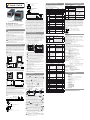
Montaggio meccanico
TLK48 B - Lo strumento, in contenitore 48 x 48 mm, è concepito per il montaggio
ad incasso a pannello entro un involucro. Praticare quindi un foro 45 x 45 mm ed
inserirvi lo strumento fissandolo con le apposite staffe fornite. Si raccomanda di
montare l’apposita guarnizione per ottenere il grado di protezione frontale dichiarato.
98
44.5
9.5
TLK4_
48
48
Panel + Gasket
max. 9 mm
Bracket type 1 Bracket type 2
45
45
TLK72 B - Lo strumento, in contenitore 72 x 72 mm, è concepito per il montaggio
ad incasso a pannello entro un involucro. Praticare quindi un foro da 66.5 x 66.5 mm
ed inserirvi lo strumento fissandolo con le apposite staffe fornite. Si raccomanda di
montare l’apposita guarnizione per ottenere il grado di protezione frontale dichiarato.
71
88
65.5
8
72
72
55
Panel + Gasket max. 5 mm
65.5
65.5
Brackets
Avvertenze generali per l’installazione -
Evitare di collocare la parte interna
dello strumento in luoghi soggetti ad alta umidità o sporcizia che possono provocare
condensa o introduzione nello strumento di parti o sostanze conduttive. Assicurarsi
che lo strumento abbia una adeguata ventilazione ed evitare l’installazione in conteni-
tori dove sono collocati dispositivi che possano portare lo strumento a funzionare al
di fuori dai limiti di temperatura dichiarati.
Installare lo strumento il più lontano possibile da fonti che possono generare
disturbi elettromagnetici come motori, teleruttori, relè, elettrovalvole ecc..
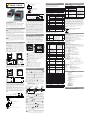
Collegamenti elettrici - Effettuare le connessioni collegando un solo conduttore
per morsetto e seguendo gli schemi sotto riportati, controllando che la tensione di
alimentazione sia quella indicata sullo strumento e che l’assorbimento degli attuatori
collegati allo strumento non sia superiore alla corrente massima consentita.
TLK48 B
NO
(max. 20 mA)
NTC/PTC
I
+
ext.
gen.
+
+
-
OUT 12 VDC
SUPPLY
4... 20 mA PASSIVE (2 wires)
4... 20 mA ACTIVE
4
Pt100
TC
INPUT
2
+
1 3
-
75 6 8
C
910
OUT2
NO
11
C
12
OUT1
+
-
+
-
+
+
-
+
-
+
-
SSR: 8 mA/8 VDC
Relays: 8A-AC1 (3A-AC3) 250VAC
4... 20 mA ACTIVE
0... 50/60 mV, 0... 1 V, 0/1... 5 V, 0/2... 10 V
TLK72 B
0... 50/60 mV; 0...1 V; 0/1...5 V; 0/2...10 V
0/4... 20 mA ACTIVE
C
OUT1
2122 20
+
Pt100
TC
-
+
1 23
PTC-NTC
-
+
+
+
-
gen.
ext.
+
I
+
+
-
-
NOC
13
SUPPLY
18
OUT2
19 17 16 15 14 12
4... 20 mA ACTIVE
54 678
OUT 12 VDC (max. 20 mA)
NC NO
+
-
+
4... 20 mA PASSIVE (2 wires)
SSR: 8 mA/8 VDC
Relays: 8A-AC1 (3A-AC3) 250VAC
Lo strumento, essendo previsto per collegamento permanente entro un’apparec-
chiatura, non è dotato né di interruttore né di dispositivi interni di protezione da
sovracorrenti. Si raccomanda pertanto di prevedere l’installazione di un interrut-
tore/sezionatore di tipo bipolare, marcato come dispositivo di disconnessione, che
interrompa l’alimentazione dell’apparecchio. Tale interruttore deve essere posto il
più possibile vicino allo strumento e in luogo facilmente accessibile dall’utilizzato-
re. Inoltre si raccomanda di proteggere adeguatamente tutti i circuiti connessi allo
strumento con dispositivi (es. fusibili) adeguati alle correnti circolanti.
Si raccomanda di utilizzare cavi con isolamento appropriato alle tensioni, alle tem-
perature e alle condizioni di esercizio e di fare in modo che i cavi relativi ai sensori
di ingresso siano tenuti lontani dai cavi di alimentazione e da altri cavi di potenza al
fine di evitare l’induzione di disturbi elettromagnetici. Se alcuni cavi utilizzati per il
cablaggio sono schermati si raccomanda di collegarli a terra da un solo lato. Prima
di collegare le uscite agli attuatori si raccomanda di controllare che i parametri
impostati siano quelli desiderati e che l’applicazione funzioni correttamente onde
evitare anomalie nell’impianto che possano causare danni a persone, cose o animali.
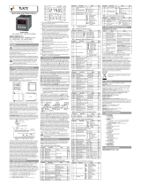
2. Descrizione strumento
I modelli TLK 48 B e TLK72 B sono dei regolatori digitali a microprocessore “sin-
gle loop”, con regolazione ON/OFF, ON/OFF a Zona Neutra, PID a singola azione
o PID a doppia azione (diretta e inversa) e con funzione di
AUTOTUNING FAST
o
OSCILLATORIO
per la regolazione PID. Il valore di processo viene visualizzato su 4
display rossi mentre lo stato delle uscite viene segnalato da 2 led. L’apparecchio
può avere sino a 2 uscite a relè o per il pilotaggio di relè statici (SSR) e dispone
inoltre di un indicatore di scostamento programmabile costituito da 3 led. In fun-
zione della sonda che si desidera collegare all’ingresso sono disponibili 4 modelli:
C: Per termocoppie (J, K, S e Sensori ad infrarosso ZIS), segnali in mV
(0... 50/60 mV, 12... 60 mV) e termoresistenze Pt100;
E: Per termocoppie (J, K, S e Sensori ad infrarosso ZIS), segnali in mV
(0... 50/60 mV, 12... 60 mV) e termistori PTC o NTC;
I: Per segnali analogici normalizzati 0/4... 20 mA;
V: Per segnali analogici normalizzati 0... 1 V, 0/1... 5 V, 0/2... 10 V.
TLK72B
11
2
1
7
10
8
3
4
9
6
5
AT
ST
TLK48B
Out2Out1
-=+
SET
11
2
1
7
6
10
8
3
4
9
5
1.
:
Utilizzato per accedere alla programmazione dei parametri di funziona-
mento e per confermare la selezione.
2.
:
Utilizzato per il decremento dei valori da impostare e per la selezione dei
parametri. Se mantenuto premuto consente inoltre di passare al precedente
livello di programmazione sino ad uscire dalla modalità di programmazione.
3.
: Utilizzato per l’incremento dei valori da impostare e per la selezione dei
parametri. Se mantenuto premuto consente inoltre di passare al precedente
livello di programmazione sino ad uscire dalla modalità di programmazio-
ne. Quando non ci si trova in modalità di programmazione consente di
visualizzare la potenza di regolazione in uscita.
4.
: Tasto dal funzionamento programmabile tramite il parametro USrb.
Può essere configurato per: Attivare Autotuning o Selftuning, Mettere lo
strumento in regolazione manuale, Tacitare l’allarme, Cambiare il Set Point
attivo, Disattivare la regolazione. Quando ci si trova nel menu ConF può
essere utilizzato per modificare la visibilità dei parametri.
5.
OUT1: Stato dell’uscita OUT1.
6.
OUT2: Stato dell’uscita OUT2.
7.
SET: Indica l’ingresso nella modalità di programmazione e il livello di
programmazione dei parametri.
8.
AT/ST: Indica la funzione Selftuning inserita (acceso) o Autotuning in
corso (lampeggiante).
9.
LED -: Indica che il valore di processo è inferiore rispetto al Set del valore
impostato al parametro [
SP - AdE]
.
10.
LED =:
Indica che il valore di processo è all’interno del campo
[SP + AdE... SP - AdE].
11.
LED +: Indica che il valore di processo è superiore rispetto al Set del
valore impostato al parametro [
SP + AdE]
.
3. Programmazione
Impostazione rapida dei set point - Questa procedura permette di impostare
in modo veloce il Set Point (SP1)ed eventualmente la soglia di allarme (Al1).
Premere il tasto
quindi rilasciarlo e il display visualizzerà SP1 e il valore
impostato. Per modificarlo agire sui tasti
per incrementare il valore o
per
decrementarlo. Una volta impostato il valore desiderato premendo il tasto
si
esce dalla modalità rapida di impostazione oppure si passa alla visualizzazione
delle soglie di allarme. L’uscita dal modo di impostazione rapida dei Set avviene
alla pressione del tasto
dopo la visualizzazione dell’ultimo Set oppure auto-
maticamente non agendo su alcun tasto per circa 15 secondi, trascorsi i quali il
display tornerà al normale modo di funzionamento.
Selezione degli stati di regolazione e programmazione dei para-
metri - Premendo il tasto
e mantenendolo premuto per circa 2 s si accede
al menu di selezione principale. Mediante i tasti
o
è possibile quindi
scorrere le selezioni:
OPEr
Menu parametri operativi:
contiene normalmente solo i parametri di
impostazione del Set point SP1 e della soglia di allarme AL1 ma può
contenere tutti i parametri desiderati (vedi par. 2.3).
ConF
Menu parametri di configurazione:
contiene tutti i parametri operativi e i
parametri di configurazione.
Oltre 2 s
USCITA
Menu
OPEro
conF
Gruppo
precedente
Gruppo
successivo
2 s
Parametro
precedente
Gruppi parametri Parametri Impostazione
Parametro
successivo
2 s
Incrementa
valore
Decrementa
valore
sp. sp1 1
Per accedere al menu ConF selezionare l’opzione ConF e premere il tasto ,
il display mostrerà 0. A questo punto impostare, coi tasti
e , il numero
riportato all’ultima pagina di questo manuale e premere il tasto
. Se si
imposta una password errata lo strumento ritorna nello stato di regolazione in
cui si trovava precedentemente. Se la password è corretta il display visualizzerà
il codice che identifica il primo gruppo di parametri (]SP) e con i tasti e
sarà possibile selezionare il gruppo di parametri che si intende editare.
Una volta selezionato il gruppo di parametri desiderato, premendo
verrà
visualizzato il codice che identifica il primo parametro del gruppo selezionato.
Coi tasti
e
si selezioni il parametro desiderato e, premendo il tasto
il
display visualizzerà il codice del parametro e la sua impostazione che potrà essere
modificata coi tasti
e
. Impostato il valore desiderato premere nuovamente
il tasto
: il nuovo valore verrà memorizzato e il display mostrerà nuovamente
la sigla del parametro selezionato. Coi tasti
e
è possibile selezionare
un altro parametro del gruppo (se presente) e modificarlo come descritto. Per
tornare a selezionare un altro gruppo di parametri mantenere premuto
o
per circa 2 s trascorsi i quali il display tornerà a visualizzare il codice del gruppo
di parametri. Quando questo accade rilasciare il tasto premuto e coi tasti
e
sarà possibile selezionare un altro gruppo ed accedere ai suoi parametri come
descritto precedentemente. Per uscire dal modo di programmazione non agire su
alcun tasto per circa 20 secondi, oppure mantenere premuto il tasto
o
oltre
2 secondi sino ad uscire dalla modalità di programmazione.
Le modalità di programmazione e di uscita dalla programmazione del menu
oPEr sono le stesse descritte per il menu ConF con la differenza che per
accedere al menu oPEr non è richiesta la Password.
Lo strumento viene programmato in fabbrica con tutti i parametri, ad
eccezione del Set Pont SP1 e della soglia di allarme AL1, program-
mabili nel menu ConF allo scopo di prevenire errate programmazioni
accidentali da parte di utenti non esperti.
4. Parametri programmabili
Di seguito vengono descritti tutti i parametri di cui lo strumento può essere
dotato, si fa presente che alcuni di essi potranno non essere presenti o perchè
dipendono dal tipo di strumento utilizzato o perché sono automaticamente
disabilitati in quanto parametri non necessari.
]
SP -
(parametri relativi al Set Point)
Parametro Descrizione Campo Def.
1 SP1 Set Point 1 SPLL... SPHL -1999
2 SPLL Set Point min. -1999... SPHL 0
3 SPHL Set Point max. SPLL... 9999 1
]
inP - (parametri relativi agli ingressi di misura)
Parametro Descrizione Campo Def.
4 SEnS
Input C
J/CrAL/ S/ Ir.J/ Ir.CA/
Pt1/
0.50/ 0.60/ 12.60
J
Input E
J/ CrAL/S/Ir.J/Ir.CA/Ptc/
ntc/0.50/0.60/12.60 (*)
Ptc
Input I 0.20/4.20 mA 4.20
Input V
0.1/0.5/1.5/0.10/2.10 V
0.10
5 SSC
Limite inferiore scala
ingresso segnali V/I
-1999... FSC 0
6 FSC
Limite superiore scala
ingresso segnali V/I
SSC... 9999 100
7 dP N° di decimali
Pt1/Ptc/ntc: 0/1;
Segnali norm.: 0... 3.
0
8 Unit
Unità di misura
temperatura
°C/°F °C
9 FiL Filtro digitale ingresso OFF... 20.0 s 1.0
10 OFSt Offset misura -1999... +9999 0
11 rot
Rotazione della retta
di misura
0.000... 2.000 1.000
12 OPE
Potenza in uscita
in caso di errore di
misura
-100... +100% 0
*
Ptc
= Termistore PTC KTY81-121,
ntc
= termistore NTC 103-AT2.
]
Out - (parametri relativi alle uscite)
Parametro Descrizione Campo Def.
13 O1F
Funzione
uscita 1
1.rEG = Uscita di regolazione 1;
2.rEG = Uscita di regolazione 2;
ALno = Uscita di allarme NA;
ALnc = Uscita di allarme NC;
ALni = Uscita di allarme NC con
funzionamento negato del led.
1.rEG
14 O2F
Funzione
uscita 2
ALno
]
AL1 - (parametri relativi all’allarme AL1)
Parame-
tro
Descrizione Campo Def.
15 OAL1 Uscita AL1 Out1/Out2//OFF Out2
16 AL1t Tipo allarme AL1
LoAb = Assoluto di min.;
HiAb = Assoluto di max.;
LHAb = Finestra assoluta;
LodE = Relativo di min.;
HidE = Relativo di max.;
LHdE = Finestra relativa.
LoAb
17 AL1 Soglia AL1 AL1L... AL1H 0
18 AL1L
Soglia inferiore AL1 a
finestra o limite infe-
riore AL1 per allarmi di
minima o massima
-1999... AL1H -1999
19 AL1H
Soglia superiore
AL1 a
finestra o
limite supe-
riore
AL1
per allarmi di
minima o massima
AL1L... 9999 9999
20 HAL1 Isteresi AL1 OFF... 9999 1
21 AL1d Ritardo attivazione AL1 OFF... 9999 s OFF
22 AL1i
Attivazione AL1
in caso
di errore di misura
no/yES no
]
rEG
- (parametri relativi alla regolazione)
Parametro Descrizione Campo Default
23 Cont Tipo di regolazione
Pid = PID;
On.FA = ON/OFF asimm.;
On.FS = ON/OFF simm.;
nr = ON/OFF a Zona
Neutra.
1
24 Func Funz.uscita 1.rEg
HEAt = Riscalda;
CooL = Raffredda.
HEAt
25 HSEt
Isteresi regolazione ON/OFF
0... 9999 1
26 CPdt
Tempo ritardo protez.
compressore 2.rEG
OFF... 9999 s OFF
27 Auto
Abilitazione autotuning
Fast
OFF = Diabilitato;
1 = All’accensione;
2 = Alla 1ª accensione;
3 = Avvio manuale;
4 = Avvio al cambio di SP.
OFF
28 A.SEL Tipo di autotuning
FASt = FAST
OSC = Oscillating
FASt
29 Pb Banda proporzionale 0... 9999 40
30 Int Tempo integrale OFF... 9999 s 300
31 dEr Tempo derivativo OFF... 9999 s 30
32 FuOc Fuzzy overshoot control 0.00... 2.00 0.50
33 tcr1
Tempo di ciclo uscita 1.rEg
0.1... 130.0 s 20.0
34 Prat
Rapporto potenza
2.rEg/1.rEg
0.01... 99.99 1.00
35 tcr2
Tempo di ciclo uscita 2.rEg
0.1... 130.0 s 10.0
36 rS Reset manuale -100... +100% 0.0
37 SLor
Velocità rampa
InF = Rampa non attiva
0.00... 99.99 unità/min
InF
]
PAn - (parametri interfaccia operatore)
Parametro Descrizione Campo Default
72 AdE Valore di sco
stamento
OFF... 9999
(TLK48)
2
5. Problemi, manutenzione e garanzia
Segnalazioni di errore
Errore Motivo Azione
----
Interruzione sonda
Verificare la corretta connessio-
ne della sonda con lo strumento
e quindi verificare il corretto
funzionamento della sonda
uuuu
Misura sotto i limiti della
sonda (underrange)
oooo
Misura sopra i limiti della
sonda (overrange)
ErAt
Autotuning non eseguibile
perchè non sono veri-
ficate le condizioni per
poterlo avviare
Premere il tasto
per far scom-
parire l’errore. Provare quindi a
ripetere l’autotuning quando le
condizioni lo permettono.
noAt
Autotuning non termina-
to entro 12 ore
Provare a ripetere l’autotuning
dopo aver controllato il funziona-
mento della sonda e dell’attuatore
ErEP
Possibile anomalia nella
memoria EEPROM
Premere il tasto
Pulizia
- Si raccomanda di pulire lo strumento solo con un panno leggermente
imbevuto d’acqua o detergente non abrasivo e non contenente solventi.
Garanzia e riparazioni
- Lo strumento è garantito da vizi di costruzione o difetti
di materiale riscontrati entro 12 mesi dalla data di consegna. La garanzia si
limita alla riparazione o la sostituzione del prodotto. L’eventuale apertura del
contenitore, la manomissione dello strumento o l’uso e l’installazione non
conforme del prodotto comporta automaticamente il decadimento della garanzia.
In caso di prodotto difettoso in periodo di garanzia o fuori periodo di garanzia
contattare l’ufficio vendite Ascon Tecnologic per ottenere l’autorizzazione alla
spedizione. Il prodotto difettoso, quindi, accompagnato dalle indicazioni del
difetto riscontrato, deve pervenire con spedizione in porto franco presso lo
stabilimento Ascon Tecnologic salvo accordi diversi.
Smaltimento
L’apparecchiatura (o il
prodotto) deve essere
oggetto di raccolta separata in conformità alle
vigenti normative locali in materia di smaltimento.
6. Dati tecnici
Alimentazione: 24 VAC/VDC, 100... 240 VAC ±10%, 50/60 Hz;
Assorbimento: 4 VA circa;
Ingresso: 1 ingresso per sonde di temperatura: tc J, K, S, sensori all’infrarosso
AT ZIS J e K; RTD Pt 100 IEC; PTC KTY 81-121 (990W @ 25°C); NTC 103AT-2
(10kW @ 25°C), segnali in mV 0... 50 mV, 0... 60 mV, 12... 60 mV o segnali
normalizzati 0/4... 20 mA, 0... 1 V, 0/1... 5 V , 0/2... 10 V;
Impedenza ingresso segnali normalizzati: 0/4... 20 mA: 51W; mV e V: 1 MW;
Uscite: Sino a 2 uscite a relè SPDT (8 A-AC1, 3 A-AC3/250 VAC) o in tensione per
pilotaggio SSR (8 mA/8 VDC);
Uscita alimentazione ausiliaria: 10 VDC/20 mA max.;
Vita elettrica uscite a relè:
100000 operazioni;
Categoria di installazione:
II;
Categoria di misura:
I;
Classe di protezione contro le scosse elettriche:
Frontale in Classe II;
Isolamento
: Rinforzato tra parti in bassa tensione (alimentazione e uscite a relè)
e frontale; rinforzato tra parti in bassa tensione (alimentazione e uscite a relè) e
parti in bassissima tensione (ingresso, uscite statiche); nessun isolamento tra
ingresso e uscite statiche;
Contenitore:
Plastica autoestinguente UL 94 V0;
Dimensioni: TLK48 B:
48 x 48 mm DIN, profondità 98 mm,
TLK72 B:
72 x 72 mm DIN, profondità 97 mm;
Peso: TLK48 B:
150 g circa,
TLK72 B:
215 g circa;
Installazione: TLK48 B:
Incasso a pannello, foro 45 x 45 mm,
TLK72 B:
Incasso a pannello, foro 66.5 x 66.5 mm;
Connessioni: TLK48 B:
Morsettiera a vite 2 x 1 mm
2
,
TLK72 B:
Morsettiera a vite sconnettibile 2.5 mm
2
;
Grado di protezione frontale:
IP54 con guarnizione;
Grado di inquinamento:
2;
Temperatura ambiente di funzionamento:
0... 50°C;
Umidità ambiente di funzionamento:
30 ... 95 RH% senza condensa;
Temperatura di trasporto e stoccaggio:
-10... +60°C;
Regolazione:
ON/OFF, ON/OFF a Zona Neutra, PID a singola azione, PID a doppia
azione;
Campo di misura:
tc J (SEnS = J): 0... 1000°C/32... 1832°F,
tc K (SEnS = CrAl): 0 ... 1370°C/32 ... 2498°F,
tc S (SEnS = S): 0...1760°C/32...3200°F,
Pt100 IEC (SEnS = Pt1): -200... +850°C/-328... +1562°F,
PTC KTY81-121(SEnS = Ptc): -55... +150°C/-67... +302°F,
NTC 103-AT2 (SEnS = ntc): -50... +110°C/-58... +230°F;
Risoluzione visualizzazione:
Secondo la sonda utilizzata: 1/0.1/0.01/0.001;
Precisione totale:
±0.5% fs (tc S: ±1% fs);
Tempo di campionamento misura:
130 ms;
Display:
TLK48 B:
4 Digit Rosso h 12 mm.
TLK72 B:
4 Digit Rosso h 14 mm;
Conformità:
Direttiva CEE EMC 2004/108/CE (EN 61326),
Direttiva CEE BT 2006/95/CE (EN 61010-1);
Omologazioni:
C-UL (file n. E206847).
7. Codifica dello strumento
TLK48/TLK72 a b c d e f g hh B
a
: ALIMENTAZIONE
L
= 24 VAC/VDC;
H
= 100... 240 VAC.
b
: INGRESSO
C
= Termocoppie (J, K, S, I.R.), mV, termoresistenze (Pt100);
E
= Termocoppie (J, K, S, I.R.), mV, termistori (PTC, NTC);
I
= Segnali normalizzati 0/4... 20 mA;
V
= Segnali normalizzati 0... 1 V, 0/1... 5 V, 0/2... 10 V.
c
: USCITA OUT1
R
= Relè per carichi resistivi;
O
= VDC per SSR.
d
: USCITA OUT2
R
= Relè per carichi resistivi;
O
= VDC per SSR;
- = Non presente.
e
: CODICI NON DISPONIBILI;
f
: CODICI NON DISPONIBILI;
g
: CODICI NON DISPONIBILI;
hh
: CODICI SPECIALI.
8. Password di protezione
PASSWORD TLK48 B/TLK7 B = 381

TLK48 B - TLK72 B
ELECTRONIC DIGITAL CONTROLLER
Quick Guide
Cod.: ENG/ITA - Vr. 02 - 17/04 - ISTR-FTLK4872BIE02
ASCON TECNOLOGIC S.r.l.
Viale Indipendenza 56 - 27029 Vigevano (PV) ITALY
TEL.: +39 0381 69871 - FAX: +39 0381 698730
http:\\www.ascontecnologic.com
e-mail: [email protected]
Foreword
This manual contains the information necessary for the installation, use
and maintenance of the product, we therefore recommend that the utmost
attention is paid to the following instructions and to save it.
This document is exclusive property of Ascon Tecnologic which forbids any repro-
duction and divulgation, even in part, of the document, unless expressly authorized.
Ascon Tecnologic
reserves the right to make any formal or functional changes at
any moment and without any notice.
Ascon Tecnologic
and its legal representatives do not assume any responsibility
for any damage to people, things or animals deriving from violation, wrong or
improper use or in any case not in compliance with the instrument’s features.
Whenever a failure or a malfunction of the device may cause danger-
ous situations for persons, thing or animals, please remember that the
plant has to be equipped with additional devices which will guarantee
safety.
For more information download the detailed operating instruction manual from:
www.ascontecnologic.com
1. Installation and use warnings
Permitted use
- The instrument has been projected and manufactured as
a measuring and control device to be used according to EN61010-1 for the
altitudes operation until 2000 ms. The use of the instrument for applications not
expressly permitted by the above mentioned rule must adopt all the necessary
protective measures.
The instrument CANNOT be used in dangerous environments (flammable or explo-
sive) without adequate protection. The installer must ensure that EMC rules are
respected, also after the instrument installation, if necessary using proper filters.
Mechanical mounting
TLK48 B - The instrument, in case 48 x 48 mm, is designed for flush-in panel
mounting. Make 45 x 45 mm a hole and insert the instrument, fixing it with the
provided special brackets. We recommend that the gasket is mounted in order
to obtain the declared front protection degree.
98
44.5
9.5
TLK4_
48
48
Panel + Gasket
max. 9 mm
Bracket type 1 Bracket type 2
45
45
TLK72 B - The instrument, in case 72 x 72 mm, is designed for flush-in panel
mounting. Make a 66.5 x 66.5 mm hole and insert the instrument, fixing it with
the provided special brackets. We recommend that the gasket is mounted in
order to obtain the declared front protection degree.
71
88
65.5
8
72
72
55
Panel + Gasket max. 5 mm
65.5
65.5
Brackets
General installation warnings -
Avoid placing the instrument in environ-
ments with very high humidity levels or dirt that may create condensation or intro-
duction of conductive substances into the instrument. Ensure adequate ventilation
to the instrument and avoid installation in containers that house devices which may
overheat or which may cause the instrument to function at a higher temperature
than the one permitted and declared.
Connect the instrument as far away as possible from sources of electromagnetic
disturbances such as motors, power relays, relays, solenoid valves, etc..
Electrical connections - Carry out the electrical wiring by connecting only one
wire to each terminal, according to the following diagram, checking that the power
supply is the same as that indicated on the instrument and that the load current
absorption is no higher than the maximum electricity current permitted.
TLK48 B
NO
(max. 20 mA)
NTC/PTC
I
+
ext.
gen.
+
+
-
OUT 12 VDC
SUPPLY
4... 20 mA PASSIVE (2 wires)
4... 20 mA ACTIVE
4
Pt100
TC
INPUT
2
+
1 3
-
75 6 8
C
910
OUT2
NO
11
C
12
OUT1
+
-
+
-
+
+
-
+
-
+
-
SSR: 8 mA/8 VDC
Relays: 8A-AC1 (3A-AC3) 250VAC
4... 20 mA ACTIVE
0... 50/60 mV, 0... 1 V, 0/1... 5 V, 0/2... 10 V
TLK72 B
0... 50/60 mV; 0...1 V; 0/1...5 V; 0/2...10 V
0/4... 20 mA ACTIVE
C
OUT1
2122 20
+
Pt100
TC
-
+
1 23
PTC-NTC
-
+
+
+
-
gen.
ext.
+
I
+
+
-
-
NOC
13
SUPPLY
18
OUT2
19 17 16 15 14 12
4... 20 mA ACTIVE
54 678
OUT 12 VDC (max. 20 mA)
NC NO
+
-
+
4... 20 mA PASSIVE (2 wires)
SSR: 8 mA/8 VDC
Relays: 8A-AC1 (3A-AC3) 250VAC
As the instrument is built-in equipment with permanent connection inside
housing, it is not equipped with either switches or internal devices to protect
against overload of current: the installation will include an overload protection
and a two-phase circuit-breaker, placed as near as possible to the instrument
and located in a position that can easily be reached by the user and marked
as instrument disconnecting device which interrupts the power supply to the
equipment. It is also recommended that the supply of all the electrical circuits
connected to the instrument must be protect properly, using devices (ex. fuses)
proportionate to the circulating currents.
It is strongly recommended that cables with proper insulation, according to the
working voltages and temperatures, be used. Furthermore, the input cable of the
probe has to be kept separate from line voltage wiring. If the input cable of the
probe is screened, it has to be connected to the ground with only one side. We
recommend that a check should be made that the parameters are those desired
and that the application functions correctly before connecting the outputs to the
actuators so as to avoid malfunctioning that may cause irregularities in the plant
that could cause damage to people, things or animals.
2. Instrument description
TLK48 B and TLK72 B are digital microprocessor-based controllers, with ON/OFF,
Neutral Zone ON/OFF, PID single action, PID dual action (direct and reverse)
control and with
AUTOTUNING
function (FAST or OSCILLATING type).
The instrument can have up to 2 outputs: relay type or can drive solid state relays
type (SSR). Depending on the model required the input accept:
C: Thermocouples temperature probes (J, K, S and ZIS Infrared sensors),
mV signals (0... 50/60 mV, 12... 60 mV) and Pt100 thermoresistances;
E: Thermocouples temperature probes (J, K, S and ZIS Infrared sensors),
mV signals (0... 50/60 mV, 12... 60 mV) and PTC or NTC Thermistors;
I: Normalized analogue signals 0/4... 20 mA;
V: Normalized analogue signals 0... 1 V, 0/1... 5 V, 0/2... 10 V.
TLK72B
11
2
1
7
10
8
3
4
9
6
5
AT
ST
TLK48B
Out2Out1
-=+
SET
11
2
1
7
6
10
8
3
4
9
5
1.
: Key to access the programming parameters and confirm the selection.
2.
: Key to decrease the values to be set and to select the parameters.
If the key is held down, the user returns to the previous programming level until
he exits the programming mode.
3.
: Key to increase the values to be set and to select the parameters. If
the key is held down, the user returns to the previous programming level
until he exits the programming mode. Outside the programming mode it
permits visualisation of the output control power.
4.
:
It can be set to
Activate Auto-tuning and Self-tuning functions and
modify the visibility of the parameters in ConF menu.
5.
OUT1: Indicates the state of output OUT1.
6.
OUT2: Indicates the state of output OUT2.
7.
SET: It indicates access to the programming mode and parameter
programming level.
8.
AT/ST: Indicates that Auto-tuning is in progress (flashing).
9. LED -
: Indicates that the process value is lower than [SP - AdE].
10. LED =
: Indicates that the process value is inside the range
[SP + AdE... SP - AdE].
11. LED +
: indicates that the process value is higher than [SP + AdE].
3. Controller Programming
Set Point Quick Setup - This procedure allows the fast programming of the
active Set Point (SP1) and eventually the alarm threshold (AL1). Push key
, then
release it, the display shows SP1 and its programmed value; to modify it, press
to increase the value or key to decrease it. These keys change the value one
digit at a time, but if they are pressed for more than one second, the value increases
or decreases rapidly, then, after two seconds in the same condition, the changing
speed further increases in order to rapidly reach the desired value. Once the desired
value has been reached, pushing key it is possible to exit the Quick Setup mode
or (if the instrument have an output configured as alarm) is possible to display
and modify the alarm threshold in sthe same way as SP1. To exit the Set Point
Quick Setup it is necessary to press after the visualisation of the last Set Point,
or alternatively pressing no keys for about 15 seconds the display automatically
returns to normal functioning. Set Point SP1 can be programmed with a value that
is between the value programmed between the parameters SPLL and SPHL.
Parameters programming - By pushing key
and holding it down for
about 2 s it is possible to enter into the main selection menu. Using the
or
keys, it is then possible to roll over the selections:
OPEr
Operating parameters Menu
: this normally contains the Set Point “SP1”
and the alarm threshold “AL1” parameters but it can contain all the
desired parameters (see par. 2.3).
ConF
Configuration parameters Menu
: this contains all the operating param-
eters and the functioning configuration parameters.
More than 2 s
EXIT
OPEr
or
conF
Menu
Previous
Group
Next
Group
2 s
Previous
Parameter
Parameter Groups Parameters Set Parameters
Next
Parameter
2 s
Increase
value
Decrease
value
or
or
sp. sp1 1
To enter the ConF menu select the option ConF, press the key , the display
shows 0. At this request, enter, using keys and , the number reported
on the last page of this manual and push key
. If an incorrect password
is entered, the instrument exit from programming mode. If the password is
correct, the display shows the code that identifies the first group of parameters
(]SP) and with keys
and it will be possible to select the desired group of
parameters. Once the desired group of parameters has been selected, the code
identifying the first parameter of the selected group will be visualised by pushing
the
key. Again using the and keys, it is possible to select the desired
parameter and, if the key
is pressed, the display will alternatively show the
parameter code and its programming value, which can be modified by using the
/ keys. Once the desired value has been programmed, push key once
more: the new value will be memorised and the display will show only the code
of the selected parameter. By using the
/ keys, it is then possible to select
a new parameter (if present) and modify it as described above.
To select another group of parameters, keep the
/ key pressed for about 2
s, afterwards the display will return to visualise the code of the group of param-
eters. Release the key and by using the
and keys, it will be possible to
select a new group . To exit the programming mode, no key should be pressed
for about 20 s, or keep the
/ pressed until exit from the programming
mode is obtained. The programming and exit modes for the OPEr menu are the
same as those described for menu ConF with the difference that to access the
menu OPEr the Password is not required.
The instrument is factory programmed with all the parameters, with
the exception of SP1 Set Point and AL1 alarm threshold, programma-
ble in the menu ConF. This has be done with the purpose to prevent
wrong accidental programming from non experienced consumers.
4. Programmable parameters
Below are described all the parameters available in the instrument. Some
of them could be not present either because they are instrument depend or
because they are automatically disabled as unnecessary.
]
SP Group -
(Set Points parameters)
Parameter Description Range Def.
1 SP1 Set Point 1 SPLL... SPHL 0
2 SPLL Set Point min. -1999... SPHL -1999
3 SPHL Set Point max. SPLL... 9999 9999
]
inP
Group
- (measuring inputs parameters)
Parameter Description Range Def.
4 SEnS
Input C
J/CrAL/ S/ Ir.J/ Ir.CA/
Pt1/ 0.50/ 0.60/ 12.60
J
Input E
J/ CrAL/S/Ir.J/Ir.CA/Ptc/
ntc/0.50/0.60/12.60 (*)
Ptc
Input I 0.20/4.20 mA 4.20
Input V
0.1/0.5/1.5/0.10/2.10 V
0.10
5 SSC
Low scale limit for V/I
signals
-1999... FSC 0
6 FSC
High scale limit for V/I
signals
SSC... 9999 100
7 dP Number of decimals
Pt1/Ptc/ntc: 0/1;
Norm. signals: 0... 3.
0
8 Unit Temperature unit °C/°F °C
9 FiL Input digital filter OFF... 20.0 s 1.0
10 OFSt
Measuring Offset
-1999... +9999 0
11 rot
Rotation of the measuring
straight line
0.000... 2.000 1.000
12 OPE
% power in case of
measuring error
-100... +100% 0
* Ptc = PTC KTY81-121 thermistor,
ntc = NTC 103-AT2 thermistor.
]
Out
Group
- (Outputs parameters)
Parameter Description Range Def.
13 O1F Out 1 function
1.rEG
= Control output 1;
2.rEG
= Control output 2;
ALno
= NO Alarm output;
ALnc
= NC Alarm output;
ALni
= NC Alarm output,
reversed led functioning.
1.rEG
14 O2F O2F ALno
]
AL1
Group
- (AL1 parameters)
Parameter Description Range Def.
15 OAL1 AL1 Output Out1/Out2//OFF Out2
16 AL1t AL1 type
LoAb = Absolute Low;
HiAb = Absolute High;
LHAb = Absolute Band;
LodE = Deviation Low;
HidE = Deviation High;
LHdE = Deviation Band,
LoAb
17 AL1 AL1 threshold AL1L... AL1H 0
18 AL1L
Low threshold band alarm
AL1 or min. set alarm AL1
for high or low alarm
-1999... AL1H -1999
19 AL1H
High threshold band alarm
AL1 or max. set alarm AL1
for high or low alarm
AL1L... 9999 9999
20 HAL1 AL1 hysteresis OFF... 9999 1
21 AL1d AL1 delay OFF... 9999 s OFF
22 AL1i
AL1 activation at measur-
ing error
no/yES no
]
rEG
Group
- (Control parameters)
Parameter Description Range Def.
23 Cont Control type
Pid = PID;
On.FA = Asymm. ON/OFF;
On.FS = Symm. ON/OFF;
nr = Neutral Zone ON/OFF.
PID
24 Func
Functioning mode
output 1.rEG
HEAt;
CooL.
HEAt
25 HSEt
Hysteresis of ON/OFF
control
0... 9999 1
26 CPdt
Compressor protection
time for 2.rEG
OFF... 9999 s OFF
27 Auto Autotuning
Fast
enable
OFF = Not active;
1 = Start at power ON;
2 = At 1
st
power ON;
3 = Start manually;
4 = Start after SP change.
OFF
28 A.SEL Autotuning mode
FASt = FAST
OSC = Oscillating
FASt
29 Pb Proportional Band 0... 9999 40
30 Int Integral time OFF... 9999 s 300
31 dEr Derivative time OFF... 9999 s 30
32 FuOc
Fuzzy overshoot control
0.00... 2.00 0.50
33 tcr1
Output cycle time 1.rEg
0.1... 130.0 s 20.0
34 Prat
Power ratio 2.rEg/1.rEg
0.01... 99.99 1.00
35 tcr2
Output cycle time 2.rEg
0.1... 130.0 s 10.0
36 rS Manual Reset -100... +100% 0.0
37 SLor
Ramp gradient
InF = Ramp not active
0.00... 99.99 unit/min
InF
]
PAn
Group
- (user interface parameters)
Parameter Description Range Def.
72 AdE
Shift value
OFF... 9999
(TLK48)
2
5. Problems, maintenance and warranty
Error messages
Error Reason Action
----
Probe interrupted
Verify the correct connection
between probe and instru-
ment and then verify the cor-
rect functioning of the probe
uuuu
Measured variable under the
probe limits (underrange)
oooo
Measured variable over the
probe limits (overrange)
ErAt
Auto-tuning not possible
because the process value
is too high or low
Press
key in order to erase
the error message. Once the
error has been found, try to
repeat the auto-tuning process
noAt
Auto-tuning not finished
within 12 hours
Check the functioning of probe
and actuator and try to repeat
the auto-tuning
process
ErEP
Possible anomaly of the
EEPROM memory
Press
key
Cleaning
- Clean the instrument with a slightly wet cloth using water and not
abrasive cleaners or solvents which may damage the instrument.
Warranty and repairs
- This product is under warranty against manufacturing
defects or faulty materials that are found within 18 months from delivery date.
The warranty is limited to repairs or to the instrument replacement. The tamper-
ing of the instrument or an improper use of the product will bring about the
immediate withdrawal of the warranty effects. In the event of a faulty instrument,
either within the period of warranty, or further to its expiry, please contact our
sales department to obtain authorisation for sending the instrument to our com-
pany. The faulty product must be shipped to Ascon Tecnologic with a detailed
description of the faults found, with no fee or charge for Ascon Tecnologic,
except in the event of alternative agreements.
Disposal
The appliance (or the product) must be disposed
of separately in compliance with the local standards
in force on waste disposal.
6. Technical data
Power supply:
24 VAC/VDC, 100... 240 VAC ±10%, 50/60 Hz;
Power consumption:
About 4 VA;
Input: 1 input for temperature probes: tc J, K, S, infrared sensors AT ZIS J and K;
RTD Pt 100 IEC; PTC KTY 81-121 (990W @ 25°C); NTC 103AT-2 (10kW @ 25°C),
signals in mV: 0... 50 mV, 0... 60 mV, 12... 60 mV or
normalized signals 0/4... 20 mA,
0... 1 V, 0/1... 5 V , 0/2... 10 V;
Normalized signals impedance: 0/4... 20 mA: 51W; mV and V: 1 MW;
Outputs: Up to 2 outputs: Relays SPDT (8 A-AC1, 3 A-AC3/250 VAC)
or voltage
outputs to drive SSR (8 mA/8 VDC);
Auxiliary supply output:
10 VDC/20 mA max.;
Relay electrical life:
100000 operations;
Installation category:
II;
Measurement category:
I;
Protection class against electric shock:
Class II for Front panel;
Insulation: Reinforced insulation between the low voltage section (supply and relay
outputs) and the front panel; Reinforced insulation between the low voltage section
(supply and relay outputs) and the extra low voltage section (inputs, SSR outputs);
No insulation between input and SSR outputs;
Housing:
Self-extinguishing plastic UL 94 V0;
Dimensions: TLK48 B:
48 x 48 mm DIN, depth 98 mm,
TLK72 B:
72 x 72 mm DIN, depth 97 mm;
Weight:
TLK48 B:
about 150 g,
TLK72 B:
about 215 g;
Mounting:
TLK48 B:
Flush in panel in 45 x 45 mm hole,
TLK72 B:
Flush in panel in 66.5 x 66.5 mm hole;
Connections:
TLK48 B:
2 x 1 mm
2
screw terminals block,
TLK72 B:
Extractable 2.5 mm
2
screw terminal block;
Front protection:
IP54 mounted in panel with gasket.
Pollution degree:
2;
Operating temperature:
0... 50°C;
Operating humidity:
30... 95 RH% with no condensation;
Storage temperature:
-10... +60°C;
Control:
ON/OFF, ON/OFF Neutral Zone, PID single and double action;
Measurement range:
tc J (SEnS = J): 0... 1000°C/32... 1832°F,
tc K (SEnS = CrAl): 0 ... 1370°C/32 ... 2498°F,
tc S (SEnS = S): 0...1760°C/32...3200°F,
Pt100 IEC (SEnS = Pt1): -200... +850°C/-328... +1562°F,
PTC KTY81-121(SEnS = Ptc): -55... +150°C/-67... +302°F,
NTC 103-AT2 (SEnS = ntc): -50... +110°C/-58... +230°F;
Display resolution:
According to the probe used: 1/0.1/0.01/0.001;
Overall accuracy:
±0.5% fs (tc S: ±1% fs);
Sampling rate:
130 ms;
Display:
TLK48 B:
4 Digit Red h 12 mm,
TLK72 B:
4 Digit Red h 14 mm;
Compliance:
ECC directive EMC 2004/108/CE (EN 61326),
ECC directive LV 2006/95/CE (EN 61010-1);
Approvals:
C-UL (file n. E206847)
7. How to order
TLK48/TLK72 a b c d e f g hh B
a
: POWER SUPPLY
L
= 24 VAC/VDC;
H
= 100... 240 VAC.
b
: INPUT
C
= Thermocouples (J, K, S, I.R.), mV, thermoresistances (Pt100);
E
= Thermocouples (J, K, S, I.R.), mV, thermistors (PTC, NTC);
I
= Normalized signals 0/4... 20 mA;
V
= Normalized signals 0... 1 V, 0/1... 5 V, 0/2... 10 V.
c
: OUTPUT OUT1
R
= Relay for resistive loads;
O
= VDC for SSR.
d
: OUTPUT OUT2
R = Relay for resistive loads;
O = VDC for SSR;
- = None.
e
: UNAVAILBLE CODES;
f
: UNAVAILBLE CODES;
g
: UNAVAILBLE CODES;
hh
: SPECIAL CODES.
8. Protection Password
TLK48 B/TLK72 B PASSWORD = 381
-
 1
1
-
 2
2


ASCON TECNOLOGIC S.r.l. TLK72 B Quick Manual
- Tipo
- Quick Manual
- Questo manuale è adatto anche per
in altre lingue
- English: ASCON TECNOLOGIC S.r.l. TLK72 B
Documenti correlati
Altri documenti
-
Ascon tecnologic TLK38 Manuale del proprietario
-
-
-
-
-
-
-
Ascon tecnologic TLK94 Manuale del proprietario
-
-