Pulsar Trail 2 LRF Manuale del proprietario
- Tipo
- Manuale del proprietario

OPERATING INSTRUCTIONS
TRAIL 2 LRF
Thermal Imaging
Riescopes
ENGLISH / FRANÇAIS / DEUTSCH / ESPAÑOL / ITALIANO / РУССКИЙ


ENGLISH
Technical Specications
MODEL TRAIL 2 LRF XQ50 XP50
SKU 76518 76519
MICROBOLOMETER
Type uncooled
Resolution, Pixels 384х288 640x480
Frame Rate, Hz 50
Pixel Pitch, µm 17
OPTICAL CHARACTERISTICS
Objective Lens F50 mm, F/1.2
Magnication, x 3.5 2
Digital Zoom, x 3.5-14 2-16
Discrete Digital Zoom x2/x4 х2/x4/x8
Eye Relief, mm 50
Field of View (H), °
m@100m
7.5
13.1
12.4
21.8
Diopter Adjustment, D +3/-5
Range of Detection, (Deer Type Object), m/y 1800/1968
Minimum Focusing Distance, m / y 5 / 5.5
RETICLE
Click Value, mm@100 m (H/V) 13/13 21/21
Click Range, mm@100 m (H/V) 2600/2600 4200/4200
DISPLAY
Type AMOLED
Resolution, Pixels 1024х768
POWER SUPPLY
Battery Type / Capacity / Output Voltage Li-Ion Battery Pack IPS7 / 6400 mAh / DC 3.7 V
Power Supply 3-4.2 V
External Power Supply 5 V (USB)
OPERATIONAL CHARACTERISTICS
Max. Operating Time on Battery Pack (at t=22°C), Hours* 8
Max. Recoil Power on Ried Weapon, Joules 6000
Max. Recoil Power on Smooth-Bore Weapon, Caliber 12
Level of Protection (acc. to IEC 60529) IPX7
Operating Temperature, °C / °F -25…+50 / -13…+122
Dimensions (LxWxH), mm
inch
347х102х74
13.66х4.02х2.91
351х102х74
13.82х4.02х2.91
Weight (w/o Batteries, Mount), kg
oz
0.8
28.22
VIDEO RECORDER
Video / Photo Resolution, Pixels 1024x768
Video / Photo Format .mp4 / .jpg
Built-In Memory 16 GB
Built-In Memory Capacity About 5 h video or > 100 000 pictures
MODEL TRAIL 2 LRF XQ50 XP50
Frequency 2.4 GHz
Standard 802.11 b/g
Line-of-Sight Reception Range, m 15
CHARACTERISTICS OF THE RANGEFINDER
Wavelength, nm 905
Measurement Range, m/y** 1000/1094
Measurement Accuracy, m +/-1
* The actual operating time depends on the intensity of using Wi-Fi, video recorder, laser rangender.
** Depends on the characteristics of the object under observation and environmental conditions.
1. Package Contents
•
Thermal Imaging Riescope
•
IPS7 Battery Pack
•
Battery charger with mains charger
•
Carrying case
•
MicroUSB cable
•
Mount (with screws and hex-nut wrench(-es))*
•
Quick start guide
•
Lens cloth
•
Warranty card
* The mount may not be included in certain orders.
This product is subject to change in line with improvements to its design.
The latest edition of this user manual is available online at www.pulsar-vision.com
2. Description
Thermal imaging riescopes TRAIL 2 LRF are designed for the use on hunting ries, both in the nighttime,
and in the daylight in inclement weather conditions (fog, smog, rain) to see through obstacles hindering
detection of targets (branches, tall grass, thick bushes etc.). Unlike the image intensier tube based night
vision riescopes, thermal imaging riescopes do not require an external source of light and are not affected
by bright light exposure. TRAIL 2 LRF riescopes are equipped with a high precision built-in laser rangender
which allows distance measurement up to 1000 meters. The TRAIL 2 LRF riescopes have a wide range of
applications including night hunting, observation and terrain orientation, search and rescue operations.
1

3. Features
•
Built-in precise laser rangender
•
High resolution thermal imaging microbolometer
•
Rugged and light-weight magnesium alloy housing
•
Long detection distance up to 1800 m
•
Smooth and discrete digital zoom
•
High caliber recoil resistance 12 gauge, 9.3x64, .375 H&H
•
High refresh rate 50 Hz
•
Zeroing proles memorization
•
Frost resistant AMOLED display
•
Built-in video recorder
•
Built-in Wi-Fi module
•
Quick-change long-life rechargeable battery packs
•
“Image Detail Boost” function
•
“Picture-in-Picture” mode
•
Manual contrast and brightness adjustment
•
Variable electronic reticles
•
Four operating modes: Forest, Rocks, Identication, User.
•
Three calibration modes
4. External View and Controls
1. Lens cover
2. Lens focusing knob
3. Button UP
4. Button MENU (M)
5. Button DOWN
6. Button REC
7. Diopter adjustment ring
8. Eyeshade
9. Laser rangender
9a. Laser rangender’s emitter
9b. Laser rangender’s receiver
10. MicroUSB port
11. Button ON
12. Battery Pack
13. Lever for Battery Pack
10
1 2
6
7
5
4
3
99b
9a
11
D
12
13
8
2

5. Description of Controls
Button Current operating
mode
First short press Other short presses Long press
ON (11)
Power riescope on Calibrate the microbolometer Turn display off/
Power riescope off
Turn display on Calibrate the microbolometer
Calibrate the microbolometer
UP (3)
Regular
(observation)
Activate rangender Switch color palettes
Distance measurement SCAN mode ON/OFF
Menu navigation
Navigation upwards/rightwards
–
MENU (4)
Regular
(observation)
Enter quick menu Enter main menu
Main menu
Conrm selection Exit submenu without con-
rming selection / Exit menu
(switch to viewing mode)
Quick menu
Switch between quick menu options
DOWN (5)
Regular
(observation)
Control discrete digital zoom
PiP on/off
Menu navigation
Navigation downwards/leftwards
–
REC (6)
Video mode
Start video
recording
Pause / resume video
recording
Stop video recording /
Switch to photo mode
Photo mode
Take a photograph Switch to video mode
6. Using the Battery Pack
Thermal imaging riescopes are supplied with a rechargeable Li-Ion Battery Pack IPS7 which allows operation
for up to 8 hours. Please remember to charge the Battery Pack before rst use.
Charging:
•
Lift lever (A) of the charger.
•
Remove protective cover from the Battery Pack.
•
Insert the battery into the charger, as shown in the gure, push the lever to full stop (A).
•
Upon installation, a green LED indicator (B) on the charger
will start to glow and begin ashing:
- once if the battery charge ranges from 0% to 50%;
- twice if the battery charge ranges from 51% to 75%;
- three times if the battery charge ranges from
75% to 100%;
•
If the indicator lights green continuously,
the battery is fully charged. You can
remove the battery from the charger by
lifting the lever.
•
To charge the battery, connect the Micro-
USB plug of the USB cable to port (C) of the
charger.
•
Connect the plug of the USB cable to the mains adapter.
•
Plug the mains adapter into a 100 - 240 V socket – the battery charging process will start.
Attention! If the indicator of the charger lights up red continuously upon battery installation, probably the
battery’s charge level is lower than acceptable (the battery has been long in deep discharge). In that case:
- keep the battery in the charger for a long time (up to several hours), then remove and re-insert it;
- if the indicator starts blinking green, the battery is good;
- if it keeps lighting red it’s defective. Do not use the battery!
C
A
B
100 - 240 V
Green LED light stays on
continuously – battery is full
Blinking red LED light –
battery is empty
Installation:
•
Remove protective cover from the Battery Pack.
•
Lift the lever (13).
•
Install the battery into dedicated slot in the riescope's housing so that
element D is located below.
•
Lock the battery by pushing the lever down.
Precautions:
•
Only use the charger supplied with the Battery Pack. The use of any other charger
may irreparably damage the Battery Pack or the charger and may cause re.
•
•
•
Do not leave battery unattended while charging. Never use a modied or
damaged charger.
•
Charge Battery Pack at a temperature from 0 °C to +45 °C. Otherwise, battery’s life will decrease signicantly.
•
Do not leave Battery Pack with a charger connected to the mains longer than 24 hours after full charge.
•
Do not expose battery pack to high temperature or to a naked ame.
•
Do not submerge battery in water.
•
Do not connect external device with a current consumption that exceeds permitted levels.
•
Battery Pack is short circuit protected. However, any situation that may cause short-circuiting should be avoided.
•
Do not dismantle or deform Battery Pack. Do not drop or hit the battery.
•
When using battery at negative temperatures, battery's capacity decreases, this is normal and is not a defect.
•
Do not use battery at temperatures above those shown in the table — this may decrease the battery's life.
•
Keep battery out of reach of children.
7. External Power Supply
The riescope can be powered with an external power supply such as Power Bank (5V).
•
Connect external power supply to USB port (10) of the riescope.
•
The riescope switches to operation from external power supply, and the IPS7 Battery Pack will begin
charging slowly.
•
Display will show a battery icon with charge level as a percentage.
•
If the riescope operates on external power supply but the Battery Pack is not installed, an icon
is
shown.
•
When external power supply is disconnected, the riescope switches to the internal IPS7 battery pack without
powering off.
Attention! Charging IPS7 batteries from Power Bank at air temperatures below 0 ° C may result in reduced
battery life. When using external power, connect Power Bank to the switched-on riescope, which has worked
for several minutes.
8. Operation
Before using the riescope you need to install a mount (may not be included).
Mounting holes (14) in the base of the riescope enable the mount to be installed in one of the multiple
positions. The choice of the mounting position helps the user to ensure correct eye relief depending on rie type.
D
13
3

14
Position 1: 3 screws
Position 2: 2 screws
Position 3: 2 screws
•
Attach the mount to the base of the riescope using a hex-nut wrench and screws.
•
Install the riescope on the rie and check if the position is suitable for you.
•
If you are happy with its position, remove the riescope, unscrew the screws halfway, apply some thread sealant
onto the thread of the screws and tighten them fully (do not overtighten). Let the sealant dry for a while.
•
The riescope is ready to be installed on the rie and to be zeroed.
•
After rst installation of your riescope on a rie, please follow instructions in section Zeroing below.
WARNING! Do not point objective lens of unit at intensive sources of light such as riescope emitting laser
radiation or the sun. This may render electronic components inoperative. Warranty does not cover damage
caused by improper operation.
Powering on and image setup
•
Open lens cover (1).
•
Turn the unit on with a short press of ON (11) button.
•
To obtain a crisp image of icons on display, rotate diopter adjustment ring (7). After this there is no need to
rotate the diopter adjustment ring for distance or any other conditions.
•
To focus on an object being observed rotate lens focusing knob (2).
•
To set up display brightness and contrast and smooth zoom, please refer to the section Quick Menu Functions.
•
After use, hold down ON (11) button to turn the riescope off.
9. Zeroing
The riescope features two zeroing methods – “one shot” zeroing and using FREEZE function.
Zeroing should be done at operating temperatures, by following these steps:
•
Mount your rie with the riescope installed on a bench rest.
•
Set a target at a certain distance.
•
Adjust the riescope according to the instructions of section Powering on and image setup.
•
Select zeroing prole (see option in section Main Menu Functions)
•
Aim the rearm at the target and take a shot.
•
If the point of impact does not match the aiming point (center of the riescope's reticle), hold down M (4)
button to enter the main menu.
•
Enter submenu Zeroing with a short press of M (4) button.
•
Add a new zeroing distance at which you are zeroing (see option Zeroing => submenu Add New Distance in
section Main Menu Functions).
•
Additional menu for zeroing parameters setup appears on the display
•
An auxiliary cross
appears in the center of display, and coordinates of the auxiliary cross X and Y appear in
the top right corner.
•
Enter Windage/Elevation
submenu with a short press of M (4) button.
•
Holding the reticle at the aiming point, move the auxiliary cross
horizontally or vertically with UP (3) / DOWN (5) buttons until the
auxiliary cross matches the point of impact. Switch between movement
directions of the auxiliary cross from horizontal to vertical with a short
press of M (4) button.
Attention! Not to hold the reticle at the aiming point, you can use the
FREEZE function — freezing the zeroing screen (see option Zeroing =>
submenu Operating the Distances => submenu Zeroing Parameters
Settings => submenu Freeze in section Main Menu Functions).
•
Exit Windage/Elevation submenu with a long press of M (4) button.
•
Save the new position of the reticle with a long press of (4) button. A message “Zeroing coordinates saved”
conrms successful operation. The reticle will now move to the point of impact.
•
Exit the submenu, take another shot — the point of impact should now match the aiming point.
Note: To re-zero at any distance select the desired distance, press M (4) button briey and enter Zeroing
Parameters Settings
submenu with another short press of M (4) button.
10. Microbolometer Calibration
Calibration allows levelling of the background temperature of microbolometer and eliminates image aws such
as frozen image, vertical stripes etc.).
There are three calibration modes: manual (M), semi-automatic (SA) and automatic (A).
Select the desired mode in the main menu option Calibration
.
•
Mode M (manual). Close lens cover and press ON (11) button briey. Having nished calibration, open the lens
cover.
•
Mode SA (semi-automatic). Calibration is activated with a short press of ON (11) button. You do not have to
close lens cover (microbolometer is closed with internal shutter automatically).
•
Mode A (automatic). The riescope calibrates by itself according to the software algorithm. You do not have
to close lens cover (microbolometer is closed with internal shutter automatically). User assisted calibration
with ON (11) button is allowed in this mode (as in semi-automatic mode).
11. Discrete Digital Zoom
The riescope allows you to quickly increase base magnication (please refer to line in the
table) by two times or four times (8 times in XP models), as well as to return to the
base magnication. To operate the discrete digital zoom, press successively DOWN (5) button.
12. Image Detail Boost
The Image Detail Boost function increases sharpness of the contours of heated objects, which increases their
detail. The result of the function depends on the selected mode and observation conditions: the higher the
contrast of objects, the more noticeable the effect. This option is enabled by default, but can be disabled in the
main menu.
X=31.00
Y=26.00
Windage
4

13. Quick Menu Functions
The Quick menu allows to change the basic settings (display brightness and contrast, discrete digital zoom and
zeroing distance).
•
Enter the menu with a short press of button.
•
To select the functions below, press successively button.
- Brightness
– press UP (3) / DOWN (5) buttons to change display brightness from 0 to 20.
- Contrast
– press UP (3) / DOWN (5) buttons to change display contrast from 0 to 20.
- Smooth digital zoom
– press UP (3) / DOWN (5) buttons to change digital zoom in 0.1x increments.
-
- information on the actual prole and zeroing distance, at which zeroing was done in this prole
(for example, prole A, zeroing distance 100 m). Select zeroing distances with UP (3) / DOWN (5) buttons.
This option is available when more than one distance is saved.
- Base mode
– it allows you to select one of the three modes as a base for the User mode.
•
Exit the quick menu with a long press of button or wait 10 seconds to exit automatically.
Note: display brightness and contrast settings are saved in the memory when the unit is turned off.
14. Main Menu Functions
•
Enter the main menu with a long press of button.
•
Press UP (3) / DOWN (5) buttons to select main menu options.
•
Main menu navigation is cyclical: as soon as the last menu option of the rst tab is reached, rst menu option
of the second tab starts.
•
Enter a submenu of the main menu with a short press of button.
•
Exit a submenu with a long press of button.
•
Automatic exit takes place in 10 sec of inactivity.
Menu contents:
Tab 1 Tab 2
White hot
On
MicrophoneMenu
On
On
10
A
Automatic
Mode
Menu
Menu Contents and Description
Mode The device has four operating modes of the thermal imager: Forest (observation mode of objects
within low thermal contrast conditions), Rocks (observation mode of objects within high thermal
contrast conditions), (high detalization mode), User (individual brightness and
contrast settings).
•
Enter Mode submenu with a short press of M (4) button.
•
Select one of the settings described below with UP (3) / DOWN (5) buttons.
•
A short press of the M (4) button conrms the selection.
Rocks
This is the best mode when observing objects after a sunny day or within urban
conditions.
Forest
This is the best mode when searching and observing within eld conditions, against
the background of leaves, bushes and grass. The mode is highly informative about
an object being observed as well as landscape details.
This is the best mode when observing objects within adverse weather conditions (fog,
mist, rain and snow). It allows you to recognize the characteristics of an object being
observed more clearly. Zoom increase may be accompanied by insignicant image
graininess.
User
It allows you to congure and save custom brightness and contrast settings, as well
as one of the three modes as a base.
Image
Detail
Boost
IMAGE DETAIL BOOST.
•
Select the Image Detail Boost menu option with UP (3) / DOWN (5) buttons.
•
Turn Image Detail Boost on/off with a short press of M (4) button.
Zeroing
Each prole includes the following:
1. A set of zeroed distances; 2. Reticle color 3. Reticle type
Various proles can be used when employing the riescope on different ries and when shooting
different cartridges.
•
Enter submenu with a short press of M (4) button.
•
Select one of the zeroing proles (shown with letters A; B; C; D; E) with UP (3) / DOWN (5) buttons.
•
Conrm your selection with a short press of M (4) button.
Name of the selected prole is displayed in the status bar.
Reticle
Setup
Reticle Type
•
Enter submenu Reticle Setup with a short press of M (4) button.
•
Enter submenu Reticle Type with a short press of M (4) button.
•
Select the desired reticle shape with UP (3) / DOWN (5) buttons.
•
Reticle type changes as the cursor goes down the reticle list.
•
Conrm your selection with a short press of M (4) button.
Reticle Color
•
Enter submenu Reticle Setup with a short press of M (4) button.
•
Enter submenu Reticle Color with a short press of M (4) button.
•
Select the desired reticle color with UP (3) / DOWN (5) buttons.
•
Conrm your selection with a short press of M (4) button.
Reticle
Brightness
Reticle brightness setup.
•
Enter submenu Reticle Setup with a short press of M (4) button.
•
Enter submenu Reticle Brightness with a short press of M (4) button.
•
Set desired reticle brightness from 0 to 10 with UP (3) / DOWN (5) buttons.
•
Conrm your selection with a short press of M (4) button.
Icon
Brightness
•
Enter Icon Brightness submenu with a short press of M (4) button.
•
Set desired graphics brightness from 0 to 10 with UP (3) / DOWN (5) buttons.
•
Conrm your selection with a short press of the M (4) button.
5

Wi-Fi
•
Select Wi-Fi submenu with UP (3) / DOWN (5) buttons.
•
Turn Wi-Fi on/off with a short press of M (4) button.
Calibration
Mode
Select calibration mode. There are three calibration modes: manual (M), semi-automatic (SA) and automatic (A).
•
Enter Calibration submenu with a short press of M (4) button.
•
Select one of the below calibration modes with UP (3) / DOWN (5) buttons.
- (A) Automatic. In the automatic mode the need for calibration is based on software algorithm. Calibration starts automatically.
- (SA) Semi-automatic. The user determines for himself the need for calibration based on the actual image status.
- (M) Manual (silent) calibration. Close lens cover before calibration.
•
Conrm selection with a short press of M (4) button.
Zeroing
Add New
Distance
You can zero your weapon at any distance ranging from 1 to 910m (1 to 955 yards).
•
Enter submenu Zeroing with a short press of M (4) button.
•
Enter submenu Add New Distance with a short press of M (4) button.
•
Set values for each digit with UP (3) / DOWN (5) buttons. Switch between the digits with a short press of M (4) button.
•
Having set the desired distance value, hold down M (4) button to save it.
•
The distance you set rst becomes a primary distance – shown with an icon on the right to the distance value.
Note: max. number of zeroing distances is 10 for each prole.
Operating the
Distances
•
Enter submenu Zeroing with a short press of M (4) button – the zeroed distances are displayed.
The value to the right of the distance name (e.g., +7.0) means the number of clicks on the Y axis by which the reticle is shifted relative to the primary distance.
Zeroing
Parameters
Settings
•
To re-zero at any distance, select the desired distance and press briey M (4) button.
•
Select submenu option Zeroing Parameters Settings and enter it with a short press of M (4) button. Zeroing screen, which allows the change of zeroing coordinates, will appear.
Windage/Elevation
The Windage/Elevation additional menu item allows you to adjust reticle position. For a detailed description of reticle adjusting, refer to the section Zeroing.
MAGNIFICATION
•
Enter submenu with a short press of M (4) button.
•
Select a discrete digital zoom value (i.e. 4x) with UP (3) / DOWN (5) buttons.
•
Conrm your selection with a short press of M (4) button.
Freeze
•
Move the cursor to the Freeze function with UP (3) / DOWN (5) buttons.
•
Align the reticle with the point of aiming and press M (4) or ON (11) button briey. A screenshot will be taken, an icon will appear.
•
Go to Windage/Elevation submenu and adjust the position of the reticle (please refer to section 9 Zeroing).
•
Select Freeze submenu item again and briey press M (4) or ON (11) button - the image will “unfreeze”.
Name Distance
•
Enter submenu Name Distance with a short press of M (4) button.
•
Select values for each digit with UP (3) / DOWN (5) buttons. Switch between the digits with a short press of M (4) button.
•
Conrm your selection with a long press of the M (4) button.
Change
Primary
Distance
•
Select a non-primary distance and enter the submenu for operating the distance with a short press of M (4) button.
•
Select Change Primary Distance item .
•
Press M (4) button briey.
•
Icon next to the selected distance conrms the change of primary distance.
The differences of other distances from the new primary distance are recalculated as per clicks.
Delete
Distance
•
Select the distance you wish to delete and enter the submenu for operating the distances with a short press of M (4) button.
•
Select Delete Distance item and press M (4) button briey.
•
Select “Yes” in the appeared dialog box to delete a distance. “No” – to cancel deletion.
Attention! If the primary distance is deleted, the rst distance on the list automatically becomes the new primary distance.
Micro-
phone
Microphone is off by default.
•
Select submenu Microphone with UP (3) / DOWN (5) buttons.
•
Turn the microphone on/off with a short press of M (4) button.
6

Color
Modes
Color mode selection. White hot is a default display mode for an observed image. The Color Modes menu item allows you to select an alternative palette:
•
Enter submenu Color Modes with a short press of M (4) button.
•
Select one of the palettes described below with the UP (3) / DOWN (5) buttons.
- White hot – a black and white palette (cold temperature corresponds to black, and hot temperature to white).
- Black hot – a black and white palette (cold temperature corresponds to white, and hot temperature to black).
- Red hot
- Red monochrome
- Rainbow
- Ultramarine
- Violet
- Sepia
•
A short press of the M (4) button conrms the selection.
Note: you can also switch from the mode chosen in the main menu to the White Hot mode with a long press of UP (3) button, subsequent long press of UP (3) button switches back to the mode chosen in the main menu.
Range-
Menu item RANGEFINDER
Reticle Type
•
Enter submenu with a short press of M (4) button.
•
Enter submenu Reticle Type with a short press of M (4) button.
•
Select one of the three reticles with UP (3) / DOWN (5) buttons.
•
Conrm selection with a brief press of M (4) button.
Target Position
Angle
Function TARGET POSITION ANGLE When the function is activated, the angle is shown continuously in LRF stand-by mode in the top
right corner of the display.
•
Enter submenu with a short press of M (4) button.
•
Select submenu TPA with UP (3) / DOWN (5) buttons.
•
Turn TPA function on/off with a short press of M (4) button.
True Distance
Function TRUE DISTANCE
•
Enter submenu with a short press of M (4) button.
•
Select submenu THD with UP (3) / DOWN (5) buttons.
•
Turn THD function on/off with a short press of M (4) button.
General
Settings
The following settings are available:
Language
•
Enter submenu General Settings with a short press of M (4) button.
•
Enter submenu Language with a short press of M (4) button.
•
Select one of the available interface languages with a short press of UP (3) / DOWN (5) buttons: English, French, German, Spanish, Russian.
•
Conrm your selection with a short press of the M (4) button.
Date
Date setup.
•
Enter submenu General Settings with a short press of M (4) button.
•
Enter submenu Date with a short press of M (4) button. Date format is displayed as: DD/MM/YYYY (24/01/2020).
•
Select correct values for year, month and date with a short press of UP (3) / DOWN (5) buttons.
•
Switch between digits with a short press of M (4) button.
•
Save selected date and exit the submenu with a long press of M (4) button.
Time
Time setup.
•
Enter submenu General Settings with a short press of M (4) button.
•
Enter submenu Time with a short press of M (4) button.
•
Select desired time format with a short press of UP (3) / DOWN (5) buttons: 24 or PM/AM.
•
Switch to hour setup with a short press of M (4) button.
•
Select hour value with a short press of UP (3) / DOWN (5) buttons.
•
Switch to minute setup with a short press of M (4) button.
•
Select minute value with a short press of UP (3) / DOWN (5) buttons.
•
Save selected time value and exit the submenu with a long press of M (4) button.
7

General
Settings
Measure
•
Enter submenu General Settings with a short press of M (4) button.
•
Enter submenu with a short press of M (4) button.
•
Select desired units of measurement with a short press of UP (3) / DOWN (5) buttons.
•
Conrm selection with a brief press of M (4) button.
Settings
•
Enter submenu General Settings with a short press of M (4) button.
•
Enter submenu with a short press of M (4) button.
•
With a short press of UP (3) / DOWN (5) buttons select “Yes” to restore default settings or “No” to abort.
•
Conrm selection with a short press of M (4) button.
•
If “Yes” is selected, display will show “Return default settings?” and “Yes” and “No” options. Select "Yes" to restore default settings.
•
If “No” is selected, action is aborted and exit to the submenu takes place.
The following settings will be returned to their defaults:
Image boost - on
Rangender’s reticle –
Reticle selection – M56Fi* Side incline – on Wi-Fi – off (default password)
PiP – off Digital zoom – initial optical zoom. Language – English Calibration mode – automatic Microphone – off
Zeroing prole – А Operating mode of video recorder – video “THD” – on Reticle color – black/red* Auto shutdown – off
Reticle brightness – 10* Observation mode of the riescope – “Forest” “TPA” – on Color palette – White Hot Units of measurement – meters
* These values are set for all zeroing proles (A, B, C, D and E).
Warning: date and time settings, default pixel map and all zeroed distances are saved.
Format
•
Enter submenu General Settings with a short press of the M (4) button.
•
Enter submenu Format with a short press of M (4) button.
•
With a short press of UP (3) / DOWN (5) buttons select "Yes" to format the memory card or "No" to return to the submenu.
•
Conrm selection with a short press of M (4) button.
•
If "Yes" is selected, display will show “Do you want to format memory card?” and “Yes” and “No” options. Select “Yes” to format the memory card.
•
A message “Memory card formatting” appears indicating the progress.
•
Upon completion of formatting a message “Memory format complete” is shown.
•
If “No” is selected, formatting is aborted and exit to the submenu takes place.
Wi-Fi
Settings
Password
Setup
The password is used to connect a smartphone or a tablet to your thermal riescope.
•
Enter submenu Wi-Fi Settings with a short press of M (4) button.
•
Enter submenu Password Setup with a short press of M (4) button.
•
Default password 12345678 will appear on the screen.
•
Set a desired password with UP (3) / DOWN (5) buttons (button UP (3) to increase value; button DOWN (5) to reduce). Switch between digits with a short press of M (4) button.
•
Save the password and exit the submenu with a long press of M (4) button.
Access Level
Setup
STREAM VISION
Access level Owner. Stream Vision user has complete access to all riescope's functions.
Access level Guest. Stream Vision user has access only to real time video stream from the riescope.
•
Enter submenu Wi-Fi Settings with a short press of M (4) button.
•
Enter Access Level Setup submenu with a short press of M (4) button.
•
Select desired access level with UP (3) / DOWN (5) buttons.
•
Conrm selection with a brief press of M (4) button.
8

Accelero-
meter
Side Incline Side incline is indicated by “sector” arrows to the right and left of the reticle. Arrows show the direction in which you should move your rie to
eliminate incline.
There are three levels of incline:
- 5°-10° – one sector arrow;
- 10°-20° – two sector arrow;
- > 20° – three sector arrow.
A side incline of less than 5° is not displayed.
•
Enter submenu Accelerometer with a short press of M (4) button.
•
Select submenu Side Incline with UP (3) / DOWN (5) buttons.
•
Turn Side Incline on/off with a short press of M (4) button.
Auto Shutdown
•
Enter submenu Accelerometer with a short press of M (4) button.
•
Enter submenu Auto Shutdown with a short press of M (4) button.
•
With the UP (3) / DOWN (5) buttons select time period (1 min, 3 min, 5 min) upon expiry of which the riescope will automatically shut down. Select “Off” if you wish to deactivate Auto Shutdown.
•
Conrm your selection with a short press of M (4) button.
Note: if Auto Shutdown is active, the status bar shows the respective icon and selected time period as 1 min.
Pixel
Repair
When operating a thermal riescope, defective (dead) pixels (bright or dark dots with constant brightness) may become visible on the microbolometer.
Repair
•
Enter submenu with a short press of M (4) button.
•
Activate the function with a short press of M (4) button.
•
A marker (H) appears on the left side of the display.
•
A “magnifying glass” (G) will appear on the right side of the display — a rectangle with an enlarged view of the marker for precise pixel selection — and
marker coordinates (I) under the “magnifying glass”
•
Move the marker with a short press of UP (3) / DOWN (5) buttons to match it with a defective pixel – the pixel should disappear. Switch direction of the
marker from horizontal to vertical and vice versa with a short press of M (4) button.
•
Delete the defective pixel with a short press of REC (6) button.
•
A brief message “OK” appears in case of success.
•
Then you can delete another defective pixel by moving the marker along the display.
•
Exit function with a long press of M (4) button.
pixel map
•
Enter submenu with a short press of M (4) button.
•
Select icon and press M (4) button.
•
Select "Yes" if you wish to return to default defective pixel map, or “No” if you do not.
•
Conrm selection with a short press of M (4) button.
Device
-
tion
- Full name
- SKU number
- Serial number
- Software version
- Hardware version
- Service information
•
Enter submenu with a short press of M (4) button.
X=110
Y=100
H
G
I
9

15. Status Bar
1 2 3 4 5 6 87 9 10 11
The status bar is located in the lower part of the display and shows current operating status of the riescope,
including:
1. Image inversion mode (only Black Hot)
2. Current zeroing prole (for example А)
3. Zeroing distance (for example, 300 m)
4. Operating mode (for example Forest)
5. Calibration mode (in the automatic calibration mode, three seconds before automatic calibration a
countdown timer
is shown in place of the calibration mode icon)
6. Current full magnication (for example x12.8)
7. Microphone
8. Wi-Fi connection status
9. Function “Auto shutdown” (for example 1 min)
10. Current time
11. Battery charge level if the riescope is powered by the Battery Pack, or External battery power indicator
if the riescope is powered by an external power supply.
16. Built-In Laser Rangender
The riescope is equipped with a built-in rangender (9), allowing you to measure distance to objects up to
1000m away.
•
Turn on the riescope, adjust image according to section Powering on and image setup, press UP (3) button
— rangending reticle appears (and aiming reticle disappears), dashes of distance values with unit of
measurement appear in the top right corner of the display , i.e. the rangender enters stand-by
mode.
•
If PiP mode is on, the aiming reticle disappears upon activation of the rangender, but in the PiP window
remains active.
•
If PiP mode is off, the activation of the rangender automatically turns on the PiP window with the last digital
magnication set for it and a reticle in it.
•
Point the rangending reticle at an object and press UP (3) button.
•
In the top right corner of the display you will see distance in meters (or yards depending on settings).
Notes:
- If the rangender is idle longer than three seconds, it turns off automatically and aiming reticle appears.
- The point of aiming of the rangending reticle and the aiming reticle in the PiP window might not coincide
due to aiming reticle shift after zeroing.
Operation in SCAN mode:
•
Turn on the rangender by briey pressing the UP (3) button.
•
Hold down UP (3) button for longer than two seconds. Measurement readings will be changing in real time as
you point the riescope at different objects. In the top right corner a message “SCAN” appears.
•
In case of unsuccessful measurement dashes will appear on the display.
•
To exit SCAN mode and to return to stand-by mode, press UP (3) button briey.
•
To turn off the rangender hold the UP (3) button.
Notes:
- To select a rangending reticle, please go to submenu in the main menu.
- To select units of measurement (meters or yards) go to submenu General Settings in the main menu.
- While you measure the distance in the Scan mode you can use the reticle of the PiP window to make a shot.
•
Accuracy of measurement and maximum range depend on the reection ratio of the target surface, the angle
at which the emitting beam falls on the target surface and environmental conditions. Reectivity is also
affected by surface texture, color, size and shape of the target. A shiny or brightly colored surface is normally
more reective than a dark surface.
•
Accuracy of measurement can also be affected by light conditions, fog, haze, rain, snow etc. Ranging
performance can degrade in bright conditions or when ranging towards the sun.
•
Measuring range to a small sized target is more difcult than to a large sized target.
17. Video Recording and Photography
TRAIL 2 LRF thermal riescopes feature video recording and photography of an image, which are saved to an
internal memory card.
Before using this feature please read the menu options Date setup, Time setup of the section Main Menu
Functions.
The built-in recorder operates in two modes: VIDEO and PHOTO
Video mode. Video recording
•
The device is in the VIDEO mode by default.
•
In the top left corner you will see icon and remaining recording time in the format HH:MM (hours:
minutes) 5:12.
•
Start video recording with a short press of REC (6) button.
•
Upon start of video recording icon disappears, and icon REC and recording timer in the format MM:SS
(minutes : seconds) appear instead: .
•
Pause and resume recording video with a short press of REC (6) button.
•
Stop recording video with a long press of the REC (6) button.
•
Video les are saved to memory card after stopping the video.
•
Switch between modes (Video-> Photo-> Video) with a long press of REC (6) button.
Photo mode. Photography
•
Switch to Photo mode with a long press of REC (6) button.
•
Take a picture with a short press of REC (6) button. The image freezes for 0.5 sec and a photo is saved to
memory card.
Notes:
- you can enter and operate the menu during video recording;
- recorded videos and photos are saved to built-in memory card in the format img_xxx.jpg (photos); video_
xxx.mp4 (videos). xxx – three-digit counter for videos and photos;
- the counter for multimedia les cannot be reset;
Attention!
- Maximum duration of a recorded le is ve minutes. After this time expires a video is recorded into a new
le. The number of recorded les is limited by the capacity of unit's internal memory.
- check regularly free capacity of the internal memory, move recorded footage to other storage media to free
up space on the internal memory card;
10

18. Wi-Fi Function
Your thermal riescope features wireless connection option (Wi-Fi) which links it with external appliances
(tablet, smartphone).
•
Turn on the wireless module as described in the option Wi-Fi in the section Main Menu Functions. Wi-Fi
operation is shown in the status bar as follows:
CONNECTION STATUS STATUS BAR INDICATION
Wi-Fi is off
Wi-Fi in the riescope is being activated
Wi-Fi is on, no connection with mobile device
Wi-Fi is on, mobile device connected
•
Your riescope is detected by external appliance as “Trail_XXXX”, where XXXX — is the last four digits of
riescope's serial number.
•
After a password is entered in external appliance (please refer to the menu option Wi-Fi Settings of the
section Main Menu Functions) and connection is established, the icon in the status bar changes to .
19. Function Display O
The function deactivates transmission of image to the display by minimizing its brightness. This
prevents accidental disclosure by light in the dark. In this mode the device is in stand-by and keeps running.
•
To activate the function press and hold ON (11) button when the device is
switched on. The message with 3 sec countdown will appear on the screen.
Before the end of the countdown release the ON (11) button, otherwise if the countdown
ends the device will be switched off.
•
To activate the display, press briey ON (11) button.
20. Function PiP
PiP (Picture in Picture) allows you to see a zoomed image in a dedicated window simultaneously with the main
image .
•
Turn on/off the PiP function with a long press of DOWN (5) button.
•
Change zoom ratio in the PiP window with a short press of DOWN
(5) button.
•
The dedicated small window shows zoomed image with
magnication value being shown in the bottom left corner of the
window. The main image is shown with base optical magnication
•
When PiP is turned on, you can operate the discrete and smooth
digital zoom. The magnication will take place only in the
dedicated window.
•
When PiP is turned off, the main image retains the magnication
set for the PiP window.
4.0x
2.0x
21. Scalable Reticles
This function is designed to preserve ballistic properties of the scalable reticles for all magnications.
•
Enter the main menu with a long press of M (4) button.
•
Enter submenu Reticle Setup with a short press of M (4) button.
•
Enter submenu Reticle type with a short press of M (4) button, select the reticle (please check available
Scalable reticles in the Reticles catalogue in Downloads section on our web page
).
•
When zooming in and out the image, the selected reticle on the display and in the recorded video changes its
geometrical size according to the magnication selected.
•
The reticle scale changes both on the main display and in the PiP mode.
22. Stream Vision
TRAIL 2 LRF thermal riescopes support Stream Vision technology which allows you to stream an image from
the display of your thermal riescope to a smartphone or a tablet via Wi-Fi in real time.
Further guidelines are available online: www.pulsar-vision.com
Note: Stream Vision application allows you to update rmware features of your thermal imager.
1. Download free of charge Stream Vision App on Google Play or App Store. Scan the QR codes or follow the
links to download Stream Vision free of charge:
https://play.google.com/store/apps/
details?id=com.yukon.app
https://apps.apple.com/us/app/
stream-vision/id1069593770
2. Connect your Pulsar device to your mobile device (smartphone or tablet).
3. Launch Stream Vision and go to section My Devices.
4. Select your Pulsar device and press Check Updates.
Important:
- if your Pulsar device is connected to the phone, please turn on mobile data (GPRS/3G/4G) on your mobile
device to download an update;
- if your Pulsar device is not connected to your phone, but it’s already in the My Devices section, you may use
Wi-Fi to download an update.
5. Wait for the update to download and install. Pulsar device will reboot and will be ready to operate.
11

23. USB Connection
•
Connect one end of the USB cable to the Micro-USB (10) port of your riescope, and the other end to the USB
port of your PC/laptop.
•
Turn the riescope on with a short press of ON
(11) button (riescope that has been turned
off cannot be detected by your computer).
•
Your riescope will be detected by the
computer automatically; no drivers need to be
installed.
•
Two connection modes will appear on the
display: Memory card (external memory) and
Power.
•
Select connection mode with UP (3) / DOWN
(5) buttons.
•
Conrm selection with a short press of M (4)
button.
Connection modes:
Memory card (external memory).
•
In this mode the device is detected by the computer as a ash card. This mode is designed for work with the
les saved in device's memory. The device's functions are not available in this mode; the device turns off
automatically.
- If video recording was in progress when connection was made, recording stops and video is saved.
•
When USB cable is disconnected from the device in this mode, the device remains turned OFF. Turn the device
ON for further operation.
Power.
•
In this mode PC/laptop is used as an external power supply. The status bar shows an icon
. The device
continues operating and all functions are available.
Note: The Battery pack installed in the device is not being charged!
•
When USB cable is disconnected from the device when in the Power mode, the device keeps operating with
Battery Pack, if available, and it has sufcient charge.
24. Maintenance and Storage
Maintenance should be carried out at least twice a year, and should consist of the following measures:
•
Wipe external plastic and metal surfaces clean of dust and dirt with a soft cloth moistened with a synthetic
cleaning agent.
•
Clean the electric terminals of the Battery Pack and riescope's battery slot using a grease-free organic
solvent.
•
Check lenses of objective, eyepiece and rangender. If necessary, remove the particles of dust and sand
(preferably without touching the lens). Clean external surfaces of the lenses with means especially designed
for the purpose.
•
Always store the riescope in its carrying case in a dry, well-ventilated space. For prolonged storage, remove
the batteries.
25. Technical Inspection
Check:
•
External view (there should be no cracks on the housing).
•
The state of the objective, eyepiece and rangender lenses (there should be no cracks, spot, dust, deposits etc.).
•
The state of the Battery Pack (should be charged) and electric terminals (there should be no oxidation).
•
Correct functioning of the controls.

26. Troubleshooting
The table presented below lists some potential problems that may occur when using the riescope. If a
problem encountered with the riescope is not listed, or if the recommended action does not resolve the
problem, the unit should be returned for repair.
PROBLEM CHECK CORRECTIVE ACTION
The thermal riescope will
not turn on.
Battery Pack is discharged. Charge the battery.
The riescope does not
operate on external power
supply.
USB cable is damaged. Replace USB cable.
External power supply is
discharged.
Charge the external power supply (if necessary).
The image is blurry,
with vertical stripes and
uneven background.
Calibration is required.
Carry out calibration according to section
Microbolometer Calibration.
The image is too dark. Brightness or contrast level
is too low.
Adjust brightness/contrast with the UP (3) / DOWN
(5) buttons.
The reticle is blurred and
cannot be focused with
the diopter knob.
The diopter cannot be
adjusted to your eyesight.
If you wear prescription glasses with a range of +3/-5,
keep glasses on when looking through the eyepiece.
With a crisp image of the
reticle, the image of the
observed target that is at
least 30 m away is blurred.
Dust and condensate
are covering the outside
optical surfaces after the
riescope was brought in
from the cold into a warm
environment, for example.
Clean the lens surfaces with a blower and soft lens
cloth.
Let the riescope dry by leaving it in a warm
environment for 4 hours.
The objective lens is not
focused.
Adjust the image by rotating the lens focusing knob.
The point of impact shifts
after ring rounds.
The riescope is not
mounted securely or the
mount was not xed with
thread sealant.
Check that the riescope has been securely
mounted, make sure that the same type and caliber
bullets are being used as when the scope was
initially zeroed; if your riescope was zeroed during
the summer, and is now being used in the winter (or
the other way round), a small displacement of the
point of impact is possible.
The riescope will not
focus.
Wrong settings.
Adjust the riescope according to the instructions
given in section Powering on and image setup and
check the surfaces of the eyepiece and objective
lenses and clean them if necessary from dust,
condensation, frost, etc.; to prevent fogging in cold
weather, apply a special anti-fog solution.
Smartphone or tablet
cannot be connected to
the riescope.
Password in the riescope
was changed.
Delete network and connect again entering the
password saved in the riescope.
There are too many Wi-Fi
networks in the area where
the riescope is located
which may cause signal
interference.
To ensure stable Wi-Fi performance, move the
riescope to an area with few or no Wi-Fi networks.
No Wi-Fi signal or erratic
signal.
The riescope is beyond
reliable Wi-Fi range.
There are obstacles
between the riescope
and the signal receiver (i.e.
concrete walls).
Place your mobile device in line-of-sight of the Wi-Fi
signal.
PROBLEM CHECK CORRECTIVE ACTION
There is no image of the
observed object.
You are looking through
glass.
Remove glass from the eld of view.
Poor image quality /
Detection range reduced.
Problems described may arise in adverse weather conditions (snow, rain, fog etc.).
When using the
riescope at below zero
temperatures the image
quality is worse than at
positive temperatures.
Because of variations in thermal conductivity, observed objects (surrounding
environment, background) become warm more quickly at above-zero
temperatures, which allows higher temperature contrast and, thus, the quality
of the image produced by a thermal imager will be better. At low operating
temperatures, observed objects (background) normally cool down to roughly
identical temperatures, which leads to lower temperature contrast, and to image
quality (precision) degradation. This is normal for thermal imaging device.
Color stripes appear
on the display or image
disappears.
The device has accumulated
static charge during
operation.
As soon as the impact of the static charge is over,
the device may reboot automatically; alternatively
please turn off and restart the device.
Rangender does not
measure distance.
In front of the receiver lens
or emitter lens there is an
object that prevents signal
transmission.
Make sure that: the lenses are not blocked by your
hand or ngers; the lenses are clean.
The riescope is not held
steadily when measuring.
Do not stress the riescope when measuring.
Distance to the object
exceeds 1000m.
Choose an object at a distance closer than 1000m.
Low reection ratio (i.e.
leaves of trees).
Choose an object with a higher reection ratio.
Large measurement error. Inclement weather conditions (rain, mist, snow).
The term of possible repair of the device is ve years.
Attention! The display of a thermal riescope may have 1-2 pixels represented as bright white or black dots
which cannot be deleted and are not a defect.
The defective pixels on the microbolometer may proportionally increase in size when digital zoom is activated.
Attention! Trail 2 LRF thermal imaging sights require a license if exported outside your country.
Electromagnetic compliance. This product complies with EU Standard EN 55032:2015, Class A.
Warning! Operation of this equipment in a residential environment could cause radio interference.
For detailed information about the device, please download the complete user manual:
http://www.pulsar-nv.com/products/thermal-imaging-sights/
13

FRANÇAIS
Caracteristiques techniques
MODEL TRAIL 2 LRF XQ50 XP50
SKU 76518 76519
MICROBOLOMÈTRE
Type Non refroidi
Résolution, pixels 384х288 640x480
Fréquence de rafraîchissement des images, Hz 50
Taille de pixel, micron 17
CARACTÉRISTIQUES OPTIQUES
Objectif F50 mm, F/1,2
Grossissement, x 3,5 2
Zoom numérique, x 3,5-14 2-16
Zoom numérique discret x2/x4 х2/x4/x8
Distance oculaire, mm 50
Angle de champ de vision (G), degrés
m/100 m
7,5
13,1
12,4
21,8
Correction des dioptries, dioptrie +3/-5
Distance de détection (objet de type "cerf"), m 1800
Distance minimale de mise au point, m 5
RÉTICULE DE VISÉE
Valeur graduée d’un clic, H/V, mm/100m 13/13 21/21
Réserve de marche du réticule de visée, H/V, mm par 100m 2600/2600 4200/4200
ECRAN
Type AMOLED
Résolution, pixels 1024х768
PUISSANCE
Type de batterie/ capacité/ tension de sortie nominale Batterie Li-ion IPS7/ 6400 mAh/ DC 3,7 V
Tension d’alimentation 3-4,2 V
Alimentation externe 5 V (USB)
CARACTÉRISTIQUES DE FONCTIONNEMENT
Autonomie de la batterie (à t = 22°C), h* 8
Max résistance aux chocs pour des armes à canon rayé, Joules 6000
Max résistance aux chocs pour des armes à canon lisse, calibre 12
Degré de protection, code IP (IEC60529) IPX7
Température de fonctionnement, °C -25…+50
Dimensions (LxPxH), mm 347х102х74 351х102х74
Poids (sans batterie, support), kg 0,8
ENREGISTREUR VIDÉO
Résolution vidéo/ photo, pixels 1024x768
Format vidéo/ photo .mp4 / .jpg
Taille de la mémoire intégrée 16 GB
Capacité de mémoire intégrée
Environ 5 heures de vidéo
ou plus de 100 000 photos
MODEL TRAIL 2 LRF XQ50 XP50
Fréquence 2,4 GHz
Standard 802.11 b/g
Distance de réception en visibilité directe, m 15
TÉLÉMÈTRE LASER
Longueur d'onde, nm 905
Classement du dispositive laser Class 1 Laser Product
Max plage de mesure, m ** 1000
Précision de mesure, m +/-1
* L’autonomie réelle de la batterie varie selon l’utilisation du Wi-Fi, de l’enregistreur vidéo et du télémètre laser
intégré.
** Dépend des caractéristiques de l’objet de mesure et des conditions d’environnement.
1. Contenu de la livraison
•
Viseur à imagerie thermique
•
Batterie rechargeable IPS7
•
Chargeur avec prise réseau
•
Housse
•
Câble microUSB
•
Support (avec vis et clé Allen) *
•
Manuel d’utilisation en bref
•
Lingettes pour nettoyer l’optique
•
Certicat de garantie
* La lunette peut être fournie sans support.
La conguration peut être modiée an d’améliorer l’utilisation d’un appareil.
La version actuelle du manuel d’utilisation est disponible sur le site www.pulsar-vision.com
2. Description
Les viseurs thermiques TRAIL 2 LRF sont conçus pour l’utilisation pour les armes de chasse, le jour comme la
nuit, dans des conditions météorologiques difciles (brouillard, brume, pluie) ainsi qu’en présence d’obstacles
rendant difcile la détection d’une cible (branches, herbes hautes, arbustes denses, etc.).
Contrairement aux viseurs basés sur des convertisseurs électro-optiques, les viseurs à imagerie thermique
n’ont pas besoin d’ une source de lumière externe et résistent à la lumière vive.
Les viseurs TRAIL 2 LRF sont équipés d’un télémètre laser intégré avec une portée allant jusqu’à 1000 m et une
précision de mesure de ± 1 m. Champs d’application des viseurs TRAIL 2 LRF: chasse de nuit, observation et
orientation sur le terrain, opérations de sauvetage, etc.
14

3. Caractéristiques
•
Télémètre laser intégré
•
Microbolomètre thermique à haute résolution
•
Boîtier en alliage de magnésium robuste et léger
•
Haute plage de détection jusqu’à 1800 m
•
Zoom numérique uide et discret
•
Résistance aux chocs en cas de gros calibres: 12 cal., 9.3x64, .375H&H
•
Fréquence de rafraîchissement des images 50 Hz
•
Prols de réglage de l’arme
•
Écran AMOLED résistant au froid
•
Enregistreur vidéo intégré
•
Wi-Fi intégré
•
Piles rechargeables à libération rapide avec une longue durée de
vie à la lumière vive des piles
•
La fonction «Image Detail Boost», qui augmente la dénition de
l’image et le détail global de l’image.
•
Fonction «PiP» (Image en Image)
•
Réglage manuel de la luminosité et du contraste
•
Réticules de visée électroniques
•
Quatre modes d’observation: forêt, roches, identication,
personnalisé.
•
Trois modes de calibration
4. Éléments et contrôles
1. Cache d’objectif
2. Poignée de mise au point de l’objectif
3. Bouton UP (HAUT)
4. Bouton MENU (M)
5. Bouton DOWN (BAS)
6. Bouton REC (ENREGISTREMENT)
7. Bague de réglage dioptrique de l’oculaire
8. Oeilleton
9. Télémètre laser
9a. Émetteur télémètre laser
9b. Récepteur télémètre laser
10. Port microUSB
11. Bouton ON (MARCHE)
12. Batterie rechargeable
13. Levier de verrouillage de la batterie rechargeable
10
1 2
6
7
5
4
3
99b
9a
11
D
12
13
8
15

5. Fonctions des boutons
Contrôle Mode de vue actuel Premier appui court Appuis courts suivants Appui long
ON (11)
Le viseur est désactivé
Activer le viseur Calibration du
microbolomètre
Eteindre l'afchage/
Désactiver le viseur
Allumer l'afchage Calibration du
microbolomètre
Le viseur est activé
Calibration le microbolomètre
UP (3)
Normal (observation)
Allumer le télémètre Changer des palettes de
couleurs
Le télémètre
Mesurer la distance Activer/ désactiver le mode
de numérisation
La navigation dans le menu
Navigation en haut/à droite
-
MENU
(4)
Normal (observation)
Accéder au menu rapide Accéder au menu principal
Menu principal
Conrmer la sélection Quitter le sous-menu sans
conrmer la sélection/
quitter le menu (passer en
mode de navigation)
Menu rapide
Basculer entre les options du menu rapide
DOWN (5)
Régler le zoom numérique discret
Activer/ Désactiver «PiP»
La navigation dans le menu
Passer en bas/à gauche
–
REC (6)
Mode vidéo
Démarrer
l’enregistrement
vidéo
Mettre en
pause / continuer
l'enregistrement vidéo
Arrêter l'enregistrement
vidéo / Passer en mode
photo
Mode photo
Prendre une photo Passer en mode vidéo
6. Utilisation de la batterie rechargeable
Les viseurs à imagerie thermique sont livrés avec une batterie Li-ION rechargeable Battery Pack IPS7
permettant 8 heures d’utilisation de l’appareil. Les batteries doivent être chargées avant la première
utilisation.
Charge de la batterie:
•
Relevez le levier (A) du chargeur.
•
Retirez la couvercle de protection de la batterie.
•
Insérez la batterie dans le chargeur, comme sur l’image,
vérouillez le lévier
•
Lorsqu’elle est installée dans le chargeur, l’indicateur (B)
s’allume en vert et commence à clignoter brièvement à un
certain intervalle:
, si la charge de la batterie est
entre 0% et 50%
si la charge de la batterie est de
51% à 75%;
si la charge de la batterie est de
76% à 99%.
•
Si la lampe indicatrice est constamment
allumée en vert, la batterie est
complètement chargée. La batterie peut
être retirée du chargeur.
•
Connectez la che microUSB du câble USB au connecteur du chargeur pour charger la batterie.
•
Connectez la che microUSB du câble au périphérique réseau.
•
Branchez le périphérique réseau dans une prise 100 – 240 V – le chargement de la batterie commencera.
C
A
B
Voyant vert est allumé en
permanence - la batterie est chargée
Voyant clignote -
la batterie est faible
100 - 240 V
Attention. Si la lampe indicatrice du chargeur est constamment allumée en rouge lorsque la batterie est
installée, le niveau de charge est probablement inférieur à la valeur admissible (la batterie était déchargée
pendant une longue période). Dans ce cas:
- Connectez au réseau le chargeur avec la batterie insérée et laissez-la charger plus longtemps (jusqu’à
quelques heures). Retirez la batterie du chargeur, puis réinsérez-la dans le chargeur.
- Si la lampe indicatrice commence à clignoter en vert, la batterie est en bon état de fonctionnement.
- Si la batterie continue à s’allumer en rouge, cela indique que la batterie est endommagée.
Installation de la batterie dans le viseur:
•
Retirez le couvercle de protection de la batterie.
•
Relevez le levier (13) du viseur.
•
Insérez la batterie à fond dans une fente
•
prévue sur le corps de l’appareil de façon
•
que l’élément D soit dirigée vers le bas.
•
Fixez la batterie en abaissant le levier.
Précautions:
•
Utilisez toujours un chargeur du
•
contenu de la livraison du viseur. L’utilisation d’un autre
•
chargeur peut causer des dommages irréparables
•
à la batterie ou au chargeur, ou peut provoquer
•
une inammation de la batterie.
•
est de 50% à 80%.
•
•
Pendant le chargement ne laissez pas la batterie sans surveillance. N’utilisez pas le chargeur si sa conception
a été modiée ou endommagée.
•
Chargez la batterie à la température d’air de 0 °C ... +45 °C. Sinon, la durée de vie de la batterie diminuera
considérablement.
•
Ne laissez pas la batterie dans un chargeur connecté au réseau une fois la charge est terminée.
•
N’exposez pas la batterie à la chaleur ou au feu nu.
•
La batterie n’est pas destinée à être immergée dans l’eau.
•
Il est déconseillé de connecter des périphériques tiers avec une consommation de courant supérieure à celle
autorisée.
•
La batterie est équipée d’un système de protection contre les courts-circuits. Cependant il faut éviter des
situations qui peuvent provoquer un court-circuit.
•
Ne démontez pas ou ne déformez pas la batterie. Ne soumettez pas la batterie à des chocs et des chutes.
•
Lorsque vous utilisez la batterie à des températures inférieures à zéro, sa capacité diminue ce qui est normal
et ne constitue pas un défaut.
•
N’utilisez pas la batterie à des températures supérieures à celles indiquées dans le tableau. Cela pourrait
réduire la durée de vie de la batterie.
•
Gardez la batterie hors de la portée des enfants.
D
13
16

7. Alimentation externe
L’alimentation externe est fournie par une source d’alimentation externe du type Power Bank (5V).
•
Connectez la source d’alimentation externe au connecteur USB (10) du viseur.
•
L’appareil passera en mode d’alimentation externe, tandis que la batterie IPS7 sera rechargée
progressivement.
•
Une icône de batterie avec un pourcentage de charge s’afchera à l’écran.
•
Si l’appareil est alimenté par une source d’alimentation externe, mais la batterie IPS7 n’est pas connectée,
une icône s’afche.
•
Lorsque vous éteignez la source d’alimentation externe, l’alimentation sera fournie par une batterie IPS7 sans
désactivation du viseur.
Attention. La charge des batteries IPS7 à l’aide du Power Bank à des températures de l’air inférieures à 0 °C
peut réduire la durée de vie des batteries. Lors de l’utilisation d’une alimentation externe, la Power Bank doit
être connectée au viseur activé, qui a fonctionné pendant quelques minutes.
8. Utilisation
Installation du montage
Avant d’utiliser le viseur, installez le montage (ne fait éventuellement pas partie du contenu de la livraison).
La présence des douilles de xation (14) sur le rail pour le montage du support permet d’installer le montage
dans l’une de différentes positions pour garantir la facilité d’utilisation. Le choix de la position du support
permet d’assurer le retrait correct de l’écartement oculaire en fonction du type d’arme.
14
Position 1: 3 vis
Position 2: 2 vis
Position 3: 2 vis
•
Fixez le montage au rail de visée à l’aide d’une clé Allen et des vis.
•
Montez le viseur avec le support sur le fusil et assurez-vous que la position soit confortable, puis retirez le
viseur.
•
Desserrez les vis, appliquez le frein-let sur le letage et serrez les vis. Laissez le frein-let sécher pendant le
temps spécié dans les instructions d’utilisation du frein-let.
•
Le viseur est prêt pour être installé et utilisé sur une arme.
•
Avant d’utiliser le viseur pendant une chasse suivez les recommandations de la section «».
ATTENTION. Il est interdit de viser l’objectif aux sources d’énergie intenses telles que les appareils à laser ou
le soleil. Cela peut endommager les composants électroniques du viseur. Les dommages causés par le non-
respect des règles d’utilisation ne sont pas couverts par la garantie.
•
Ouvrez le cache de l’objectif (1).
•
Allumez l’appareil en appuyant brièvement sur le bouton ON (11) .
•
Réglez la résolution des icônes à l’écran en tournant la bague de réglage dioptrique de l’oculaire (7).
Ultérieurement, il ne sera plus nécessaire de tourner la bague de réglage dioptrique de l’oculaire quelles que
soient les distances et autres cnditions.
•
Tournez la poignée de mise au point de l’objectif (2) pour se concentrer sur l’objet observé.
•
Le réglage de la luminosité, du contraste de l’afchage, du zoom numérique uide est décrit dans la section
«».
9. Réglage de l’arme
Le réglage de l’arme en utilisant la méthode «Un seul cop» ou l’utilisation de fonction «FREEZE» (SUSPENDRE)
est possible pour ce viseur.
Le réglage de l’arme est recommandé à une température proche de la température d’utilisation du viseur.
•
Installez l’arme avec le viseur montée dessus sur le chevalet de tir.
•
Placez une cible émettant de la chaleur cible à la distance de but.
•
Réglez le viseur selon les recommandations de la section «».
•
Sélectionnez un prol de tir d’ajustage (voir l’élément de menu principal «» ).
•
Pointez l’arme au centre de la cible et tirez.
•
Si le point d’impact ne coïncide pas avec le point de visée (avec le centre de réticule du viseur), appuyez et
maintenez le bouton M (4) pour accéder au menu principal.
•
Sélectionnez le sous-menu et appuyez brièvement sur le bouton M (4) pour accéder
au sous-menu.
•
Dénissez la valeur de la distance de réglage de l’arme (voir l’option de menu => sous-
menu «Ajouter le nouveau distance» dans la section «Fonctions du menu principal»).
•
Le menu supplémentaire des paramètres de réglage de l’arme s’afchera a l’écran.
•
Une croix auxiliaire apparaît au centre de l’écran et les coordonnées X et Y de la croix auxiliaire
apparaissent dans le coin supérieur droit.
•
Utilisez les boutons UP (3) / DOWN (5) pour sélectionner l’icône .
Appuyez brièvement sur le bouton M (4).
•
Tout en tenant le réticule au point de visée, appuyez sur les boutons
UP (3) /DOWN (5) pour déplacer la croix auxiliaire jusqu’à ce qu’elle
s’aligne avec le point d’impact. Pour changer la direction du mouvement
horizontale de la croix auxiliaire en direction verticale, appuyez
brièvement sur le bouton M (4).
Attention. An de ne pas maintenir le réticule du viseur au point de
visée, utilisez la fonction «Freeze» - suspendre l’écran du réglage de
l’arme (voir la rubrique du menu principal => sous-menu => «Distance» => sous-menu
=> sous-menu «Freeze» ).
•
Quittez le sous-menu «Correction» en appuyant longuement sur le bouton M (4)
•
Appuyez longuement sur le bouton M (4) pour enregistrer la nouvelle position du réticule. Le message
«Coordonnées de tir de réglage sauvegardées» apparaît qui conrme l’opération réussie. Le réticule de visée
s’aligne avec le point d’impact.
•
Quittez le menu, tirez à nouveau - le point d’impact et le point de visée doivent coïncider.
Note: pour un autre réglage de l’arme à n’importe quelle distance, sélectionnez la distance requise, appuyez
brièvement sur le bouton M (4), puis accédez au sous-menu
, en
appuyant à nouveau brièvement sur le bouton M (4).
X=31.00
Y=26.00
Correction horizontale
17

10. Calibration du microbolomètre
La calibration permet de rééquilibrer la température du microbolomètre et d’éliminer les imperfections de
l’image (telles que les bandes verticales, les images fantômes, etc.).
Il existent trois modes de calibration: manuel (M), semi-automatique et automatique .
Sélectionnez le mode souhaité sous le point «Calibration»
.
•
Mode M (manuel). Fermez le cache de l’objectif, appuyez brièvement sur le bouton ON (11). Une fois le
calibrage est terminé, ouvrez le cache.
•
Le calibrage est activé en appuyant brièvement sur le bouton ON (11). Il ne faut
pas fermer le bouchon d’objectif (le microbolomètre est fermé par un obturateur interne).
•
Le viseur est étalonné indépendamment, selon l’algorithme logiciel. Il ne faut pas
fermer le bouchon d’objectif (le microbolomètre est fermé par un obturateur interne). Ce mode permet
d’étalonner le viseur à l’aide du bouton ON (11).
11. Zoom numérique discret
La fonctionnalité du viseur permet d’amplier rapidement le grossissement de base du viseur (voir le tableau
des caractéristiques techniques dans la ligne «Grossissement») en 2 et 4 fois (8 fois pour les modèles XP),
ainsi qu’un retour au grossissement de base. Pour modier le zoom numérique, appuyez plusieurs fois sur le
bouton DOWN (5).
12. Image Detail Boost
La fonction «Image Detail boost» augmente la netteté des contours des objets chauffés, ce qui augmente leurs
degré de détail. Le résultat de la fonction dépend du mode sélectionné et des conditions d’observation: plus
le contraste des objets est élevé, plus l’effet est visible. Cette fonction est activée par défaut, mais peut être
désactivée dans le menu principal.
13. Fonctions du menu d’accès rapide
Le menu d’accès rapide permet de contrôler les paramètres de base du viseur (luminosité, contraste, zoom
uide) et de changer la distance du réglage de l’arme (s’il y en a plusieurs) à une autre valeur dans le prol
actuel.
•
Entrez dans le menu rapide en appuyant brièvement sur le bouton M (4).
•
Pour basculer entre les fonctions décrites ci-dessous, appuyez brièvement sur le bouton M (4).
- La luminosité
- utilisez les boutons UP (3) et DOWN (5) pour changer la valeur de luminosité de l’image
de 0 à 20.
- Le contraste
- appuyez sur les boutons UP (3) et DOWN (5) pour modier la valeur du contraste de
l’image de 0 à 20.
- appuyez sur les boutons UP (3) et DOWN (5) pour modier la valeur du zoom
numérique par incréments de 0,1.
-
- l’information sur le prol actuel et la distance à laquelle le réglage de l’arme a été effectuée
dans ce prol (par exemple: le prol A, la distance du réglage de l’arme100 m). Sélectionnez la distance du
réglage de l’arme en appuyant sur les boutons UP (3) et DOWN (5). Cette fonction est disponible si deux
distances ou plus ont été créées dans le prol.
- Mode de base
-permet de sélectionner l’un des trois modes comme base pour le mode
utilisateur.
•
Pour quitter le menu, appuyez sur le bouton M (4) et maintenez-le enfoncé ou attendez 10 secondes pour
quitter automatiquement.
Note: lorsque vous éteignez l’appareil, les paramètres de luminosité et de contraste de l’écran sont enregistrés.
14. Fonctions du menu principal
•
Entrez dans le menu principal en appuyant longuement sur le bouton
•
Pour vous déplacer dans les éléments du menu principal, utilisez les boutons UP (3) et DOWN (5).
•
La navigation dans le menu principal se fait de manière cyclique. Lorsque le dernier élément du premier
onglet est atteint, le passage au premier élément du deuxième onglet s’effectue.
•
Appuyez brièvement sur le bouton pour entrer dans le sous-élément du menu principal.
•
Faites un appui long sur le bouton pour quitter le sous-élément du menu principal.
•
La sortie automatique du menu principal est effectuée après 10 secondes d’inactivité.
Vue générale du menu:
Onglet 1 Onglet 2
White hot
On
MicrophoneMenu
On
On
10
A
Automatique
Mode
Menu
18
La pagina si sta caricando...
La pagina si sta caricando...
La pagina si sta caricando...
La pagina si sta caricando...
La pagina si sta caricando...
La pagina si sta caricando...
La pagina si sta caricando...
La pagina si sta caricando...
La pagina si sta caricando...
La pagina si sta caricando...
La pagina si sta caricando...
La pagina si sta caricando...
La pagina si sta caricando...
La pagina si sta caricando...
La pagina si sta caricando...
La pagina si sta caricando...
La pagina si sta caricando...
La pagina si sta caricando...
La pagina si sta caricando...
La pagina si sta caricando...
La pagina si sta caricando...
La pagina si sta caricando...
La pagina si sta caricando...
La pagina si sta caricando...
La pagina si sta caricando...
La pagina si sta caricando...
La pagina si sta caricando...
La pagina si sta caricando...
La pagina si sta caricando...
La pagina si sta caricando...
La pagina si sta caricando...
La pagina si sta caricando...
La pagina si sta caricando...
La pagina si sta caricando...
La pagina si sta caricando...
La pagina si sta caricando...
La pagina si sta caricando...
La pagina si sta caricando...
La pagina si sta caricando...
La pagina si sta caricando...
La pagina si sta caricando...
La pagina si sta caricando...
La pagina si sta caricando...
La pagina si sta caricando...
La pagina si sta caricando...
La pagina si sta caricando...
La pagina si sta caricando...
La pagina si sta caricando...
La pagina si sta caricando...
La pagina si sta caricando...
La pagina si sta caricando...
La pagina si sta caricando...
La pagina si sta caricando...
La pagina si sta caricando...
La pagina si sta caricando...
La pagina si sta caricando...
La pagina si sta caricando...
La pagina si sta caricando...
La pagina si sta caricando...
La pagina si sta caricando...
La pagina si sta caricando...
La pagina si sta caricando...
La pagina si sta caricando...
La pagina si sta caricando...
La pagina si sta caricando...
-
 1
1
-
 2
2
-
 3
3
-
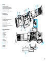 4
4
-
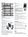 5
5
-
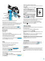 6
6
-
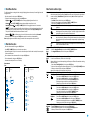 7
7
-
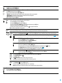 8
8
-
 9
9
-
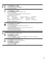 10
10
-
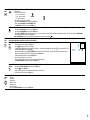 11
11
-
 12
12
-
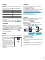 13
13
-
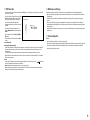 14
14
-
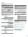 15
15
-
 16
16
-
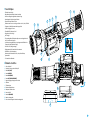 17
17
-
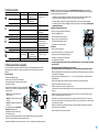 18
18
-
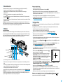 19
19
-
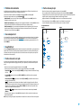 20
20
-
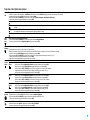 21
21
-
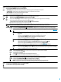 22
22
-
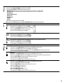 23
23
-
 24
24
-
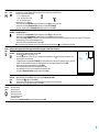 25
25
-
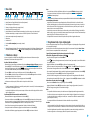 26
26
-
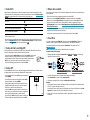 27
27
-
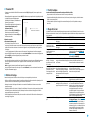 28
28
-
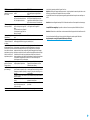 29
29
-
 30
30
-
 31
31
-
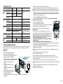 32
32
-
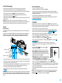 33
33
-
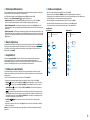 34
34
-
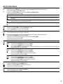 35
35
-
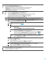 36
36
-
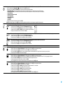 37
37
-
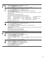 38
38
-
 39
39
-
 40
40
-
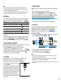 41
41
-
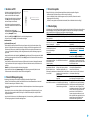 42
42
-
 43
43
-
 44
44
-
 45
45
-
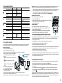 46
46
-
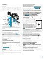 47
47
-
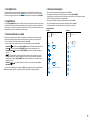 48
48
-
 49
49
-
 50
50
-
 51
51
-
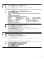 52
52
-
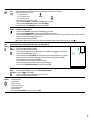 53
53
-
 54
54
-
 55
55
-
 56
56
-
 57
57
-
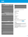 58
58
-
 59
59
-
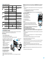 60
60
-
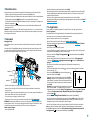 61
61
-
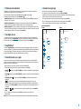 62
62
-
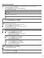 63
63
-
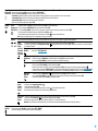 64
64
-
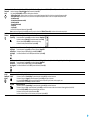 65
65
-
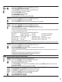 66
66
-
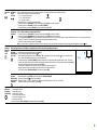 67
67
-
 68
68
-
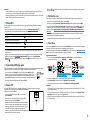 69
69
-
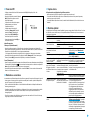 70
70
-
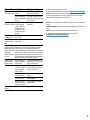 71
71
-
 72
72
-
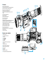 73
73
-
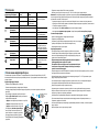 74
74
-
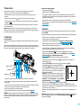 75
75
-
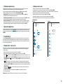 76
76
-
 77
77
-
 78
78
-
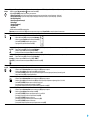 79
79
-
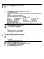 80
80
-
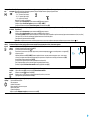 81
81
-
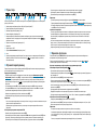 82
82
-
 83
83
-
 84
84
-
 85
85


Pulsar Trail 2 LRF Manuale del proprietario
- Tipo
- Manuale del proprietario
in altre lingue
Documenti correlati
-
Pulsar Trail Manuale del proprietario
-
-
-
Pulsar AXION 2 LRF XQ Guida utente
-
-
-
-
-
Pulsar XQ38 AXION LRF Thermal Imaging Scope Guida utente
-
Altri documenti
-
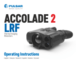 Pulsar Nightvision PULSAR Wärmebildgerät Binokular Accolade 2 LRF XP50 mit eingebautem Entfernungsmesser Manuale del proprietario
-
Yukon digital NV riflescopes Sentinel Manuale del proprietario
-
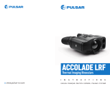 Pulsar Nightvision Wärmebildgerät Binokular Accolade LRF XP50 mit eingebauten Entfernungsmesser Manuale del proprietario
-
-
-
 Athlon 50-640 Guida utente
-
Zeiss Victory HT Istruzioni per l'uso
-
-


