2
Le informazioni contenute in questo documento sono state attentamente redatte e
controllate. Tuttavia non è assunta alcuna responsabilità per eventuali inesattezze.
Tutti i diritti sono riservati e questo documento non può essere copiato, fotocopiato,
riprodotto per intero o in parte senza previo consenso scritto della D.T.S .
D.T.S. si riserva il diritto di apportare senza preavviso cambiamenti e modifiche
estetiche , funzionali o di design a ciascun proprio prodotto. D.T.S non assume alcuna
responsabilità sull’uso o sull’applicazione dei prodotti o dei circuiti descritti.
The information contained in this publication has been carefully prepared and
checked. However, no responsibility will be taken for any errors. All rights are
reserved and this document cannot be copied, photocopied or reproduced, in part or
completely, without prior written consent from D.T.S.
D.T.S. reserves the right to make any aesthetic, functional or design modifications to
any of its products without prior notice. D.T.S. assumes no responsibility for the use or
application of the products or circuits described herein.
Les informations contenues dans le présent manuel ont été rédigées et contrôlées
avec le plus grand soin. Nous déclinons toutefois toute responsabilité en cas
d'éventuelles inexactitudes. Tous droits réservés. Ce document ne peut être copié,
photocopié ou reproduit, dans sa totalité ou partiellement, sans le consentement
préalable de D.T.S.
D.T.S. se réserve le droit d'apporter toutes modifications et améliorations esthétiques,
fonctionnelles ou de design, sans préavis, à chacun de ses produits. D.T.S. décline
toute responsabilité sur l'utilisation ou sur l'application des produits ou des circuits
décrits.
Las informaciones contenidas en este documento han sido cuidadosamente
redactadas y controladas. Con todo, no se asume ninguna responsabilidad por
eventuales inexactitudes. Todos los derechos han sido reservados y este documento
no puede ser copiado, fotocopiado o reproducido, total o parcialmente, sin previa
autorización escrita de D.T.S.
D.T.S. se reserva el derecho a aportar sin previo aviso cambios y modificaciones de
carácter estético, funcional o de diseño a cada producto suyo. D.T.S. no se asume
responsabilidad de ningún tipo sobre la utilización o sobre la aplicación de los
productos o de los circuitos descritos.

3
INDEX:
1-SYMBOLS .................................................................................................................. 4
2-GENERAL WARNING ............................................................................................... 5
3-GENERAL WARRANTY CONDITIONS ..................................................................... 5
4-TECHNICAL FEATURES .......................................................................................... 5
5-ACCESSORIES ......................................................................................................... 7
6-IMPORTANT SAFETY INFORMATION ..................................................................... 8
6.1 Fire prevention...................................................................................................... 8
6.2 Prevention of electric shock .................................................................................. 8
6.3 Safety ................................................................................................................... 8
6.4 Level of protection against the penetration of solid and liquid objects .................. 8
6.5 Waste Electrical and Electronic Equipment directive ............................................ 8
7-VOLTAGE AND FREQUENCY .................................................................................. 9
8-INSTALLATION ......................................................................................................... 9
8.1 Safety cable .......................................................................................................... 9
8.2 Protection against liquids .................................................................................... 11
8.3 Movement ........................................................................................................... 11
8.4 Risk of fire .......................................................................................................... 11
8.5 Forced ventilation ............................................................................................... 11
8.6 Ambient temperature .......................................................................................... 11
9-MAINS CONNECTION ............................................................................................. 12
9.1 Protection ........................................................................................................... 12
10-DMX SIGNAL CONNECTION ................................................................................ 13
10.1 DMX addresses ................................................................................................ 14
10.2 Selecting the DMX address .............................................................................. 14
11-FIRMWARE UPDATING ........................................................................................ 14
12-DISPLAY FUNCTIONS .......................................................................................... 15
13-PERIODIC CLEANING .......................................................................................... 20
14-PERIODIC CONTROLS ......................................................................................... 20
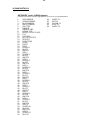
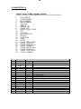
15-LEDs SEQUENCE FOR PIXEL TO PIXEL CONTROL ......................................... 21
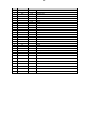
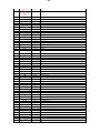
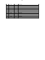
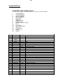
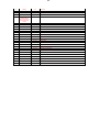
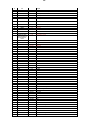
16-DMX PROTOCOL .................................................................................................. 22

4
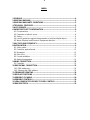
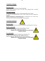
1- SYMBOLS
Graphic symbols used on this manual:
THIS SYMBOL INDICATES A HOT SURFACE
THIS SYMBOL INDICATES ELECTRIC
SHOCK RISK
THIS SYMBOL INDICATES GENERAL RISK
THIS SYMBOL MEANS “SUITABLE FOR
INDOOR USE ONLY”
THIS SYMBOL MEANS “SUITABLE FOR
MOUNTING ON NORMALLY FLAMMABLE
SURFACES”
THIS SYMBOL INDICATES THE MINIMUM
DISTANCE FROM THE ILLUMINATED OBJECTS
THIS SYMBOL MEANS “DO NOT STARE
AT THE OPERATING LIGHT SOURCE”
THIS SYMBOL INDICATES
PHOTOBIOLOGICAL SAFETY
THIS SYMBOL INDICATES THE EUROPEAN
COMMUNITY DIRECTIVE 2012/19/EC ON
WASTE ELECTRICAL AND ELECTRONIC
EQUIPMENT (WEEE)
!

5
2- GENERAL WARNING
Read the instruction contained in this user manual carefully, as they give important
information regarding safety during installation , use and maintenance.
The device is not for household use and must be installed by a qualified electrician or
experienced person.
Always disconnect the device from the mains before maintenance.
The device must always be equipped with an efficient ground connection.
3- GENERAL WARRANTY CONDITIONS
The unit is guaranteed for 36 months from the date of purchase against manufacturing
material defects.
4- TECHNICAL FEATURES
Overview
KATANA is the most advanced LED light ever designed for the entertainment market.
KATANA introduces a brand new type of light beam: the dynamic ‘blade’ projection.
Thanks to a custom 3.5° - 30° linear zoom, KATANA is capable to project an extra-
bright blade of light that cuts through any show.
Single pixel control lets you obtain stunning dynamic multicolor effects.
And a super-fast motorized tilt adds a dynamic impact to your lighting performance.
DTS Product code:
03.LDR016.F KATANA
LED Technology
* 12 x 20W OSTAR STAGE “N” FULL RGBW LEDs
* Pixel to pixel control
* 9600 Lumens
Optical group
* 3.5°(‘blade’ mode) - 30° linear motorized zoom
Colour generation
* 16 million colours
* Variable linear colour temperature (2700K – 8000K)
Tilt
* Motorized Tilt ±95°
* 16-bit movement resolution
Interface / Control / Programming
* Multi-function 4-Digit 7-Segment LED Display + 4 soft keys:
control / management / monitoring of the main parameters
* Controlled via DMX 512 and RDM standard digital communication protocols
* Internal operating system updatable via DTS RED BOX interface via “DTS firmware
upgrade utility” program on windows based PC

6
DMX
24 DMX channels (default), 64 DMX channels or 16 DMX channels
Power supply
* Electronic full-range 100-240Vac 50-60 Hz
* Power consumption: 300W Max
Connectors
* DMX: XLR 5 pins In / Out panel connectors
* Power supply: PowerCon TRUE1 In / Out panel connectors
Operating ambient temperature
-10° / 40°
Weight
16 Kg (product without brackets for ground installation)
International certifications
Certification CE
LED Class: Class 2 LED product

7
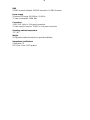
Dimensions
Packaging Dimensions (LxWxH)
1160 x 250 x 365 mm
Weight: 24 Kg
5- ACCESSORIES
As standard
• 1 x PowerCon TRUE1 female cable connector (cod. 0520P066)
• 1 x PowerCon TRUE1 male cable connector (cod. 0520P067)
• 1 x XLR 5 pins female cable connector (cod. 0508B147)
• 1 x XLR 5 pins male cable connector (cod. 0508B148)
• 2 x Omega bracket with “Fast Lock” connection 1/4 turn (cod. 02K00467)
• 2 x Bracket for ground installation with handles and rubber feet (already mounted on
the unit) (cod. 02SK0296)
• User’s manual
Optional (on request)
• “C” Clamp G60 black (max. load 50Kg) (cod. 0521A004)
• Aliscaf clamp for tube diameter 50 mm (max. load. 100Kg) (cod. 0521A008)
• Safety wire (3mm x 60 cm), max. capacity load 60Kg (cod. 0521A010)

8
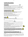
6- IMPORTANT SAFETY INFORMATION
6.1 Fire prevention:
-It is permissible to place the unit on normally flammable surfaces.
Suitable for mounting on normally flammable materials surfaces greater than 200°C
with some combustion time lag.
-Minimum distance from the closest illuminable surface: 0,5 m.
-Replace any blown or damaged fuses only with those of identical value (T 5A 250V).
Refer to the wiring diagram if there is any doubt.
-Connect the unit to mains power via a thermal magnetic circuit breaker.
6.2 Prevention of electric shock:
-High voltage is present inside the unit. Unplug the unit prior to performing any
function which involves touching the inside of the LED bar.
-The level of technology inherent in the KATANA requires the assistance of
specialised personnel for all servicing.
Please refer to an authorised DTS service centre.
-A good earth connection is essential for proper functioning of the unit.
-Never connect the unit without proper earth connection.
-The fixture should be located in places with a good air ventilation.
6.3 Safety:
-Risk Group 2 product according to EN 62471.
CAUTION. Do not look directly into the light output. May be harmful to the eyes and
skin.
-Do not stare at the operating light source.
-The unit is not for household use and must be installed by a qualified electrician or
experienced person.
-The LED bar should always be installed with bolts, clamps and other tools that are
capable of supporting the weight of the unit.
-Always use a second safety cable to sustain the weight of the unit in case of the
failure of the main fixing point.
-The external surface of the unit, at various points, may exceed 50°C. Never handle
the unit until at least 5 minutes have elapsed since the LED bar was turned off.
-Never install the fixture in an enclosed area lacking sufficient air flow.
The ambient temperature should not exceed 40°C.
6.4 Level of protection against the penetration of solid and liquid objects:
-The projector is classified as an ordinary appliance and its protection level against the
penetration of solid and liquid objects is IP 20.
6.5 Waste Electrical and Electronic equipment (WEEE) directive:
-The machine, accessories and packaging should be sorted for environmetal-friendly
Recycling.
For EC countries: according to the European Directive 2012/19/EC for Waste
Electrical and Electronic Equipment and its implementation into national right,
luminaires that are no longer usable must be collected separately and disposed of in
an environmentally correct manner.
!
!

9
7- VOLTAGE AND FREQUENCY
KATANA operates at 100-240Vac 50-60 Hz.
8- INSTALLATION
The unit is suitable for dry locations only.
KATANA may be either floor or ceiling mounted.
For floor mounting installations, KATANA is supplied with 2 brackets on the base with
rubber mounting feet.
For ceiling mounted installations, we recommend the use of appropriate clamps to fix
the unit to the mounting surface.
The supporting structure from which the unit is hung should be capable of bearing the
weight of the unit, as should any clamps used to hung it.
Four 1/4 turn Fast Locks connections placed in the base of the unit allow to hang the
KATANA by using the two Omega brackets (provided in the box) in conjuction with
fixing clamps for truss (clamps are not included into the unit box).
The Omega brackets can be installed on the unit even without remove the brackets
for ground installation fixed on the base of the unit.
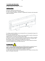
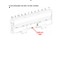
8.1- Safety cable
A safety cable must be securely fixed to the KATANA and to the suspension truss in
order to avoid the fixture accidentally falling should the main fixing point fail.
Make sure that the safety cable can bear the weight of the entire unit.
A suitable safety cable (code 0521A010) is available on demand.
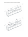
You may attach the safety cable to the attachment point (A) located on the base of the
fixture, as showed in the picture.
!

10
1) PRODUCT CEILING MOUNTED WITHOUT BRACKETS FOR GROUND INSTALLATION ON BOARD
2) PRODUCT CEILING MOUNTED WITH BRACKETS FOR GROUND INSTALLATION ON BOARD

11
8.2 Protection against liquids
The projector contains electric and electronic components which should under no
circumstances come into contact with oil, water or any other liquid.
The proper unit functioning would be compromised should this occur.
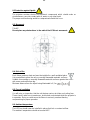
8.3- Movement
Tilt ±95°.
Do not place any obstructions in the path of the LED bar's movement.
8.4- Risk of fire
Each fixture produces heat and must be installed in a well-ventilated place.
It is permissible to place the unit on normally flammable materials surfaces.
Suitable for mounting on normally flammable materials surfaces greater than 200°C
with some combustion time lag.
Minimum distance from the object being illuminated is 0,5 m.
8.5- Forced ventilation
You will note, on inspection, that the unit features various air inlets and cooling fans.
These should, under no circumstances, be blocked or obstructed whilst the projector is
in operation. Doing so could cause the fixture to seriously overheat thereby
compromising its proper operation.
8.6- Ambient temperature
The LED bar should never be installed in places that lack a constant air flow.
The ambient temperature should not exceed 40°C.
!
!

12
9- MAINS CONNECTION
KATANA operates at 100-240Vac 50-60 Hz.
Prior to connecting the unit to your mains supply, ensure that the model in your
possession correctly matches the mains supply available.
For connection purposes, ensure that your plug is capable of supporting 2 amps
at 230Vac, or 4 amps at 90Vac.
Strict adherence to regulatory norms is strongly recommended.
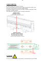
MAINS AC INPUT
100-240Vac 50-60 Hz
(PowerCon TRUE1 male panel connector)
MAINS AC OUTPUT
100-240Vac 50-60 Hz (16A Max)
Max 10 KATANA units @ 230Vac
Max 5 KATANA units @ 120Vac
(PowerCon TRUE1 female panel connector)
9.1- Protection
The use of a thermal magnetic circuit breaker is recommended for each KATANA.
!
FUSE
T 5A 250V

13
10- DMX SIGNAL CONNECTION
KATANA operates using the digital DMX 512 (1990) signal.
Connection between the mixer and the LED bar or between LED bars must be carried
out using a two pair screened ø 0.5 mm cable and a XLR 5 pins connector.
Ensure that the conductors do not touch each other.
Do not connect the cable ground to the XLR chassy.
The plug housing must be isolated. Connect the mixer signal to the DMX IN projector
plug and connect it to the next projector by connecting the DMX OUT plug on the first
projector to the DMX IN plug of the second one.
This way, all the projectors are cascade connected.
NB. If the display showing the DMX address flashes, then one of the following errors
has occurred:
- DMX signal not present
- DMX address not valid
- DMX reception problem
For Installations where long distance DMX cable connections are needed, we suggest
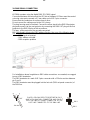
to use a DMX terminator.
The DMX terminator is a male XLR 5 pins connector with a 120 ohm resistor between
pin 2 and 3.
The DMX terminator must be plugged into the last unit (DMX out panel connector) of
the DMX line.
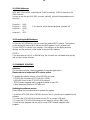
PLACE A 120 OHM RESISTOR BETWEEN PIN 2
AND 3 OF A MALE XRL CONNECTOR AND PLUG IT
INTO THE DMX OUT PANEL CONNECTOR OF THE
LAST UNIT CONNECTED TO THE DMX LINE
1
2
3
5
4
OUT
120 ohm
PIN 3
PIN 2

14
10.1-DMX Addresses
NICK NRG 1401 can be controlled with 24 DMX channels, 16 DMX channels or 64
DMX channels.
In order to use the unit in 24 DMX channels (default), set the following addresses on
the mixer:
Projector 1 A001
Projector 2 A025 If you want to select the next projector, just add “24”
Projector 3 A049
….. A….
projector 6 A121
10.2-Selecting the DMX address
1) Press the UP-DOWN key until you reach the required DMX channel. The numbers
on the display will start to flash (but the new DMX address hasn't yet been set).
2) Press ENTER to confirm your selection. The numbers on the display will stop
flashing and the projector is now setted to the new DMX address.
TRICKS:
If you keep pushed the UP or DOWN keys, the channels are calculated more quickly
and you get a faster selection.
11- FIRMWARE UPDATING
Attention:
This procedure require a base knowledge of computer applications.
Please refer to an authorised DTS service centre.
To update the software version of the KATANA you need:
- DTS RED BOX interface (DTS Code: 03.LA.008);
- USB-DMX Driver for the DTS RED BOX interface;
- “DTS Firmware upgrade utility” program installed on your PC;
- Latest firmware available for KATANA unit.
Updating the software version.
Please follow the procedure below to perform the update:
1. Install the DTS RED BOX USB-DMX driver on the PC you will use to update the unit
software.
2. Connect the DTS RED BOX interface to the PC by using a USB cable.
3. Connect the DTS RED BOX interface to the fixture by using a DMX cable.
4. Load the new firmware into the unit by using “DTS Firmware upgrade utility”
program.

15
Up-DownMENU ENTERUp-Down
Up-DownMENU ENTERUp-Down
Up-Down
Up-DownENTER
Up-DownENTER
ENTER
ENTER
ENTER
ENTER
Up-DownENTER
ENTER
ENTER
ENTER
Up-Down
Up-DownENTER
ENTER
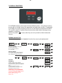
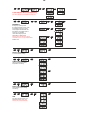
12- DISPLAY FUNCTIONS
The KATANA’s display panel shows all the available functions . Using these functions,
it is possible to change some of the parameters and add some functions. Changing the
DTS setting can vary the functions of the unit so that it does not respond to the DMX
512 used to control it. Carefully follow the instructions below before carrying out any
variations or selections.
NOTE: the symbol shows which key has to be pushed to obtain the desired
function.
Software version 2.04
(Menus and menu functions highlighted in red colour are not yet implemented)
DISPLAY POSITION:
Reverses display's reading depending
on the mounting position:
AA = On the ground (default)
VV = Suspended
DISPLAY STAND-BY:
To turn off the display or leave it always on.
OFF = Displat stand-by disabled (default)
ON = Display goes off after 30 seconds
DMX MODE
PERSONALITY
CHASE: 24 DMX channels (default).
This mode allows to combine pixel chase on a
foreground level with pixels on a background
level.
EXTENDED: 64 DMX channels.
This menu allows to control pixel to pixel.
STANDARD: 16 DMX channels.
DIMMER DELAY (Not yet implemented)
This menu allows to select the delay time (in
seconds) for the MASTER DIMMER channel
reaction to DMX Dimming command.
Range = OFF / 0.1 - 2.0 sec.
Default = OFF

16
MENU
Up-Down ENTER
Up-Down
Up-Down
Up-Down
Up-Down
ENTER
ENTER
ENTER
ENTER
ENTER
Up-Down
Up-Down
Up-Down
Up-Down
Up-Down
Up-Down
ENTER
ENTER
ENTER
ENTER
ENTER
ENTER
ENTER
Up-Down
ENTER Up-Down
ENTER
Up-Down
ENTER Up-Down
ENTER
Up-Down
ENTER Up-Down
ENTER
Up-Down
ENTER Up-Down
ENTER
Up-Down
ENTER Up-Down
ENTER
Up-Down
ENTER Up-Down
ENTER
Up-Down
ENTER Up-Down
ENTER
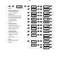
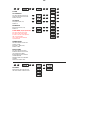
LED SET
RGBW MIN / MAX VALUES
This menu allows to select the
Minimum / Maximum levels for
Red, Green, Blue and White.
SMOOTH LEVEL
This menu allows to select the reaction
time (in milliseconds) for RED, GREEN,
BLUE, WHITE, and DIMMER channels
response to DMX Dimming command.
1 = Fast reaction time
20 = Slow reaction time
Range = OFF / 1 - 20 ms
Default = OFF
GAMMA CORRECTION
This menu allows to select
between Linear current output
or Quadratic current output for LEDs.
Linear = Linear current output.
Quadratic = Linear light output.
Default = Quadratic
OUTPUT FREQUENCY
This menu allows to adjust
the PWM frequency value (Hz)
in order to reduce flickering in
the process of your camera
recordings.
Range = 610 Hz – 20 KHz
Default = 610 Hz
BOOST
This menu allows to increase
the LED’s current from 70%
to 100%.
Default = ON

17
ENTER
ENTER
MENU Up-Down
Up-DownENTER ENTER
Up-Down
ENTER
ENTER
ENTER
Up-Down
ENTER
ENTER ENTER
Up-Down
Up-Down
Up-Down
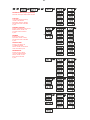
AUTOMATIC MODE (Not yet implemented)
Automatic demo game without DMX controller
STEP 01/16
Chase with 16 steps previously
created in REC MODE.
Speed time, Wait time, Dimmer,
Tilt and Zoom values selectable
by user.
PERSONAL COLOURS
Sixteen customizable Colour Macros.
RGBW, Dimmer, Shutter, Tilt
and Zoom values selectable
by user.
RAINBOW
Rainbow colours effect.
Speed time, Dimmer, Shutter,
Tilt and Zoom values selectable
by user.
FIXED COLOURS
Sixteen Colour Macros as
on “MACRO” channel.
Dimmer, Shutter, Tilt and Zoom
values selectable by user.
WHITE MACROS
Sixteen macros for White
color from 2700K to 8000K.
Dimmer, Shutter, Tilt and
Zoom values selectable
by user.

18
Up-DownMENU
Up-DownENTER
Up-DownENTER
ENTER
ENTER
ENTERENTER
Up-Down
MENU
Up-DownENTER
ENTER
MENU Up-Down
Up-Down
Up-Down
ENTER
ENTER
ENTER
Up-Down
ENTER
ENTER
ENTER
Up-Down
ENTER
ENTER
Up-Down
Up-Down
MENU
MENU
ENTER
ENTER
ENTER
Up-DownMENU
.
SLAVE MODE SETTING (Not yet implemented)
This menu allows to set KATANA as slave unit.
EMERGENCY
Emergency operating mode.
By setting Emergency mode, it will
be possible to select one of the
16 pre-programmed WHITE cues
that will then ran if DMX signal is
missing or not available.
Useful for Emergency EXIT
illumination on public areas.
Dimmer level, Tilt and Zoom values
selectable by user (not yet implemented).
Default = Off
DEFAULT SETTINGS
To restore default settings
TEMPERATURE
LEDs and LED Driver boards
temperature monitoring
SUPPLY VOLTAGE
Power supply’s output voltage
monitoring
TIME
This menu shows the total unit
life time and the RGBW LEDs
life time (not yet implemented).

19
Up-DownMENU ENTERUp-Down
Up-DownENTER
ENTER
ENTER
Up-Down
Up-DownENTER
ENTER
Up-Down
Up-DownENTER
ENTER
Up-Down
Up-DownENTER
ENTER
Up-Down
Up-DownENTER
ENTER
Up-Down
Up-DownENTER
ENTER
ENTER
ENTER
Up-DownMENU ENTERUp-Down
ENTER
ENTER
..
. .
SYSTEM
TILT INVERSION
This menu allows to set the Tilt
movement. Normal or Reversed.
Default = Normal.
TILT SPEED
Tilt Speed control (1-5)
Default = 5
ZOOM SPEED
Zoom speed control (1-5)
Default = 5
STUDIO MODE (Not yet implemented)
This menu allows to decrease
the speed of the zoom motors
to have a unit low noise operation.
ON = Silent operation
OFF = Zoom motor maximum
speed (default)
FAN MAX SPEED
This menu’ allows to select the
head fan speed.
50% (12V) - 100% (24V)
Default = 100%
RESET BY DMX
This menu allows to enable /
disable the Motors reset control
(Tilt and Zoom) via DMX.
Enabled: Motors reset enabled
via DMX (Default)
Disabled: Motors reset disabled
via DMX
Now: Instant motors reset.
SOFTWARE
Motors board (Tilt and Zoom) and
LED driver boards software version

20
13- PERIODIC CLEANING
Front lenses Glass
The dust can reduce the luminous output substantially.
Regularly clean the lenses using a soft cotton cloth, dampened with a specialist
glasses cleaning solution.
Fans and air passages
The fans and air passages must be cleaned approximately every 6 weeks.
This periodic cleaning will depend of course, on the conditions in which the projector is
operating.
Suitable instruments for performing this type of maintenance are a brush and a
common vacuum cleaner or an air compressor.
If necessary, clean the fans and air passages more frequently.
14- PERIODIC CONTROLS
Mechanical parts
Periodically check all mechanical parts and the gaskets, replacing them if necessary.
Electrical components
Check all electrical components for correct earthing and proper
attachment of all connectors, refastening if necessary.
Attention: Disconnect mains power prior to removing the
projector housing.
Fuse replacement
Locate the fuse, which protect the electronics, in the base of the
KATANA. Using a multimeter, test the condition of the fuse,
replacing it with one of equivalent type (T 5A 250V) if necessary.
Attention: Disconnect mains power prior to removing the
projector housing.
!
La pagina si sta caricando...
La pagina si sta caricando...
La pagina si sta caricando...
La pagina si sta caricando...
La pagina si sta caricando...
La pagina si sta caricando...
La pagina si sta caricando...
La pagina si sta caricando...
La pagina si sta caricando...
La pagina si sta caricando...
La pagina si sta caricando...
La pagina si sta caricando...
-
 1
1
-
 2
2
-
 3
3
-
 4
4
-
 5
5
-
 6
6
-
 7
7
-
 8
8
-
 9
9
-
 10
10
-
 11
11
-
 12
12
-
 13
13
-
 14
14
-
 15
15
-
 16
16
-
 17
17
-
 18
18
-
 19
19
-
 20
20
-
 21
21
-
 22
22
-
 23
23
-
 24
24
-
 25
25
-
 26
26
-
 27
27
-
 28
28
-
 29
29
-
 30
30
-
 31
31
-
 32
32