Nice POA1 Instructions And Warnings For The Fitter
- Tipo
- Instructions And Warnings For The Fitter

control units
POA1
istruzioni e avvertenze per l’installatore
Instructions and warnings for the fitter
Instructions et recommandations pour l’installation
Anweisungen und hinweise für den installateur
Instrucciones j advertencias para el instalador
Instrukcja dla instalatora

2
POA1
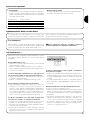
Warnings:
This manual has been especially written for use by quali-
fied fitters. The information provided in this manual is of no
use to end users!
This manual refers to the POA1 control unit and must not be
used for any other products.
The POA1 control unit has been designed to control electromechanical
actuators for automated swing gates or doors; any other use is consid-
ered improper and is consequently forbidden by the laws currently in
force. Do not install the unit before you have read all the instructions at
least once.
!
Table of contents: page
1 Product description 3
2 Installation 3
2.1 Typical system layout 3
2.2 Preliminary checks 4
2.3 Electrical connections 4
2.3.1 Electrical diagram 4
2.3.2 Description of the connections 5
2.3.3 Notes about connections 5
2.3.4 STOP type input 6
2.3.5 Examples of photocell connections without the 6
photo-test function
2.3.6 Examples of photocell connections with the 7
phototest function.
2.3.7 Checking the connections 8
2.4 Automatic search system for the limit switches 8
3 Testing 9
4 Diagnostics 9
5 Pre-set functions 9
page
6 Programmable functions 9
6.1 Direct programming 9
6.2 Level one programming, part one 10
6.3 Level one programming, part two 10
6.4 Level two functions 10
7 Programming 11
7.1 Programming methods 11
7.1.1 Level one programming: functions 12
7.1.2 Level two programming: parameters 12
7.2 Memory deletion 13
7.3 Example of level one programming 13
7.4 Example of level two programming 13
7.5 Programming diagram 14
8 Optional accessories 15
9 Servicing the POA1 control unit 15
9.1 Disposal 15
10 What to do if… 15
11 Technical characteristics 16
Annex Radio receiver 17

3
GB
The POA1 control unit operates on the basis of a current sensitivity
system which checks the load of the motors connected up to it. The
system automatically detects travel stops, memorises the running
time of each motor and recognises obstacles during normal move-
ment (anti-crush safety feature).
This feature makes installation easier as there is no need to adjust
the working times nor the leaf delay.
The control unit is pre-programmed for the normal functions, while
more specific functions can be chosen following a simple procedure.
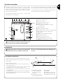
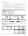
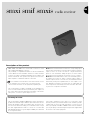
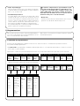
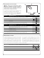
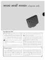
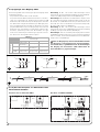
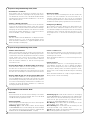
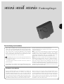
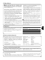
The most important components of the POA1 control unit have been
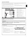
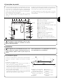
shown in Fig.1 in order to facilitate part identification.
12
D
C
A
FEGHILM
345 6 891011 12 13 14 15 167
B
P1
L1...L5
P2
P3
O
N
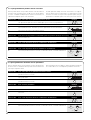
POA1 Control unit
A: 24V power supply connector
B: M1 motor connector
C: PS124 buffer battery connector
D: 500mA F type services fuse
E: Selector switch for delaying the opening of
motors M1 or M2
F: M2 motor terminal
G: Flashing light output terminal
H: Gate open indicator or electric lock output terminal
I: 24Vdc terminals for services and phototest
L: Input terminal
L1…L5: “Input” and “programming” LEDs
M: Terminal for radio aerial
N: “SM” radio receiver connector
O: Programming/diagnostics connector
P1, P2, P3: Programming buttons and leds
The control unit is housed inside special casing in order
to protect the electronic card from accidental damage.
!
1) Product description:
1
Automatic gate and door systems must only be installed
by qualified fitters in the full compliance with the law.
Be sure to note the warnings listed in the “Warnings for fit-
ters” file.
!
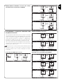
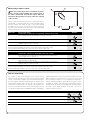
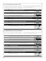
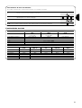
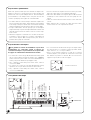
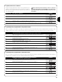
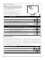
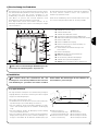
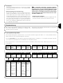
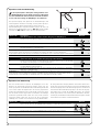
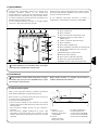
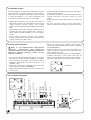
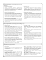
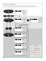
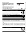
2.1) Typical system layout
The typical system layout has been illustrated below in order to
explain certain terms and aspects of an automatic 2-leaf swing door
or gate system.
In particular, please note that:
• Refer to the product instructions for the characteristics and con-
nection of the photocells.
• The “PHOTO” pair of photocells have no effect on the gate during
opening, while they reverse movement during closing.
• The “PHOTO1” pair of photocells stops both the opening and
closing manoeuvres.
• The “PHOTO2” pair of photocells (connected to the suitably pro-
grammed AUX input) have no effect during closing while they invert
movement during opening.
2) Installation
1. PP7024 Electromechanical
actuator (complete with
incorporated control unit
POA1) and
2. PP7224 Electromechanical
actuator without control unit
3. Flashing light
4. Key switch
5. “PHOTO” pair of photocells
6. “PHOTO1” pair of photocells
7. “PHOTO2” pair of photocells
1 2
3
4
5
7
PHOTO 1
PHOTO
PHOTO 2
6

4
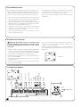
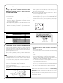
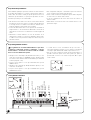
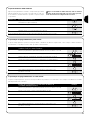
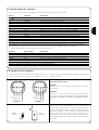
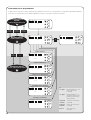
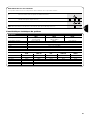
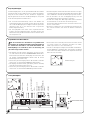
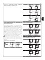
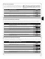
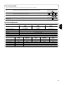
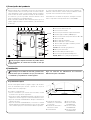
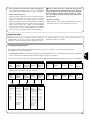
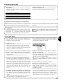
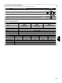
2.3.1) Electrical diagram
2.2) Preliminary checks
Before starting any kind of work, ensure that all the material is suit-
able for installation and complies with legal requirements. As well as
checking all the points listed in the “Warnings for fitters” file, this sec-
tion also contains a specific check list for the POA1 control unit.
• The “mechanical stops” must both be able to stop the gate from
moving and easily absorb all the kinetic energy accumulated dur-
ing movement (if necessary, use the stops for POP motors).
• The power supply line must be protected by magneto-thermal and
differential switches and equipped with a disconnection device.
There must be over 3mm between the contacts.
• Power the control unit using a 3 x 1.5mm
2
cable. Install an earth
plate near the control unit if the distance between the control unit
and the earth connection is over 30m.
• Use wires with a minimum cross section of 0.25mm
2
to connect
extra-low voltage safety circuits.
• Use shielded wire if the length is over 30m and only connect the
earth braid on the control unit side. The cross-section of the con-
nection cable for the motor must be at least 1.5mm
2
.
• Do not connect cables in buried boxes even if they are complete-
ly watertight.
2.3) Electrical connections
Unplug the unit from all sources of electricity in order
to ensure the fitter is protected and to prevent compo-
nents being damaged during electrical or radio receiver
connection.
•With the exception of the photocell inputs when the PHOTOTEST
function is activated, if the inputs of the NC (Normally Closed) con-
tacts are not in use they should be jumped with the “COMMON”
terminal. Refer to paragraph 2.3.6 for further information.
• If there is more than one NC contact on the same input, they must
be connected in SERIES.
• If the inputs of the NO (Normally Open) contacts are not used they
should be left free.
• If there is more than one NO contact on the same input, they must
be connected in PARALLEL.
•The contacts must be mechanical and potential-free. Stage con-
nections, such as those defined as "PNP", "NPN", "Open
Collector", etc. are not allowed.
• If the leafs overlap, use jumper E (Figure 1) to select which motor
starts up first during opening. M1 has an incorporated control unit,
M2 does not.
!
M2
Jumper “E”
M1
Flashing lamp 24vd.c.
+24Vd.c. PHOTOTEST
SCA/Electric lock
PHOTO1 (NC)
STEP-BY-STEP (NO)
+
-
+
-
AUX (NO)
0V
24Vd.c.
COMMON
PHOTO (NC)
STOP (NC)
POWER SUPPLY
L
N
AERIAL
11 12 13 14 15 161 2 3 4 5 6 7 8 9 10
M2
3
M2
M1
Jumper “E”

5
GB
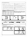
2.3.2) Description of connections
Here follows a brief description of the possible control unit output connections:
Terminals Function Description
L-N- Power supply line mains power supply
1÷3 Motor 2 * M2 motor connection
4÷5 Flashing light Connection of flashing light 24Vd.c. max. 25W
6÷7 Open Gate indicator/Elect.Lock Connection for Open Gate Indicator 24Vac max. 5W or Electric lock
12V max. 25VA please refer to the “Programming” chapter)
8 24Vdc/Phototest Power Supply +24V TX photocells for phototest (max. 100mA)
9 0Vdc 0V Power supply for services
10 24Vdc Power input for services, RX photocells, etc. (24Vac max. 200mA)
11 Common Common for all inputs (+24Vdc)
12 STOP **Input with STOP function (emergency, safety shutdown)
13 PHOTO NC Input for safety devices (photocells, sensitive edges)
14 PHOTO1 Input NC for safety devices (photocells, sensitive edges)
15 STEP-BY-STEP Input for cyclical functioning (OPEN-STOP-CLOSE-STOP)
16 AUX *** Auxiliary input
17÷18 Aerial Connection for the radio receiver aerial
* This is not used for single leaf gates (the control unit automatically recognises if only one motor has been installed).
** The STOP input can be used for “NC” or constant resistance 8,2kΩ contacts (please refer to the “Programming” chapter)
*** The auxiliary input AUX may be programmed in one of the following functions:
Function Input type Description
PARTIAL OPEN TYPE 1 NO Fully opens the upper leaf
PARTIAL OPEN TYPE 2 NO Opens the two leaf half way
OPEN NO Only carries out the opening manoeuvre
CLOSE NO Only carries out the closing manoeuvre
PHOTO 2 NC PHOTO 2 function
DISABLED - - No function
Unless otherwise programmed, the AUX input performs the Partial Open TYPE 1 function
Most connections are extremely simple and many of them are direct
connections to a single user point or contact.
The following figures show examples of how to connect external
devices.
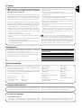
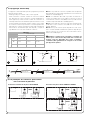
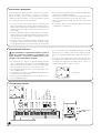
2.3.3) Notes about connections
Key switch connection
Example 1
How to connect the switch in order to perform the STEP-BY-STEP
and STOP functions.
Example 2
How to connect the switch in order to perform the STEP-BY-STEP
function and one of the auxiliary input functions (PARTIAL OPENING,
OPEN ONLY, CLOSE ONLY …).
Connection for Gate Open Indicator/Electric lock
If the gate open indicator has been programmed, the output can be
used as an open gate indicator light. It flashes slowly during open-
ing, and quickly during closing. If it is on but does not flash, this indi-
cates that the gate is open. If the light is off, the gate is closed. If the
electric lock has been programmed, the output can be used as an
electric lock. The electric lock will activate for 3 seconds each time
opening begins.
CNC NO C NO NC NONC C NCCNO
15
11
11
1612
11
15
11
STEP-BY-STEP STEP-BY-STEPSTOP AUX
6
6
24Vdc
max 5W
12Vac
max 25VA
7
7
Exemple 1 Exemple 2

6
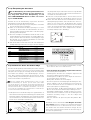
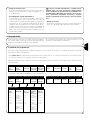
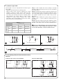
The POA1 control unit can be programmed for two types of STOP
input:
- NC type STOP for connecting up to NC type contacts
- Constant resistance STOP: it enables the user to connect up to the
control unit of devices with 8.2kΩ constant resistance (e.g. sensi-
tive edges). The input measures the value of the resistance and
disables the manoeuvre when the resistance is outside the nomi-
nal value. Devices with normally open “NO” or normally closed
“NC” contacts, or multiple devices, even of different types, can be
connected to the constant resistance STOP input, provided that
appropriate adjustments are made. For this purpose, refer to the
following the table:
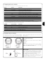
Note 1. Any number of NO devices can be connected to each oth-
er in parallel, with an 8.2KΩ termination resistance (Figure 4).
Note 2. The NO and NC combination can be obtained by placing
the two contacts in parallel, and placing an 8.2KΩ resistance in
series with the NC contact. It is, therefore, possible to combine 3
devices: NO, NC and 8.2KΩ).(Figure 5)
Note 3. Any number of NC devices can be connected in series to
each other and to an 8.2KΩ resistance (Figure 6).
Note 4. Only one device with an 8.2KΩ constant resistance output
can be connected; multiple devices must be connected “in cascade”
with a single 8.2KΩ termination resistance (Figure 7)
If the constant resistance STOP input is used to con-
nect devices with safety functions, only the devices with
8.2KΩ constant will resistance output guarantee the fail-
safe category 3.
!
2.3.4) STOP type input
Table 1
1st device type:
NO NC 8,2KΩ
o 2nd device type:
NO
NC
8,2KΩ
In parallel
(note 1)
(note 2) In parallel
(note 1)
In series
(note 3)
In series
In parallel In series (note 4)
NA
NA
11
12
8,2KΩ
NA
NC
11
12
8,2KΩ
11
12
8,2KΩ
NC
NC
11
12
Sensitive edge
1
Sensitive edge
2
Sensitive edge
n
8,2KΩ
4
7
5 6
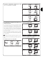
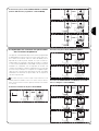
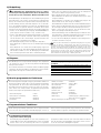
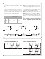
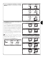
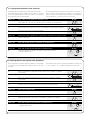
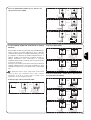
2.3.5) Examples of photocell connections without
the phototest function.
Connecting the PHOTO photocell only. PHOTO and PHOTO1 connections
14
11
10
9
13
11
10
9
1123452
FOTO
TX RX
9
10
10
9
13
11
11
14
10
10
9
9
TX
FOTO 1
RX
TX
FOTO
RX
1123452
1123452
PHOTO
PHOTO
PHOTO 1
NO NO
NO

7
GB
PHOTO, PHOTO1 and PHOTO2 connections (The auxiliary
input AUX must be programmed as PHOTO2)
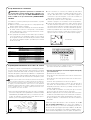
2.3.6) Examples of photocell connections with
the phototest function.
The programmable PHOTO-TEST function is a feature on the POA1
control unit (this function is not activated initially). This is an excellent
solution as regards the reliability of safety devices and places the
control unit and safety devices in “Category 2” of UNI EN 954-1
standard (ed. 12/1998). The safety devices are checked whenever a
manoeuvre is started, and will only begin if everything is in order.
This is only possible using a special configuration of the safety device
connections. The “TX” photocell transmitters are basically powered
separately from the “RX” receivers.
When the phototest is activated, the FOTO, FOTO1 and FOTO2 inputs will
be subjected to testing. If one of these inputs is not being used, it must be
connected to terminal n°8. Please consult the following figures for examples
of connections.
Connecting the PHOTO photocell only.
PHOTO and PHOTO1 connections
PHOTO, PHOTO1 and PHOTO2 connections (The auxiliary
input AUX must be programmed like PHOTO2)
13
9
11
10
10
11
14
9
10
9
9
10
11
16
10
9
9
10
TX
TX
RX
FOTO 2
FOTO 1
RX
TX
FOTO
RX
1123452
1123452
1123452
14
8
9
8
9
13
11
10
RXTX
1123452
FOTO
9
8
14
11
9
10
9
8
9
11
13
10
TX
FOTO 1
RX
TX
FOTO
RX
1123452
1123452
9
8
16
11
9
8
9
10
14
11
9
9
8
9
10
13
11
10
TX
FOTO 2
RX
TX
FOTO 1
RX
TX
FOTO
RX
1123452
1123452
1123452
PHOTO
PHOTO
PHOTO
PHOTO 1
PHOTO 1
PHOTO 2
PHOTO 1
PHOTO 2
PHOTO

8
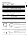
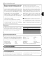
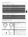
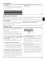
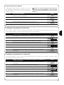
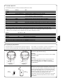
2.3.7) Checking the connections
WARNING: The next operations involve work being car-
ried out on live circuits. Some parts have mains voltage
running through them and are therefore EXTREMELY DAN-
GEROUS! Pay maximum attention to what you are doing
and NEVER WORK ALONE!
The system can be checked once the connections for the automa-
tion have been made.
1. Power the control unit and check that all the LEDs flash rapidly for
a few seconds.
2. Check that there is a voltage of approximately 32Vdc on terminals
9-10. If not, unplug the unit immediately and carefully check the
connections and input voltage.
3. After initially flashing rapidly, the P1 LED will indicate the control
unit is working correctly by flashing regularly at 1 second intervals.
When there is a variation in the inputs, the “P1” led will rapidly flash
twice to show that the input has been recognised.
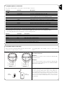
4. If the connections are correct, the LED for the “NC”-type inputs
will be on, while those for the “NO” type inputs must be off. Here
follows Figure 8 illustrating the LEDs on, and the summary table of
the various possible situations:
5. Check that the relative LEDs switch on and off when the devices
connected to the inputs are operated.
6. Check that by pressing P2 both motors perform a short opening
manoeuvre, and the motor of the upper leaf starts first. Block the
manoeuvre by pressing P2 again. If the motors do not start up for
opening, invert the polarities of the motor cables. If, however, the
first one to move is not the upper leaf, operate jumper E (see fig-
ure).
!
INPUT INPUT TYPE STATUS LED
STOP STOP NC L1 On
CONSTANT RESISTANCE L1 On
STOP 8,2KΩ
PHOTO L2 On
PHOTO 1 L3 On
STEP-BY-STEP L4 Off
AUX OPEN PARTIALLY type 1 L5 Off
OPEN PARTIALLY type 2 L5 Off
OPEN ONLY L5 Off
CLOSE ONLY L5 Off
PHOTO2 L5 On
2.4) Automatic search system for the limit switches
On the successful completion of the various controls, start the auto-
matic search system phase for the limit switches. This work is nec-
essary as the POA1 control unit must “measure” how long the open-
ing and closing manoeuvres take.
This procedure is completely automatic and detects the mechanical
opening and closing stops by measuring the load on the motors.
If this procedure has already been carried out, in order to reactivate it, the
user must first delete the memory (see the “Memory deletion” chapter). In order
to check whether the memory contains any limit switch parameters, turn the
power supply to the control unit on and then off again. If all the LEDs flash rapid-
ly for approximately 6 seconds, the memory is empty. If, however, they only flash
for 3 seconds, the memory already contains some limit switch parameters.
• Before starting limit switch searching, make sure that all the safety
devices are enabled (STOP, PHOTO and PHOTO1).
The procedure will be immediately interrupted if a safety device trig-
gers or a command arrives.
• Ideally the doors should be half open, although they can be in any
position.
•Press the P2 button to begin searching, which runs as
follows:
- Both motors open briefly
- Motor closes the lower leaf until it reaches the mechanical closing
stop.
- The upper leaf motor closes until it reaches the mechanical clos-
ing stop.
- The motor of the upper leaf begins to open.
- After the programmed delay, opening of the lower leaf begins.
If the delay is insufficient, block the search by pressing P1, then
modify the time (see the “Programming” chapter).
- The control unit measures the movement required for the motors
to reach the opening mechanical stops.
-Complete closing manoeuvre. The motors can start at different
times, the aim is to prevent the leafs from shearing by maintaining
a suitable delay.
- End of the procedure with memorisation of all measurements.
All these phases must take place one after the other without any
interference from the operator. If the procedure does not continue
correctly, it must be interrupted with the P1 button.
Repeat the procedure, modifying some parameters if necessary, for
example the current sensitivity cut-in thresholds (see the
“Programming” chapter).
8
9
M2
M1
Jumper “E”

9
GB
The automation system must be tested by qualified and
expert staff who must establish which tests to perform
depending on the relative risk.
Testing is the most important part of the whole installation phase. Each
single component, e.g. motors, radio receiver, emergency stop, photo-
cells and other safety devices, may require a specific test phase; please
follow the procedures shown in the respective instructions manuals.
Carry out the following procedure in order to test the POA1 control unit,
(the sequence refers to the POA1 control unit with pre-set functions).
• Make sure that the activation of the STEP-BY-STEP input generates
the following sequence of movements: Open, Stop, Close, Stop.
• Make sure that the activation of the AUX input (Type 1 partial open-
ing function) manages the Open, Stop, Close, Stop sequence of
the motor of the upper leaf only, while the motor of the lower leaf
remains in the closed position.
• Perform an opening manoeuvre and check that:
- the gate continues the opening manoeuvre when PHOTO is
engaged.
- the opening manoeuvre stops when PHOTO1 is engaged and only
continues when PHOTO1 is disengaged.
- The manoeuvre stops when PHOTO2 (if installed) is engaged and
the closing manoeuvre starts.
•Make sure that the motor switches off when the door reaches the
mechanical stop.
• Perform a closing manoeuvre and check that:
- The manoeuvre stops when PHOTO is engaged and the opening
manoeuvre starts.
- The manoeuvre stops when PHOTO1 is engaged and the opening
manoeuvre starts when PHOTO1 is disengaged.
-
The gate continues the closing manoeuvre when PHOTO2 is engaged.
• Check that the stopping devices connected to the STOP input
immediately stop all movement.
• Check that the level of the obstacle detection system is suitable for
the application.
- During both the opening and the closing manoeuvres, prevent the
leaf from moving by placing an obstacle and check that the
manoeuvre inverts before exceeding the force set down by law.
• Other checks may be required depending on which devices are
connected to the inputs.
If an obstacle is detected as moving in the same direction for 2 consecu-
tive manoeuvres in the same direction, the control unit partially inverts both
motors for just 1 second. At the following command, the leafs begin the open-
ing manoeuvre and the first current sensitivity cut-in for each motor is consid-
ered as a stop during the opening cycle. The same happens when the mains
power supply is switched on: the first command is always an opening manoeu-
vre and the first obstacle is always considered as an open limit switch.
!
3) Testing
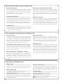
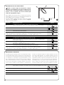
The diagnostics LED P2 indicates any problems or malfunctions
revealed by the control unit during the manoeuvre.
A sequence with a certain number of flashes indicates the type of
problem and remains active until the following manoeuvre begins.
The table below summarises this information:
Number Type of malfunction
Flashing P2 LED
1 M1 current sensitivity device triggering
2 M2 current sensitivity device triggering
3 STOP input cut-in during the manoeuvre.
4 Phototest error
5
Output overcurrent gate open indicator or electric lock
4) Diagnostics
The POA1 control unit features some programmable functions. After
the search phase these are pre-set in a typical configuration which
satisfies most automatic systems.
These functions can be changed at any time, both before and after
searching, by carrying out the relevant programming procedure (refer
to the “Programmable functions” chapter).
• Motor movement: : fast
• Automatic closing : active
• Condominium function : deactivated
•Pre-flashing : deactivated
• Close after photo : deactivated
• Opening delay : level 2 (10%)
• Phototest : deactivated
• Gate open indicator/Electric Lock : Gate open indicator
• STOP input : NC type
• Heavy gates : deactivated
•Proportional gate open indicator : deactivated
• Pause time : 20 seconds
• Auxiliary input : type 1 partial opening (only
the upper leaf motor is activated)
• Current sensitivity : Level 2
5) Pre-set functions
To ensure the system is best suited to the user’s requirements, and
safe in the various different conditions of use, the POA1 control unit
offers the possibility to programme several functions or parameters,
as well as the function of a number of inputs and outputs.
6) Programmable functions
6.1) Direct programming
• Slow/rapid movement
The user can choose the speed of movement of the gate, at any
time (with the motor arrested) simply by operating the P3 key at any
time the control unit is not being programmed. If LED L3 is off, this
shows that the slow movement has been set, if on the fast one has.

10
6.2) Level one programming, part one
• Automatic closing:
This function features an automatic closing cycle after the pro-
grammed pause time; the pause time is factory set to 20 seconds
but it can be modified to 5, 10, 20, 40 or 80 seconds.
If the function is not activated, the system will run “semi-automat-
ically”.
• “Condominium” function:
This function is useful when the automatic system is radio-com-
manded by many different people. If this function is active, each
command received triggers an opening manoeuvre that cannot be
interrupted by further commands. If the function has been deacti-
vated, a command causes: OPEN-STOP-CLOSE-STOP
•Pre-flashing:
This function activates the flashing light before the manoeuvre
begins for a time that can be programmed to 2, 4, 6, 8 or 10 sec-
onds. If the function is deactivated, the light will start flashing when
the manoeuvre starts.
• Close after photo:
During the automatic closing cycle, this function reduces the
pause time to 4 seconds after the PHOTO photocell has disen-
gaged, i.e. the gate closes 4 seconds after the user has passed
through it. If the function is deactivated, the whole programmed
pause time will pass.
• Opening delay
During opening, this function causes a delay in the activation of the
lower leaf motor compared with the upper one This is necessary in
order to prevent the leafs from getting stuck. There is always a
standard delay during closing, calculated automatically by the con-
trol unit in order to ensure the same delay as the one programmed
for opening.
• Phototest function
The POA1 control unit can also activate the phototest procedure.
The correct functioning of the photocells is checked every time a
manoeuvre starts. In order to be able to use this function, the pho-
tocells must be correctly connected up (refer to paragraph 2.3.6)
and the function then activated. If the function is deactivated, the
control unit will not carry out the photo-test.
• Open gate indicator light / electric lock
If the function is activated, terminals 6-7 can be used to connect
up the electric lock. If the function is deactivated, terminals 6-7 can
be used to connect up a 24V gate open indicator.
• NC Type or Constant Resistance STOP Input
If the function is activated, the STOP input is set to “8.2KΩ
Constant Resistance”. In this case, there must be a 8.2KΩ +/-25%
resistance between the common and the input to enable the oper-
ation.
If the function is not set, the configuration of the STOP input will
enable it to function with NC type contacts.
• Light/heavy gates
If the function is activated, the control unit enables the user to
manage heavy gates, setting the acceleration ramps and slow-
down speeds during closing differently.
If the function is deactivated, the control unit will be set to manage
light gates.
•Proportional Open Gate Indicator
If the function is activated, the gate open indicator output will be
set with the proportional flashing light. This means that during
opening, the flashing becomes more intense as the leafs come
nearer to the opening stops; vice-versa, for closing, the flashing
becomes less intense as the leafs come nearer to the closing
stops.
If the function is deactivated, the light will flash slowly during open-
ing and rapidly during closing.
6.3) Level one programming, part two
6.4) Level two functions
• Pause time
The pause time, namely the time which lapses between opening
and closing during automatic functioning, can be programmed to
5, 10, 20, 40, and 80 seconds.
• Auxiliary Input AUX
The control unit offers an auxiliary input which can be set to carry
out one of the following 6 functions:
-
Partial opening type 1: this carries out the same function as the
STEP-BY-STEP input. It causes only the upper leaf to open. It only
works if the gate is closed completely, otherwise the command is inter-
preted as if it were a STEP-BY-STEP command.
- Partial opening type 2: this carries out the same function as the
STEP-BY-STEP input. It causes the two leafs to open for half the
time it would take them to open completely. It only functions if the
gate is closed completely, otherwise the command is interpreted
as if it were a STEP-BY-STEP command.
- Open only: this input only causes opening in the Open- Stop-
Open-Stop sequence.
- Close only: this input only causes closing in the Close-Stop-
Close-Stop sequence.
- Photo 2: this carries out the function of the “PHOTO 2” safety
device.
- Disabled: the input will not carry out any function.

11
GB
•Pre-flashing time:
A manoeuvre warning sign can be activated on the flashing light
before each manoeuvre begins, and the time programmed to 1, 2,
4, 6, 8 and 10 seconds.
• Current sensitivity:
The control unit is equipped with a system which measures the
current absorbed by the two motors used to detect the mechani-
cal stops and any obstacles when the gate is moving. Since the
current absorbed depends on a number of conditions, including
the weight of the gate, friction, wind and variations in voltage, the
cut-in threshold can be changed.
There are 6 levels: 1 is the most sensitive (minimum force), 6 is the
least sensitive (maximum force).
If the “current sensitivity” function (together with oth-
er vital features) is adjusted correctly, the system will
comply with European standards, EN 12453 and EN
12445, which require techniques or devices to be used to
limit force and danger during the functioning of automat-
ic gates and doors are moved.
• Leaf delay:
The delay in starting up the motor of the lower leaf can be pro-
grammed to 5, 10, 20, 30 or 40% of the working time.
!
7.1) Programming methods
The P1, P2 and P3 buttons are used for all the programming phases, while the 5 Leds (L1, L2…L5) indicate the selected “parameter”.
There are two different programming levels:
• At level 1, the functions can be activated or deactivated. Each Led (L1, L2…L5) corresponds to a function: if the Led is on, the function is
active; if it is off, it is deactivated.
Level one consists in 2 parts which can be selected using the P3 button. The corresponding LED P3 indicates which of the 2 parts has been
selected.
• It is possible to pass to the second level from level one of part one. At this second level the user can choose the parameter relating to the
function. A different value corresponds to each LED which must be associated to the parameter.
Led L1 Led L2 Led L3 Led L4 Led L5
Automatic “Condominium” Pre-flashing Close
Opening delay
closing function after photo
All the functions described in the “Programmable functions” chapter
can be selected by means of a programming phase which terminates
by memorising the choices made.
The control unit therefore has a memory which stores the functions
and parameters relative to the automation process.
7) Programming
Level one (fixed LED P1): part one - (LED P3 off)
Led L1 Led L2 Led L3 Led L4 Led L5
Phototest Electric Lock Resistive STOP Heavy gates Proportional
Open Gate
Level one (fixed LED P1): part two - (LED P3 on)
Led L1 Led L2 Led L3 Led L4 Led L5
Automatic “Condominium” Pre-flashing Close
Opening delay
closing function after photo
Level one (fixed LED P1): part one - (LED P3 off)
Led L1 Led L2 Led L3 Led L4 Led L5
Phototest Electric Lock Resistive STOP Heavy gates Proportional
Open Gate
Level one (fixed LED P1): part two - (LED P3 on)
Second level:
Parameter: Parameter: Parameter: Parameter: Parameter:
Pause Time AUX Input Pre-flashing Current Leaf Delay
Time sensitivity
L1: 5s L1: Open L1: 2s L1: Level 1 L1: 5%
partially type 1 (most sensitive)
L2: 10s L2: Open L2: 4s L2: Level 2 L2: 10%
partially type 2
L3: 20s L3: Open only L3: 6s L3: Level 3 L3: 20%
L4: 40s L4: Close only L4: 8s L4: Level 4 L4: 30%
L5: 80s L5: Photo 2 L5: 10s L5: Level 5 L5: 40%
(least sensitive)
All LEDs off: All LEDs off:
input not used level 6
(max. current
sensitivity)

12
3s
7.1.1) Level one programming: functions
At level one, the functions can be activated or deactivated.
At level one, LED P1 is always on; if LEDs L1, L2…L5 are on, the
functions are activated; if the LEDs are off, the functions are deacti-
vated. A flashing LED indicates which function has been selected;
short flashes indicate the function has been deactivated; long flash-
es indicate the function has been activated. Press P3 to pass from
part one programming to part two programming, and vice-versa.
3s
Table “A1” Entering level one programming: Example
1. Press and hold down buttons P1 and P2 for at least 3 seconds
The programming mode has been entered if all the Leds start flashing quickly
1. Press P1 repeatedly until the flashing Led reaches the function required.
2. Press P2 to activate or deactivate the function.
Table “A3” To pass from part one to part two of level one (and vice-versa): Example
1. Press P3. button
Table “A4” To exit level one and save the modifications: Example
1. Press and hold down buttons P1 and P2 for at least 3 seconds
P1 P2
P3
P1
P2
Table “A2” Activating or deactivating a function: Example
P1 P2
3s or 60s,
or
Table “A5” Exiting level one and delete the modifications: Example
1. Either press P1 for at least 3 seconds, or wait for 1 minute, or disconnect the power supply
P1
3s
7.1.2) Level two programming: parameters
The function parameter can be chosen at level two. Level two can
only be reached from level one.
At level 2 the P1 Led flashes quickly while the 5 Leds (L1, L2…L5)
indicate the selected parameter.
3s
Table “B1” Entering level two programming: Example
1. Enter level one programming by pressing P1 and P2 for at least 3 seconds
1. Press P2 repeatedly until the Led reaches the desired parameter
Table “B3” Returning to level one: Example
1. Press P1
Table “B4” Exiting level one and saving modifications: Example
1. Press and hold down buttons P1 and P2 for at least 3 seconds
P1 P2
P1
P2
Table “B2” Selecting the parameter: Example
P1 P2
2. Select the function by pressing P1 until the flashing Led reaches the point required.
3s or 60s,
or
Table “B5” Exiting level one and cancelling modifications: Example
1. Either press P1 for at least 3 seconds, or wait for 1 minute, or disconnect the power supply
P1
P1
3s
3. Enter level two by pressing the P2 button for at least 3 seconds
P2

13
GB
7.2) Memory deletion
Each new programme replaces the previous settings. It is usually
unnecessary to “delete all” the memory. If required, the memory can
be totally deleted by performing this simple operation:
As all the functions return to their pre-set values after
the memory is deleted, a new search for the mechanical
stops must be carried out.
!
Table “C1” Delete memory: Example
Example of level one programming: activate the “Condominium” function and Example
“Electric lock” output
1. Switch the power supply to the control box off, and wait until all the LEDs have gone off
(remove fuse F1 if necessary).
2. Press P1 and P2 on the board down and keep them pressed down.
P1 P2
3. Switch the power supply on again.
3s
4. Wait at least 3 seconds before releasing the two keys
If the memory was deleted correctly, all the Leds will switch off for 1 second.
P1 P2
7.3) Example of level one programming
The following examples show how to activate or deactivate a level one function, the “Condominium” function, for example, and prepare the
“Gate Open Indicator” output in order to activate the electric lock.
3s
1. Access the level one programming mode by pressing P1 and P2, and keeping them pressed
down for at least 3 seconds.
P1 P2
x1
2. Press P1 once to move the flashing Led to the Led 2 (the flashes will be short)
2
P1
3. Activate the “Condominium” function by pressing P2 (the flashes will be longer).
P2
4. Press P3 once in order to activate part two (the P3 LED will switch on)
P3
5. Press P1 once to move the flashing Led to the Led 2 (the flashes will be short)
6. Activate the “Electric lock” output by pressing P2 (the flashes will be longer).
P2
3s
7. Press P1 and P2 for at least 3 seconds to exit the programming mode and save modifications
P1 P2
2
P1
Example of level two programming: modifying “current sensitivity” Example
7.4) Example of level two programming
This example shows how to modify a level two parameter, for example, how to modify current sensitivity intil “level 5”.
3s
1. Access the level one programming mode by pressing P1 and P2 for at least 3 seconds
P1 P2
x3
2. Press P1 three times to move the flashing Led to the Led 4
4
P1
x3
5
P2
3s
3. Access level two by pressing P2 for at least 3 seconds.
P2
4. Press P2 three times until Led 5 switches on
5. Return to level one by pressing P1.
P1
3s
6. Press P1 and P2 for at least 3 seconds to exit the programming mode and save modifications
P1 P2

14
ALT Photo Photo
1
Step
by
step
AUX
Normal
operation
Led P1 Slow flashing
Level one
Led P1 On permanently
Level two
Led P1 Rapid flashing
type 1
p.o
type 2
p.o
only
opening
only
closing
Photo 2
All Leds off ➡ max. current sensitivity
P1+P2
for 3 secs
P1
for 3 secs
(NO SAVE)
P1+P2
for 3 secs
(SAVE)
Autom.
closing
Cond. Pre-
flashing
Close
after
Photo
Opening
delay
On
Off
On
Off
AUXILIARY INPUT (*)
PRE-FLASHING TIME
246
seconds
810
CURRENT SENSITIVITY
123
Level
45
OPENING DELAY
51020
%
30 40
51020
seconds
40 80
PAUSE TIME
P1
P2
for 3 secs
P1
P1
P2
P3
P1
P2
P3
P1
P2
P3
P1
P2
P3
P1
P2
P3
P1
P2
P3
P2
P3
Photo-
test
Electric
Lock
Resist.
STOP.
Heavy
gates
Proportional
Gate
Open
P3
P1
P2
P3
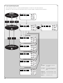
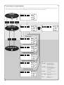
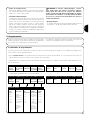
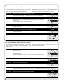
7.5) Programming diagram
The following figure shows the complete programming diagram of the functions and relative parameters.
This figure also shows the functions and parameters either as they were initially or following total memory deletion.
(*)
a.p. type 1 type 1 partial open, upper leaf
moves [N.O.]
a.p. type 2 type 2 partial opening, both motors
move for 1/2 the working time set
[N.O.]
Only open open
➔stop➔open➔stop… [N.O.]
Only closed close
➔stop➔close➔stop… [N.O.]
Photo 2 used as photo 2 [n.c.]

15
GB
• “RADIO” Card
The control unit has a connector for fitting a 4 channel radio card
complete with SM slot. This remote control device functions by
means of transmitters which act on the inputs as per the following
table:
Output Receiver Control unit input
N° 1 STEP-BY-STEP
N° 2 AUX (reset value: Partially Open 1)
N° 3 “Open only”
N° 4 “Only close”
• PS124 Buffer Battery
PS124 buffer batteries can be used to supply the control unit in
case of network blackouts.
8) Optional accessories
As the POA1 control unit is electronic it requires no particular mainte-
nance. However, at least every six months the efficiency of the entire
system must be checked according to the information described in
the “Testing” chapter.
9) POA1 control unit maintenance
This section will help fitters to solve some of the most common prob-
lems that may arise during installation.
No LEDs are on:
• Check whether the control unit is powered (measure a voltage of
about 32Vdc at terminals 9-10).
• Check the 2 fuses, if not even the P1 Led is on or flashing a seri-
ous fault has probably occurred and the control unit must there-
fore be replaced.
The P1 LED flashes regularly but the INPUT LED’s do not
reflect the state of the respective inputs.
• Switch the unit off for the moment in order to exit a possible pro-
gramming phase.
• Carefully check the connections on terminals 11 to 16.
The “Automatic search” procedure does not start up.
• The “Automatic search” procedure only starts if it has never been
performed before or if the memory has been deleted. To check
whether the memory is empty switch off the unit for a moment.
When it is switched on again, all the Leds should flash rapidly for
about 6 seconds. If they only flash for 3 seconds, the memory
already contains valid values. If a new “Automatic search” is
required, the memory must be completely deleted.
The “Automatic search” procedure has never been per-
formed but it either does not start or it behaves incorrectly
• The system and all the safety devices must be operative in order
to activate the “Automatic search” procedure.
• Make sure that no device connected to the inputs cuts in during
the “Automatic search” procedure.
• In order for the “Automatic search” procedure to start correctly,
the input Leds must be on as shown, the P1 Led must flash once
a second.
The “Automatic search” procedure was performed cor-
rectly but the manoeuvre does not start
• Check that the safety device (STOP, PHOTO, PHOTO1 and, if
installed, PHOTO2) Leds are on and that the relative command
Led (STEP-BY-STEP or AUX) remains on for the entire duration of
the command.
• If the “phototest” function is activated but the photocells do not
function correctly, the DIAGNOSTICS LED indicates the fault by
flashing four times.
The gate inverts the direction while moving
An inversion is caused by:
• The photocells triggering (PHOTO2 during the opening manoeu-
vre, PHOTO or PHOTO1 during the closing manoeuvre). In this
case, check the photocell connections and input LEDs.
• The current sensitivity device triggers while the motors are moving
(not near the mechanical stops, therefore). This is considered as
an obstacle and causes an inversion. To find out if the current sen-
sitivity device has triggered, count how many times the DIAG-
NOSTICS LED flashes: 1 flash indicates that the current sensitivi-
ty device triggered on account of motor M1, 2 flashes indicate that
this was caused by motor M2.
10) What to do if…
9.1) Disposal
This product is made from various kinds of material, some of which
can be recycled. Make sure you recycle or dispose of the product in
compliance with laws and regulations locally in force.
Some electric components may contain polluting sub-
stances; do not dump them.
!

16
11) Technical specifications
Power input : POA1 Control unit ➔ 230Vac ±10% 50÷60Hz
: POA1/V1 Control unit ➔ 120Vac ±10% 50÷60Hz
Max. absorbed power : 170 VA
Emergency Electricity supply : for PS124 buffer batteries
Maximum motor current : 3A with a “level 6” current sensitivity cut in)
Service power output : 24Vdc 200mA maximum current (the voltage can range from 16 to 33Vdc)
Phototest output : maximum current 24Vdc 100mA (the voltage can range from 16 to 33Vdc)
Flashing lamp output : for flashing lamp 24Vdc, maximum power 25W (the voltage can range from 16 to 33Vdc)
Gate open indicator output : for indicator lamps at 24Vdc maximum power 5W (the voltage can range from 16 to 33Vdc)
or electric locks 12Vac 25W
STOP Input : for NC contacts or constant resistance 8,2KΩ +/- 25%
Working time : automatic detection
Pause time : programmable at 5, 10, 20, 40, 80 seconds
Pre-flashing time : programmable at 2, 4, 6, 8, 10 seconds
Leaf delay in open cycle : programmable at 5, 10, 20, 30 and 40 % of working time
Leaf delay in close cycle : Automatic detection
2nd motor output : for POP PP7224 motors
Maximum cable lengths : electricity supply 30m
: 2nd motor 15m
: other inputs/outputs 50m
: aerial 10m
Operating temperature : -20÷50°C

smxi smif smxis radio receiver
17
GB
SMXI, SMXIS and SMXIF are 4-channel radio receivers for control
units equipped with SM-type connector.
The peculiarity of compatible transmitters is that the identification
code is different for each transmitter. Therefore, in order to allow the
receiver to recognise a determined transmitter, the recognition code
must be memorised. This operation must repeated for each trans-
mitter required to communicate with the control unit.
Up to a maximum of 256 transmitters can be memorised in the receiver.
No one transmitter can be cancelled; all the codes must be deleted.
- For more advanced functions use the appropriate programming unit.
The receiver features 4 outputs, all available on the underlying con-
nector. To find out which function is performed by each output, see
the control unit’s instructions. During the transmitter code memori-
sation phase, one of these options may be chosen:
Mode I. Each transmitter button activates the corresponding output
in the receiver, that is, button 1 activates output 1, button 2 activates
output 2, and so on. In this case there is a single memorisation
phase for each transmitter; during this phase, it doesn’t matter
which button is pressed and just one memory sector is occupied.
Mode II. Each transmitter button can be associated with a particu-
lar output in the receiver, e.g., button 1 activates output 2, button 2
activates output 1, and so on. In this case, the transmitter must be
memorised, pressing the required button, for each output to acti-
vate. Naturally, each button can activate just one output while the
same output can be activated by more than one button. One mem-
ory section is occupied for each button.
Description of the product
Installing the aerial
The receiver requires an ABF or ABFKIT type aerial to work proper-
ly; without an aerial the range is limited to just a few metres. The aer-
ial must be installed as high as possible; if there are metal or rein-
forced concrete structures nearby you can install the aerial on top. If
the cable supplied with the aerial is too short, use a coaxial cable
with 50-Ohm impedance (e.g. low dispersion RG58), the cable must
be no longer than 10 m.
If the aerial is installed in a place that is not connected to earth
(masonry structures), the braid’s terminal can be earthed to provide
a larger range of action. The earth point must, of course, be local
and of good quality. If an ABF or ABFKIT aerial cannot be installed,
you can get quite good results using the length of wire supplied with
the receiver as the aerial, laying it flat.

18
2s
x3
3s
2s
x3
1. Press and hold down the receiver button for at least 3 seconds
2. Release the button when the Led lights up
3.
Within 10 seconds press the 1st button on the transmitter to be memorised,
holding it down for at least 2 seconds
N.B.: If the procedure was memorised correctly, the Led on the receiver will flash 3 times.
If there are other transmitters to memorise, repeat step 3 within another 10 seconds
The memorisation phase finishes if no new codes are received for 10 seconds.
Table “B1” Mode I memorising Example
(each button activates the corresponding output in the receiver)
1. Press and release the receiver button as many times as the number of the
desired output (twice for output no. 2)
2.
Make sure the Led flashes as many times as the number of the desired
output (2 flashes for output no. 2).
3.
Within 10 seconds press the desired button on the transmitter to be memorised,
holding it down for at least 2 seconds.
N.B.: If the procedure was memorised correctly, the Led on the receiver will flash 3 times.
If there are other transmitters to memorise, repeat step 3 within another 10 seconds
The memorisation phase finishes if no new codes are received for 10 seconds.
Table “B2” Mode II memorising Example
(each button can be associated with a particular output)
RX
RX
TX
TX
RX
Memorising a remote control
When the memorisation phase is activated, any trans-
mitter correctly recognised within the reception range of
the radio is memorised. Consider this aspect with care
and remove the aerial if necessary to reduce the capacity
of the receiver.
The procedures for memorising the remote controls must be per-
formed within a certain time limit; please read and understand the
whole procedure before starting. In order to carry out the following
procedure, it is necessary to use the button located on the box of
the radio receiver (reference A, Fig. 1b), and the corresponding LED
(reference B, Fig. 1b) to the left of the button.
!
1b
x5s
1s 1s 1s
x1
1. Press the button on the NEW transmitter for at least 5 seconds and then release
2. Press the button on the OLD transmitter 3 times slowly
3. Press the button on the NEW transmitter slowly and then release
N.B.: If there are other transmitters to memorise, repeat the above steps for each new transmitter
Table “B3” Remote Memorising Example
TX
TX
TX
TX
TX
TX
Remote memorising
It is possible to enter a new transmitter in the receiver memory
without using the keypad. A previously memorised and operational
remote control must be available. The new transmitter will “inherit”
the characteristics of the previously memorised one. Therefore, if the
first transmitter is memorised in mode I, the new one will also be
memorised in mode I and any of the buttons of the transmitter can
be pressed. If the first transmitter is memorised in mode II the new
one will also be memorised in mode II but the button activating the
required output must be pressed on the first transmitter as must the
button required to be memorised on the second. You need to read
all the instructions in advance so you can perform the operations in
sequence without interruptions. Now, with the two remote controls
(the NEW one requiring code memorisation and the OLD one that is
already memorised), position yourself within the operating range of
the radio controls (within maximum range) and carry out the
instructions listed in the table.

19
GB
x3
3°
x5
FLOR VERY VR FLO VERY VE SMILO
Buttons 1 – 2 - 4 2 1 – 2 - 4 2 2 - 4
Power input 12Vdc Batt. 23A 6Vdc lithium batt. 12Vdc Batt. 23° 6Vdc lithium batt. 12Vdc Batt. 23A
Absorption 10mA 10mA 15mA 10mA 25mA
Frequency 433.92MHz
Working temp. -40°C ÷ + 85°C
Radiated power 100µW
Deleting all transmitters
All the memorised codes can be deleted as follows:
1. Press the receiver button and hold it down
2. Wait for the Led to light up, then wait for it to switch off
and then wait for it to flash 3 times
3. Release the button exactly during the third flash
N.B.: if the procedure was performed correctly, the Led will flash 5 times after a few moments.
Receivers
Transmitters
Table “B4” Deleting all transmitters Example
RX
RX
SMXI SMXIS SMXIF
Decoding Rolling code Rolling code 1024 FLO combinations
52 bit FLOR 64 bit SMILO
Transmitter compatibility FLOR, VERY VR SMILO FLO, VERY VE
Frequency 433.92MHz
Input impedance 52ohm
Outputs 4 (on connector SMXI)
Sensitivity better than 0.5µV
Working temp. -10°C ÷ + 55°CC
Technical characteristics

20
POA1
Avvertenze:
Il presente manuale è destinato solamente al personale tec-
nico qualificato per l'installazione. Nessuna informazione con-
tenuta nel presente fascicolo può essere considerata d’interes-
se per l'utilizzatore finale!
Questo manuale è riferito alla centrale POA1 e non deve essere
utilizzato per prodotti diversi
La centrale POA1 è destinata al comando di attuatori elettromeccanici
per l'automazione di cancelli o porte ad ante battenti, ogni altro uso è
improprio e quindi vietato dalle normative vigenti.
Si consiglia di leggere attentamente tutte la istruzioni, almeno una volta,
prima di procedere con l’installazione.
!
Indice: pag.
1 Descrizione del prodotto 21
2 Installazione 21
2.1 Impianto tipico 21
2.2 Verifiche preliminari 22
2.3 Collegamenti elettrici 22
2.3.1 Schema elettrico 22
2.3.2 Descrizione dei collegamenti 23
2.3.3 Note sulle connessioni 23
2.3.4 Tipologia di ingresso ALT 24
2.3.5 Esempi di collegamenti fotocellule senza la
funzione di fototest 24
2.3.6 Esempi di collegamenti fotocellule 25
con la funzione di fototest
2.3.7 Verifica dei collegamenti 26
2.4 Ricerca automatica dei finecorsa 26
3 Collaudo 27
4 Diagnostica 27
5 Funzioni pre-impostate 27
pag.
6 Funzioni programmabili 27
6.1 Programmazione diretta 27
6.2 Programmazione al primo livello, prima parte 28
6.3 Programmazione al primo livello, seconda parte 28
6.4 Funzioni al secondo livello 28
7 Programmazione 29
7.1 Modalità di programmazione 29
7.1.1 Programmazione primo livello: funzioni 30
7.1.2 Programmazione secondo livello: parametri 30
7.2 Cancellazione della memoria 31
7.3 Esempio di programmazione primo livello 31
7.4 Esempio di programmazione secondo livello 31
7.5 Schema per la programmazione 32
8 Accessori Opzionali 33
9 Manutenzione della centrale POA1 33
9.1 Smaltimento 33
10 Cosa fare se… 33
11 Caratteristiche tecniche 34
Appendice Ricevitore radio 35
La pagina si sta caricando...
La pagina si sta caricando...
La pagina si sta caricando...
La pagina si sta caricando...
La pagina si sta caricando...
La pagina si sta caricando...
La pagina si sta caricando...
La pagina si sta caricando...
La pagina si sta caricando...
La pagina si sta caricando...
La pagina si sta caricando...
La pagina si sta caricando...
La pagina si sta caricando...
La pagina si sta caricando...
La pagina si sta caricando...
La pagina si sta caricando...
La pagina si sta caricando...
La pagina si sta caricando...
La pagina si sta caricando...
La pagina si sta caricando...
La pagina si sta caricando...
La pagina si sta caricando...
La pagina si sta caricando...
La pagina si sta caricando...
La pagina si sta caricando...
La pagina si sta caricando...
La pagina si sta caricando...
La pagina si sta caricando...
La pagina si sta caricando...
La pagina si sta caricando...
La pagina si sta caricando...
La pagina si sta caricando...
La pagina si sta caricando...
La pagina si sta caricando...
La pagina si sta caricando...
La pagina si sta caricando...
La pagina si sta caricando...
La pagina si sta caricando...
La pagina si sta caricando...
La pagina si sta caricando...
La pagina si sta caricando...
La pagina si sta caricando...
La pagina si sta caricando...
La pagina si sta caricando...
La pagina si sta caricando...
La pagina si sta caricando...
La pagina si sta caricando...
La pagina si sta caricando...
La pagina si sta caricando...
La pagina si sta caricando...
La pagina si sta caricando...
La pagina si sta caricando...
La pagina si sta caricando...
La pagina si sta caricando...
La pagina si sta caricando...
La pagina si sta caricando...
La pagina si sta caricando...
La pagina si sta caricando...
La pagina si sta caricando...
La pagina si sta caricando...
La pagina si sta caricando...
La pagina si sta caricando...
La pagina si sta caricando...
La pagina si sta caricando...
La pagina si sta caricando...
La pagina si sta caricando...
La pagina si sta caricando...
La pagina si sta caricando...
La pagina si sta caricando...
La pagina si sta caricando...
La pagina si sta caricando...
La pagina si sta caricando...
La pagina si sta caricando...
La pagina si sta caricando...
La pagina si sta caricando...
La pagina si sta caricando...
La pagina si sta caricando...
La pagina si sta caricando...
La pagina si sta caricando...
La pagina si sta caricando...
La pagina si sta caricando...
La pagina si sta caricando...
La pagina si sta caricando...
La pagina si sta caricando...
La pagina si sta caricando...
La pagina si sta caricando...
La pagina si sta caricando...
La pagina si sta caricando...
La pagina si sta caricando...
La pagina si sta caricando...
La pagina si sta caricando...
La pagina si sta caricando...
-
 1
1
-
 2
2
-
 3
3
-
 4
4
-
 5
5
-
 6
6
-
 7
7
-
 8
8
-
 9
9
-
 10
10
-
 11
11
-
 12
12
-
 13
13
-
 14
14
-
 15
15
-
 16
16
-
 17
17
-
 18
18
-
 19
19
-
 20
20
-
 21
21
-
 22
22
-
 23
23
-
 24
24
-
 25
25
-
 26
26
-
 27
27
-
 28
28
-
 29
29
-
 30
30
-
 31
31
-
 32
32
-
 33
33
-
 34
34
-
 35
35
-
 36
36
-
 37
37
-
 38
38
-
 39
39
-
 40
40
-
 41
41
-
 42
42
-
 43
43
-
 44
44
-
 45
45
-
 46
46
-
 47
47
-
 48
48
-
 49
49
-
 50
50
-
 51
51
-
 52
52
-
 53
53
-
 54
54
-
 55
55
-
 56
56
-
 57
57
-
 58
58
-
 59
59
-
 60
60
-
 61
61
-
 62
62
-
 63
63
-
 64
64
-
 65
65
-
 66
66
-
 67
67
-
 68
68
-
 69
69
-
 70
70
-
 71
71
-
 72
72
-
 73
73
-
 74
74
-
 75
75
-
 76
76
-
 77
77
-
 78
78
-
 79
79
-
 80
80
-
 81
81
-
 82
82
-
 83
83
-
 84
84
-
 85
85
-
 86
86
-
 87
87
-
 88
88
-
 89
89
-
 90
90
-
 91
91
-
 92
92
-
 93
93
-
 94
94
-
 95
95
-
 96
96
-
 97
97
-
 98
98
-
 99
99
-
 100
100
-
 101
101
-
 102
102
-
 103
103
-
 104
104
-
 105
105
-
 106
106
-
 107
107
-
 108
108
-
 109
109
-
 110
110
-
 111
111
-
 112
112


Nice POA1 Instructions And Warnings For The Fitter
- Tipo
- Instructions And Warnings For The Fitter
in altre lingue
Documenti correlati
-
Nice Automation SMIF Manuale del proprietario
-
-
-
-
Nice Automation RO 1010 Manuale del proprietario
-
-
Altri documenti
-
-
-
-
-
SEA Gate 2 DG R1B Manuale del proprietario
-
-
Key Gates CT20224 Manuale utente
-
-
Marantec CBX20224H Manuale del proprietario
-