Thank you for your choice. We trust you will be satisfied with your purchase.
General characteristics
The FCS series equipment are three-phase electronic voltage controllers that use the phase-cutting principle in
order to regulate the output voltage supplied on the load, as a function of the driving signal being applied to the
input. They can drive asynchronous electric motors connected for example to fans, pumps, mixers, stirrers etc.
There are seven available models, each of them characterized by its own max. load value that can be controlled-
They are:
Installing the controller in the electrical panel
It is advisable to install the regulator vertically (see figure 2), in environments where the temperature does not
exceed 50°C and the air circulation is suitable, in order to optimize the disposal of the heat that is being produ-
ced. For temperatures over 40°C, refer to the above table.
Description of the controller and electrical connections
The controller contains two cards: a lower card with the “power” component and a top one with the driving compo-
nent. In the ‘power’ card you must connect the three-phase supply and the earth connection to the L1, L2, L3 and
PE terminals. In the same way, you must connect the load to the U, V, W,
terminals (Fig. 4a, b). On the driving card
you must connect the 0 to 10Vdc (for FCM, pCO and pCO
2
controllers) or PWM (for μchiller controllers) input signals
to the IN- , IN+, G0- terminals (Fig. 3a, c). A 10K potentiometer can also be connected to terminals IN-, IN+ and G+
for manual control (Fig. 3b).
Warnings:
- All the connections and the hardware settings must be carried out by qualified personnel and when the device
is not inlet powered.
- In the IP20 version, a red LED placed on the top card and marked ‘power’ indicates that power is connected,
while in the IP55 version the LED is not visible as it is located inside the unit.
- Before supplying the device, you must check that the cables have been connected correctly and close the
protection cover.
- It is recommended to verify the suitability of the motors to be used with the phase cutting control.
- In case of fall of the motor revolutions when the input signal increases, it is suggested to act on the MAX. speed
potentiometer. The R1, R2, R3 trimmers have already been calibrated by the manufacturer and must not be
modified.
The default settings are: MIN.: 50 Vrms (29 Vrms), MAX: 390 Vrms (220 Vrms), THRESHOLD: 9.5 Vdc (mode 10 Vdc);
4.75 Vdc (mode PWM), LINEAR: 10 V, CUT-OFF: 50 Hz
- The output cable to the load must be shielded.
Set-up
With the use of evolved controllers such as pCO, pCO
2
, FCM for the control of the output, it is strictly necessary to
use the parameters available via software and leave out the potentiometers placed on the control board. Before
supplying with power the controller, it is necessary to program the controller power supply frequency using a
proper 60 Hz/50 Hz jumper JP13 placed on the control board (fig. 5a, b, c). In case of power supply frequencies
equal to 50 Hz, the jumper has to be placed on the right of the pin-strip; in case of power supply frequencies
equal to 60 Hz, the jumper has to be placed on the left of the pin-strip (as indicated by the silk-screen placed on
the printed circuit). In case the FCS is controlled by a general controller with control output 0 to10 Vdc, however
it is possible to set some operating parameters on the top board through the auxiliary trimmers and jumpers.
The parameters that can be set with the trimmers are:
- Minimum speed “MIN.” .
- Maximum speed “MAX.” .
- Release threshold at maximum “THRESHOLD” .
The parameters that can be set with the jumpers are:
- 0-10Vdc input or PWM from μCH input “10V/μCH”
- CUT-OFF or MIN. mode “CUT-OFF/MIN”.
- Linear or quadratic input/output relation “LIN/QUAD
When by mistake the hardware settings on the top board are modified and the FCS acts as slave to FCM, the
hardware modifications prevail over the FCM settings.
Linear regulation: In this case each variation of the input signal corresponds, proportionally, to a constant varia-
tion of the voltage supplied to the load. In practical terms this means that significant changes in speed will be
performed at low driving signal values, with however little variation at higher values.
Minimum speed: Turning the MIN. trimmer clockwise, at the minimum input signal (0 V), the minimum output
voltage increases from 50 (29) to about 200 V (115 V).
Maximum speed: Turning the MAX. trimmer anti-clockwise, at the maximum input signal (10 V), the maximum
output voltage decreases from 400 V (230 V) to about 300 V (172 V).
CUT-OFF/MIN mode: Moving jumper JP8 to the indication CUT-OFF, the controller switches OFF automaticaly
when the control voltage falls below 1 V, with an hysteresis of about 0.25 V for 10 Vdc control, and 0.5 V with an
Vi ringraziamo per la scelta fatta, sicuri che sarete soddisfatti del vostro acquisto.
Caratteristiche generali
Le apparecchiature della serie FCS sono dei regolatori elettronici di tensione trifase che utilizzano il principio del
taglio di fase per regolare la tensione in uscita fornita al carico, in funzione del segnale di comando applicato
all’ingresso. Sono in grado di pilotare motori elettrici asincroni collegati, ad esempio, a ventilatori assiali, pompe,
miscelatori, agitatori ecc.
I modelli disponibili sono sette, caratterizzati da un proprio valore di carico massimo comandabile:
Fissaggio del regolatore al quadro
È consigliabile installare il regolatore verticalmente (vedi figura 2), in ambienti dove la temperatura non superi i
50 °C e vi sia una sufficiente circolazione d’aria. In tal modo si ottiene una situazione ottimale per la dissipazione di
calore del dispositivo. Per temperature superiori a 40°C, riferirsi alla tabella soprastante.
Descrizione del regolatore e allacciamenti elettrici
Il regolatore è composto da due schede, una, inferiore, con la parte di potenza e una, superiore, con la parte di
comando. Nella scheda di potenza si effettua il collegamento dell’alimentazione trifase più terra ai morsetti siglati
L1, L2, L3 e PE; allo stesso modo si collega il carico ai morsetti siglati U, V, W,
(fig. 4a, b). Sulla scheda di comando
si effettuano i collegamenti del segnale d’ingresso 0-10 Vdc (da controlli FCM, pCO e pCO
2
) o PWM (da controlli
μchiller) ai morsetti siglati IN-, IN+ (Fig. 3a, c). È possibile inoltre collegare un potenziometro da 10 K ai morsetti
IN-, IN+ e G+ per il controllo manuale (Fig. 3b).
Avvertenze
- Tutti i collegamenti e le impostazioni hardware devono essere effettuati da personale qualificato e in assenza di
tensione in ingresso.
- Nella versione IP20 un LED rosso, posto sulla scheda superiore, avverte l’operatore della presenza di tensione,
mentre nella versione IP55 tale led non é visibile perché posizionato all’interno.
- Prima di alimentare l’apparecchiatura verificare il corretto allacciamento dei cavi e richiudere il coperchio di protezione.
- Si raccomanda di verificare l’idoneità dei motori da utilizzare per la regolazione a taglio di fase.
- Qualora si avverta un abbassamento di giri del motore all’aumentare del segnale d’ingresso, si consiglia di agire
sul potenziometro di massima velocità MAX. I trimmer siglati R1, R2, R3 sono già stati tarati dal costruttore e non
devono essere modificati.
Le impostazioni di fabbrica sono: MIN: 50 Vrms (29 Vrms), MAX: 390 Vrms (220 Vrms), SOGLIA: 9,5 Vdc (modo 10 Vdc);
4,75 Vdc (modo PWM), LINEARE: 10 V, CUT-OFF: 50 Hz
- Il cavo di uscita verso il carico deve essere schermato.
Messa in servizio
Con l’utilizzo di controlli evoluti come pCO, pCO
2
, FCM, per la regolazione della caratteristica d’uscita, è rigorosa-
mente necessario avvalersi dei parametri disponibili via software e di tralasciare i potenziometri posti sulla scheda
di comando. Prima di alimentare il regolatore, è indispensabile impostarne la frequenza d’alimentazione, per
mezzo di un apposito ponticello JP13, siglato 60 Hz/50 Hz, posto sulla scheda di comando (fig. 5a, b, c). Con fre-
quenze di alimentazione di 50 Hz, tale ponticello va inserito a destra del pin-strip; con frequenze di 60 Hz, invece,
il ponticello va inserito a sinistra del pin-strip (come indicato dalla serigrafia posta sul circuito stampato). Nel caso
FCS sia controllato da un regolatore generico con uscita di comando 0...10 Vdc, è possibile comunque impostare
tramite l’ausilio di trimmer e ponticelli sulla scheda superiore alcuni parametri di funzionamento.
I parametri impostabili con i trimmer sono:
- Velocità minima “MIN”.
- Velocità massima “MAX”.
- Soglia di scatto a velocità massima “SOGLIA”.
I parametri impostabili con i ponticelli sono:
- Ingresso 0-10Vdc o ingresso PWM da μCH “10V/μCH”
- Modo CUT-OFF o MIN “CUT-OFF/MIN”
- Relazione ingresso/uscita lineare o quadratica “LIN/QUAD”
Qualora per errore le impostazioni hardware sulla scheda superiore vengano modificate e FCS sia asservito ad
un FCM, tali modifiche hanno la prevalenza sulle impostazioni dell’FCM.
Regolazione lineare: In questo caso ad ogni variazione del segnale di ingresso corrisponde, in modo proporzionale,
una costante variazione della tensione erogata al carico. All’atto pratico si avranno quindi variazioni rilevanti di velo-
cità già da valori molto bassi del segnale di comando, compensate però da variazioni minime nei valori più alti.
Velocità minima: Ruotando il trimmer MIN in senso orario, in corrispondenza del minimo segnale d’ingresso (0 V), si
aumenta la tensione minima in uscita da 50 (29) a circa 200 V (115 V).
Velocità massima: Ruotando il Trimmer MAX in senso antiorario, in corrispondenza del massimo segnale d’ingresso
(10 V), si diminuisce la tensione massima in uscita da 400 (230) a circa 300 V (172 V).
Modo CUT-OFF/MIN: Posizionando il ponticello JP8 in corrispondenza dell’indicazione CUT-OFF il regolatore si
disattiva automaticamente quando la tensione di comando scende sotto 1 V, con un’isteresi di circa 0,25 V per
comando 10 Vdc e 0,5 V, con un’isteresi di circa 0,125 V per comando PWM da μCH. Viceversa, posizionandolo in
corrispondenza dell’indicazione MIN la tensione in uscita, con segnale di comando min. di 1 V (0,5 V in PWM), rimane
Regolatori di velocità trifase serie FCS / FCS series three-phase fan speed controller
+050004070 rel. 1.5 - 16/12/2014
Mod. trifase Corrente nomin. Declassam. in temp. da 40 a 50 ˚C Corrente di spunto Potenza dissipata
FCS3064000 (*2300 230 Vac) 6 A 5 A 3 x C. Nominale 35 W
FCS3124000 (*2300 230 Vac) 12 A 10 A 3 x C. Nominale 65 W
FCS3204000 (*2300 230 Vac) 20 A 16 A 3 x C. Nominale 128 W
FCS3404000 (*2300 230 Vac) 40 A 32 A 3 x C. Nominale 238 W
FCS3094010 (*2310 230 Vac) 9 A 7 A 3 x C. Nominale 55 W
FCS3124010 (*2310 230 Vac) 12 A 10 A 3 x C. Nominale 65 W
FCS3204010 (*2310 230 Vac) 20 A 16 A 3 x C. Nominale 128 W
FCS3404010 (*2310 230 Vac) 40 A 32 A 3 x C. Nominale 250 W
3-phase mod. Rated current Derating between 40 and 50°C Peak current Power dissipated
FCS3064000 (*2300 230Vac) 6 A 5 A 3 x Rated C 35 W
FCS3124000 (*2300 230Vac) 12 A 10 A 3 x Rated C 65 W
FCS3204000 (*2300 230Vac) 20 A 16 A 3 x Rated C 128 W
FCS3404000 (*2300 230Vac) 40 A 32 A 3 x Rated C 238 W
FCS3094010 (*2310 230Vac) 9 A 7 A 3 x Rated C 55 W
FCS3124010 (*2310 230Vac) 12 A 10 A 3 x Rated C 65 W
FCS3204010 (*2310 230Vac) 20 A 16 A 3 x Rated C 128 W
FCS3404010 (*2310 230Vac) 40 A 32 A 3 x Rated C 250 W
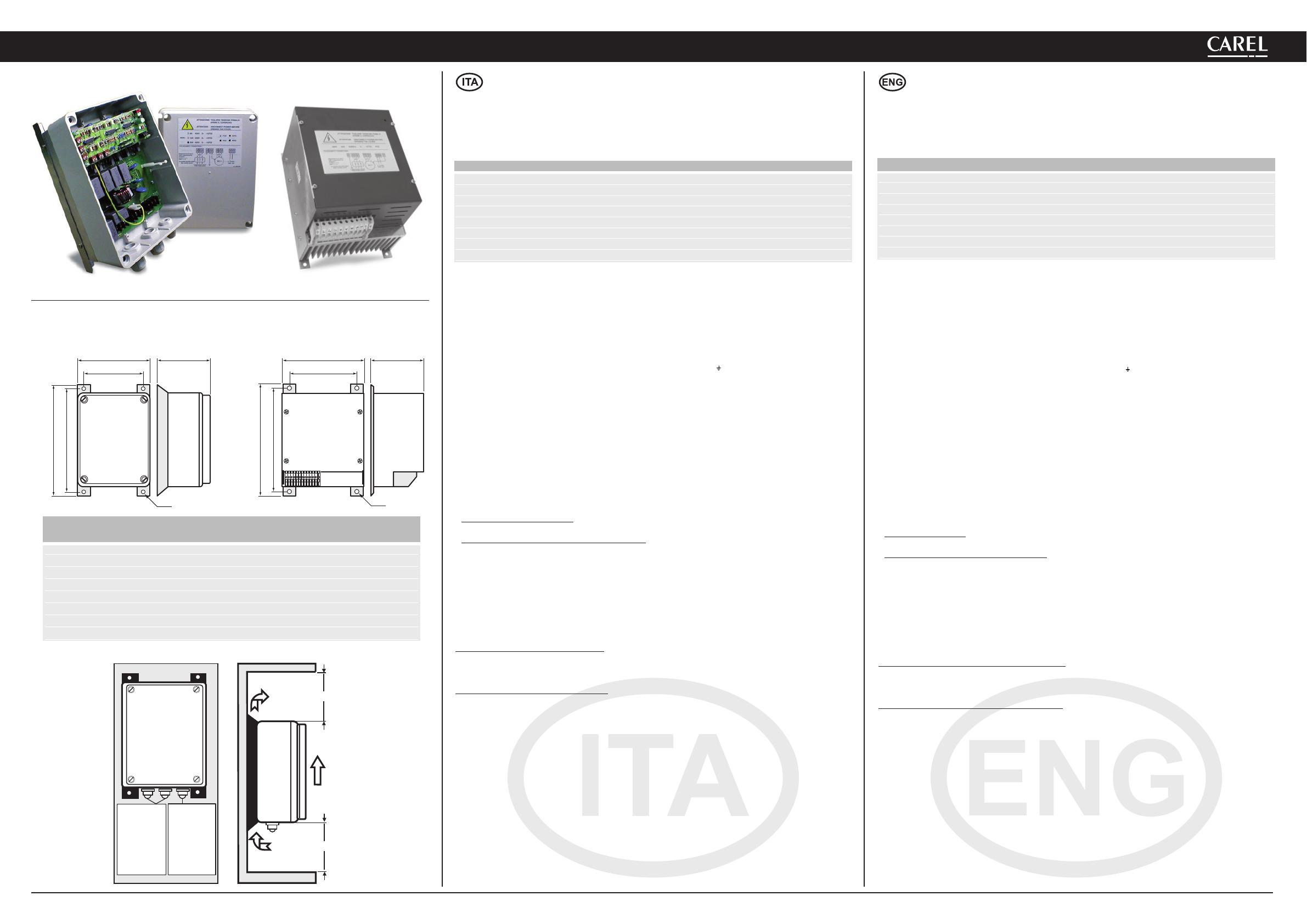
FCS IP55 FCS IP20
AE
DC
DC
B
AE
B
F
F
150 mm
PG
FCS306****
Ø6/12 mm - PG 13,5
FCS312****
Ø 9/14 mm - PG 16
FCS320****
Ø 9/14 mm - PG 16
FCS340****
Ø 15/18 mm - PG 21
PG 9
Ø 4/8 mm
150 mm
Montaggio FCS / Installing FCS
Modelli 230 Vac su richiesta A B C D E F IP
Models 230Vac on request
FCS3064000 (FCS3062300) 153 133 225 200 115 6 55
FCS3124000 (FCS3122300) 205 180 280 255 130 6 55
FCS3204000 (FCS3202300) 198 174 280 255 158 6 55
FCS3404000 (FCS3402300) 245 219 340 315 200 6 55
FCS3094010 (FCS3092310) 170 144 265 250 115 6 20
FCS3124010 (FCS3122310) 170 144 265 250 115 6 20
FCS3204010 (FCS3202310) 198 174 265 250 140 6 20
FCS3404010 (FCS3402310) 198 174 265 250 175 6 20
Dimensioni regolatore FCS (mm) / FCS controller dimensions (mm)
Fig. 1
Fig. 2
FCS IP55 FCS IP20


 Wavecom WMOD2B Manuale utente
 Sentera Controls USV-8-010-PA Mounting Instruction
 Sentera Controls SDX-1-15-DT Mounting Instruction