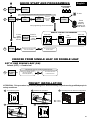
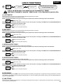
SEA Gate 2 DG R1B Manuale del proprietario
- Categoria
- Gate Opener
- Tipo
- Manuale del proprietario

GATE 2 DG R1B
(Cod. 23023025)
Sistemi Elettronici
di Apertura Porte e Cancelli
International registered trademark n. 804888
®
SEA S.p.A.
Zona industriale 64020 S.ATTO Teramo - (ITALY)
Tel. +39 0861 588341 r.a. Fax +39 0861 588344
www.seateam.com
67411385
Italiano
English
Français
Español
CENTRALE ELETTRONICA PER 1 O 2 MOTORI A 230V/115V
ELECTRONIC CONTROL UNIT FOR 1 OR 2 230V/115V MOTORS
ARMOIRE DE COMMANDE POUR 1 OU 2 MOTEURS EN 230V/115V
CENTRAL ELECTRÓNICA PARA 1 O 2 MOTORES A 230V/115V
Rev.11 - 12/2015

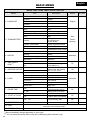
30
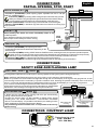
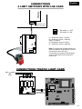
CN1 = Input/output connectors
CN2 = Limit switch, 24V~, Electrolock connector
CN3 = M1 Motors and capacitors connector
CN4 = M2 motors and capacitors connector
CN5 = Courtesy light output connector
CN6 = Power supply connector
CN7 = Encoder connector
CNA = RX Receiver connector
CNP = Porgramming connector
EXP = Expansion module connector / LE Card
JOLLY = Jolly and Jolly 2 connector
DS = Programming display
OK = Programming button
DOWN = Programming button
UP = Programming button
T1 = Motors piloting Triac
T2 = Motors piloting Triac
R1 = Motors comand relay
R2 = Courtesy light comand relay
R3 = Photocell autotest relay
R4 = Electrolock relay
F1 = Accessories 1A fuse
F2 = Fuse 6.3AT on 230V - 10AT on 115V
F3 = 6.3A Electrolock fuse
TR1 = Power transformer
TECHNICAL SPECIFICATIONS
Control unit power supply: 230 Vac 50/60 Hz - 115Vac 50/60 Hz
Absorption in stand by: 30 mA
Environment temperature : -20°C +50°C
Specifications of external enclosure: 325,7 X 246 X 140
RECEIVER RX
168 mm
174 mm
CNP
CN7
EXP
JOLLY
CNA
CN6
CN5
CN4
CN3
CN1 CN2
F1
UP DOWN OK
F2
F3
R2
R1
T1 T2
TR1
R4
R3
DS
JOLLY-JOLLY2
1 2
ON
CN1
CNP
DS1
POTENC
M2
M1
1 2 4
P01 D1 P11 P02 D2 P12 I1
5 6 7
I2
GND
I3 I4
3 8 9 10 11
+ -
LE
(Management card
for linear Encoder)
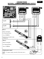
COMPONENTS
English

1
2
3 4
5 6
7 8
9
10
11
12
13
CN1
Start
Stop
Common
Antenna
Partial opening
Common
Loop1 - Photocell 1
Common
ANT COM STRT
STPD
STOP COM PH1 PH2
EDG1
COM 24VA FLS
Safety edge 1
Loop2 - Photocell 2
Flash 24V
(500mA max)
+
-
Safety edge 2
AUX Programmable
(24VDC 800mA
max)
24V~
(800 mA max)
24VPh
(800 mA max)
14
15
16 17
18 19
20 21
22
23
CN2
Electrolock
24
25
26 27
28
CN3
29
30
31 32
33
CN4
M1
M2
NO JUMPERS NEEDED ON N.C. CONTACTS
EDG2
LSO1 LSC1 LSO2 LSC2 COM 24V~
AC
24VPH
AC
LOCK CLM1 NM1 OPM1 CAPM1 CLM2 NM2 OPM2 CAPM2
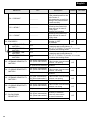
CONNECTIONS
WARNING: Automatic detection of not used N.C. inputs (Photocells, Stop, Limit switch and Edges).
Limit Switch opening M1
Limit Switch closing M1
Limit Switch opening M2
Limit Switch closing M2
Common
Motor 1
opening
Motor 1
closing
Motor 1
Neutral
Capacitor
Motor 1
Motor 2
opening
Motor 2
closing
Motor 2
Neutral
Capacitor
Motor 2
CN6
L N
Line
Nuetral
Not
connected
34 35
CN5
Flash Light
Flash N
31
N.C. Contacts
No need to repeat self programming after reactivation of N.C. contacts.
To reactivate an NC contact you follow this procedure:
Go to press the button for 5 seconds then you enter
the INPUT CHECK MENU, where you can check the operating status of all inputs (pg 40).
MENU
SEA
SET
1-LANGUAGE
OK
24VDC
24VAC
DC
English
THE HEREIN REPORTED FUNCTIONS ARE AVAILABLE STARTING FROM
REVISION 39, ON R1B VERSIONS ONLY.

N.B: For the autotest connect
the transmitters to the
contacts 20 and 21, if you do
not want the autotest connect
the transmitters to the
contacts 19 and 20.
10 11 12 13
1 2 3 4 5 6 7 8 9
CN2
PHOTO
RX1
6
7
6
8
14 15 16 17 18 19 20 21 22 23
14 15 16 17 18 19 20 21 22 23
20
21
19
20
19
20
20
21
CN2
CN1
PHOTO
RX2
PHOTO
TX1
PHOTO
TX2
CONNECTIONS
SAFETY DEVICES
A) 24V AC 19 and 20
19 and 20 24VAC~ (Accessories) 800 mA max COM = 0V
7 PH1 = Photocell contact 1 8 PH2 = Photocell contact 2
Default setting: PHOTO 1 = “Closing” - PHOTO 2 = “Opening and closing”.
The photocell 2 can also be set as TIMER (see TIMER function below).
For the options of the photocells (97 and 98 menus) see page 52-53.
TIMER: by holding PH2 the gate
opens and then stay opened. While you release it the
gate repeat the pause selected time and start closing. In case a safety is
activated the timer will automatically reset after 6 sec.
AUTOTEST Function: Check that the photocells are working properly before
each movement. If the test fails it’s indicated on the display.
To activate AUTOTEST:
1) Connect the TX photocell power on 24V AC~ input 20 and 21
2) Go on 95-PHOTOTEST menu and select on which accessory (Photo 1 or
Photo 2 or both) activate this mode.
PHOTOCELL 1 AND PHOTOCELL 2 - (LOOP1 - LOOP2)
C
B) 24V DC AUX PROGRAMMABLE 12
On the 24VAUX you can select when and how to
operate the connected auxiliary accessory. See
menu 94-24V AUX.
It is not possible to use AUTOTEST if you
connect on 24V DC AUX (only on 24V AC).
The options of 94-24V AUX menu are:
• Always
• In cycle
• Opening
• Closing
• In pause
• Positive brake management
• Negative brake management
• Negative brake management - photocellule
• Gate open warning light
(See special menu pg. 51)
MENU
94-24V AUX
SEA
SET
Max load 800 mA
English
32

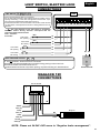
CONNECTIONS
SAFETY EDGE AND FLASHING LAMP
11
10 11 12 13
1 2 3 4 5 6 7 8 9
CN1
EDG2 Safety edge
in opening
9
11
10
13
11
EDG1 Safety edge
in closing
CONNECTIONS COURTESY LIGHT
CN5
34 35
It blinks once per second during opening and twice per second during
closing, while it remains lit during pause.
Throught the warning light it is also possible to identify alarm signals
comming from the STOP, PHOTOCELL 1, PHOTOCELL2 and EDGE
devices. On board display it is possible to activate the pre -flashing function
and/or fixed flashing, defaults signals lamp or Buzzer.
The pre-flashing can be set from 0 to 5 s. or it is possible to have it only
before closing.
33
10 11 12 13
1 2 3 4 5 6 7 8 9
CN1
When pressing this button the motor immediately stops in any
condition/position.
To re-start the movement give a start command.
After a stop the motor always re-starts in closing.
• Function 1 (STANDARD): partial opening space adjustble from 20 to 100 (90-
PARTIAL OPENING menu).
• Function 2 (TIMER): by holding STDP 4 the gate opens and then stay opened.
While you release it the gate repeat the pause selected time and start closing.
In case a safety is activated the timer will automatically reset after 6 sec.
• Function 3 (2 BUTTONS): in 2 buttons logic press the STPD 4 to close the gate.
• Function 4 (DEADMAN): in deadman logic this button executes the re-closing if you
keep it pressed.
PARTIAL OPENING (N.O.) 4
STOP (N.C.) 5
3
6
5
6
STOP
PARTIAL
OPENING
6
4
C
• Function 1 (STANDARD): a
• Function 2 (TIMER): h
In case of activation of a safety device the timer will automatically reset after 6 seconds.
• Function 3 (2 BUTTONS):
• Function 4 (DEADMAN):
n impulse given to this
contact opens and closes the automation depending on the
Selected logic.
To connect the other devices refer to the related instructions leaflets (ie. loop detectors and proximity
Switches).
in deadman logic keep pressed the Start for the opening of the automation.
olding START starts the TIMER function, releasing the start, the operator repeats the pause
V and then close.
in 2 buttons logic this button performs the opening.
START (N.O.) 3
START
-
ANTENNA
Pressing EDG1 and EDG2, the contact opens, causing a partial reversing of the gate in closing and opening.
Note1: the EDG1 and EDG2 inputs can be set: only in closing, only in opening or in both directions.
Note2: It is possible to activate a balanced edge 8K2 through the on board display or through the Jolly programmer, in such
case the edge contact will be controled by a specific resistance value, detecting the possible involontary short circuit of the
device. In case of an imbalanced device a special alarm will show on the on board display or on the JOLLY programmer.
If you connect a wireless edge it is possible to make a self-test on the power
supply of the receiver by connecting it to 24Vac and selecting in the 96-EDGE
AUTOTEST menu the edge or the edges on which to perform the test.
SAFETY EDGE - EDGE 1 9 EDGE 2 10
24V FLASHING LIGHT 3W MAX 13
CONNECTIONS
PARTIAL OPENING, STOP, START
English
Timing from 0 to 4 min
(230V~ 50W Max -
115V~ 50W Max)

Example
Motor 2
Motor 2 connection
M = Opening/Closing
Com = COMMON
Motor 1
Motor 1 connection
M = Opening /Closing
Com = COMMON
Motor to be connected in case
of single-leaf.
M1
M2
Cap M2
Cap M1
Example
POWER SUPPLY INPUT
NOTE: For power supply connection follow the rules in
force
CN4
Phase 1
Neutral
Phase 2
Phase 1
Neutral
Phase 2
CN3
CN4
Line
Neutral
CN3
CN6
24 25 26 27 28 29 30 31 32 33
L N
27
28
32
33
24
25
26
29
30
31
CONNECTIONS
MOTORS, CAPACITY AND POWER SUPPLY
English
34

14 15 16 17 18 19 20 21 22 23
CN2
Does not need a jumper when not connected.
For the limit switch function, limit switches must be installed, both in
opening and closing. In the case of single-leaf connect motor 1 (it is
not necessary to bridge the limit switches of motor 2).
Anti-intrusion function can be activated. This function needs at least
one limit switch, which pushes the motor in closing direction once it’s
released.
The right operation of the limit switch is guaranteed
when the motors turning direction correspond with the
respective employed limit switche.
Com = Common
C= Contact
Limit switch
M1 opening
Limit switch
M1 closing
Limit switch
M2 opening
Limit switch
M2 closing
ELECTROLOCK
A 12V 15W max electrolock can be connected
Electrolock can be deactivated when not used for energy saving on the control unit.
Electrolock release can be timed from 0 to 5 s.
The electrobrake can be set: only before opening, only before closing or in both directions.
N.C.
N.C.
N.C.
14
18
15
18
16
18
22 23
17
18
CONNECTIONS
LIMIT SWITCH, ELECTRIC LOCK
35
!!
N.C.
LIMIT SWITCH 14 15 16 17
ELECTROLOCK OUTPUT 22 23
English
MagLock
MAGLOCK 12V
CONNECTIONS
NOTE: Please set 94-24V AUX menu to “Negative brake management”.
COM
CN1 (11)
1 2 3 4 5 6 7
Art.23105340
24VDC
CN1 (12)
COM
NO
NC
COM
CN2 (18)
12V DC
CN2 (19)

ATTENTION: The first operation after
power failure, will be executed with the
set speed to search the mechanical
stops limit.
1) AMPEROMETRIC DEVICE FOR ELECTROMECHANICAL OPERATORS
This control unit comes with an obstacle detection system working only on electromechanical operators allowing to
have the reversing on obstacles and the automatic detection of the stops.
Sensitivity adjustable from OFF to 99% inside the special menu. The more the percentage is high the more the
obstacle detection will be difficult. On hydraulic unit this parameter will be always OFF.
CONNECTIONS
SAFETY GATE, AMPEROMETRIC MANAGEMENT
or POSITION GATE
2) SAFETY GATE
The Safety Gate, unlike the amperometric sensor, can be used both on
electromechanical and hydraulic operators.
The Safety Gate is an ENCODER allowing the detection of the gate position
and its reversing in case of obstacles. To use the ENCODER it is necessary
to enable it inside the special 32-ENCODER Menu. The sensitivity on the
obstacle is adjustable from 0 - 99%. The higher the percentage is the more it
will be difficult to detect the obstacle.
SAFETY GATE 1
1
3
4
1
3
4
SAFETY GATE 2
1
2
3 4
ENC1+24V ENC2 GND
CN7
2
36
3) POSITION GATE WITH LE CARD
The position gate allows to know the exact position of the gate and to have the reverse on the obstacle.
The position gate is applicable on the hydraulic motors Half Tank and Mini Tank new series, in combination with
the LE card.
To connect position gate (linear Encoder):
If the reading of the potentiometer is reversed relative to the movement of the motor, on the display will appear the
alarm "Potentiometer direction" and you will have to reverse the brown wire with the green one and repeat
programming.
Potentiometer 1 (Position Gate)
Potentiometer 2 (Position Gate)
D2 (White)
P02 (Green)
P12 (Brown)
D1 (White)
P01 (Green)
P11 (Brown)
LE CARD
1 2
ON
CN1
CNP
DS1
POTENC
M2
M1
1 2 4
P01 D1 P11 P02 D2 P12
5 63
+ -
3.1)
3.2)
3.3)
MENU
SEA
SET
32-ENCODER
UP/DOWN
MENU
SEA
SET
POTENTIO-
METER
OK
3.4) Sensitivity adjustment on obstacle reverse from 1 to 100. Go to menu from 38 to 45.
1
ON
OFF
2
English

CONNECTIONS
4 LIMIT SWITCHES WITH LSE CARD
CONTROL UNIT
GATE 2 DG R1B
I1 = Slowdown motor 1 closing
I2 = Slowdown motor 1 opening
GND = Common
I3 =Slowdown motor 2 closing
I4 = Slowdown motor 2 opening
Note: For gates with double leaves only
the limit switches for slowdown must be
connected on the LSE card.
The closing and opening limit switches
must be connected on the electronic
control unit.
37
English
Dip switch 1 = OFF
Dip switch 2 = ON
1 2
ON
OFF
EXP
Display
1 2
ON
CN1
DS1
POTENC
M2
M1
1 2 4
P01 D1 P11 P02 D2 P12 I1
5 6 7
I2
GND
I3 I4
3 8 9 10 11
P01 to P12
NOT USED
NOT USED
LSE CARD
EXP
DS1
DS2
RL4 RL3 RL2 RL1
L4
L3
L2
IC2
- M2+
1 CNP
CN1
L1
M1
24V~ / (ac/dc)
or
230V~
1 2 3 4 5 6 7 8
1
2
3
4
CONNECTIONS TRAFFIC LIGHT CARD
Connect on
EXP terminal

DRAWING SHOWS HOW TO
EVENTUALLY CONNECT THE
MAGNETIC LOOP
CONNECTING SCHEME OF THREE READERS OF MAGNETIC LOOP DETECTORS:
(TWO OF THEM USED AS SECURITY DEVICE AND ONE AS EXIT)
SAFETY LOOP SYSTEM
EXIT LOOP SYSTEM
Safety exit
loop 1
Loop1
Loop2
Loop3
Shadow
loop
Free exit
loop 3
10 11 12 13
1 2 3 4 5 6 7 8 9
-
CN1
C
12
11
7
6
8
6
3
6
Safety exit loop
Connecting scheme of
loop detector 1 reader
7 = Contact photocell 1 (N.C.)
6 = Common
Shadow loop
Connecting scheme of
loop detector 2 reader
8 = Contact photocell 2 (N.C.)
6 = Common
Note: Please set 98-
PHOTOCELL2 - LOOP2
menu to “Shadow loop”.
Free exit loop
Connecting scheme of loop
detector reader
3 = Contact start (n.o.)
6 = Common
C2 C2C1
C1 = CONTACT OPEN
C2 = CONTACT CLOSED
12 = 24 V
11 = 0 V
CONNECTIONS
SAFETY LOOP
38
English
F
S
A Y
E
T
P
O
L
O
E
F
E
I
TR
E
X
OP
L
O
A
HO
SD
W
O
P
LO

PRE SET PARAMETERS AND NO/NC CONTACTS
1
3
UP DOWN
MENU
SEA
SET
4
INIT
MENU
SEA
SET
4
MENU
SEA
SET
- - -
- - - -
- - - -
DISPLAY INPUTS STATUS
Start
Pratial
opening
Stop
Limit
Switch
opening
motor 1
Photocell 1
Photocell 2
Edge 1 Edge 2
Limit
Switch
closing
motor 1
Limit Switch
opening motor 2
Limit Switch
closing motor 2
- When N.C. (Photo, Stop, Limit switch and Edge)
MENU
SEA
SET
-
When not engaged or not wired
MENU
SEA
SET
When cross photo or input is engaged
- When N.O. (Start, Partial opening)
MENU
SEA
SET
-
When input is engaged
MENU
SEA
SET
When input is not engaged
39
2
OF
F
Power OFF
N
O
Power ON
Keep pressed the two buttons and . At the same time put to start initialisation
of the board until you see INIT on the display.
N.C contacts
N.O. contacts
English
All parameters will return to the DEFAULT configuration, see "Default" column in the tables of the menus and
all inputs will display their real state.
All contacts N.C. are automatically turned off if not used (no segment on the display).
If the contacts are connected, on the display they will appear in ON (lit segment).

MENU
Description
Description
Start test
Stop test
Partial opening
start test
Safety edge1
test
Photocell 1
test
Photocell 2
test
M1 Opening
limit switch
test
M1 Closing
limit switch
test
The contact must be a N.O. Contact . When activating the related command
on the display SET lights up, the input works.
If SET is always on, check the wirings.
The contact must be a N.C. Contact. When activating the related command
on the display SET lights up, the input works.
If SET is always on, make sure that the contact is a N.C. Contact
The contact must be a N.C. Contact. When activating the related command
on the display SET lights up, the input works. If SET is always on, make
sure that the contact is a N.C. contact or that the related limit switch is not occupied.
The contact must be a N.O. Contact. When activating the related command
on the display SET lights up, the input works.
If SET is always on, check the wirings.
The contact must be a N.C. Contact. When activating the related command
on the display SET lights up, the input works.
If SET is always on, make sure that the contact is a N.C. Contact
IThe contact must be a N.C. Contact. When activating the related command
on the display SET lights up, the input works.
If SET is always on, make sure that the contact is a N.C. Contact
The contact must be a N.C. Contact. When activating the related command
on the display SET lights up, the input works.
If SET is always on, make sure that the contact is a N.C. Contact
The contact must be a N.C. Contact. When activating the related command
on the display SET lights up, the input works. If SET is always on, make
sure that the contact is a N.C. Contact or that the related limit switch is not occupied.
Exit menu
OK
OK
OK
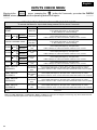
MENU FUNCTION TABLE CHECK GATE 2 DG R1B INPUTS
To access the Menu for input check keep pressed OK for about 5 seconds.
OK
Safety edge2
test
The contact must be a N.C. Contact. When activating the related command
on the display SET lights up, the input works.
If SET is always on, make sure that the contact is a N.C. Contact
OK
M2 Opening
limit switch
test
M2 Closing
limit switch
test
The contact must be a N.C. Contact. When activating the related command
on the display SET lights up, the input works. If SET is always on, make
sure that the contact is a N.C. contact or that the related limit switch is not occupied.
The contact must be a N.C. Contact. When activating the related command
on the display SET lights up, the input works. If SET is always on, make
sure that the contact is a N.C. Contact or that the related limit switch is not occupied.
Note: If the Stop, Photocell 1 and Photocell 2, Edge 1 and Enge 2 contacts are not bridged in self-learning, they will be deactivated and
can be reactivated through this menu, without repeating times self-learning.
LIMIT SWITCH
CLOSING 1
LIMIT SWITCH
OPENING 1
START
EDGE1
PHOTO1
PHOTO2
PARTIAL OPENING START
END
STOP
Enabled
Blocked
LIMIT SWITCH
CLOSING 2
LIMIT SWITCH
OPENING 2
Enabled
Blocked
Enabled
Blocked
Enabled
Blocked
EDGE2
Enabled
Blocked
Moving in the menu pressing the button for 5 seconds, you enter the CHECK
MENU, where you can check the operating status of all inputs.
INPUTS CHECK MENU
MENU
SEA
SET
1-LANGUAGE
OK
40
English

MENU
SEA
SET
MENU
SEA
SET
MENU
SEA
SET
MENU
SEA
SET
1
2
3
PRESS
BUTTON
MENU
SEA
SET
STORED
TRANSMITTERS
START
MOTOR
MENU
SEA
SET
LANGUAGE
MENU
SEA
SET
ENGLISH
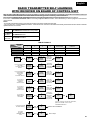
Skip this step if you do not want to program a transmitter
Press the
button of the
TX to be
stored
Choose the type of motor
with UP or DOWN
To confirm and return
to main menu
MENU
SEA
SET
RECEIVER
MISSING
If on the
display
appears
the item:
Check if a
receiver has
been
connceted
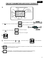
QUICK START AND PROGRAMMING
OK
OK OK
OK
To exit
Press
another
button or
another TX
to be store it
OK OK
SET
UP
UP
UP
OFF
CNA
connector
N
O
Power ONPower OFF
REMOTE CONTROL PROGRAMMING
RX
After programming connect the antenna
PROGRAMMING
BUTTONS
OK
DOWNUP
41
MENU
SEA
SET
OK
ONE SINGLE
LEAF
With UP or DOWN choose
ON only if in single
leaf mode (Motor 1)
To confirm and return
to the main menu
Skip this step if you are working in double leaf mode
4
N
O
A
PRESET INSTALLATION
OFF
Release
Example
M1
M2
ATTENTION: This procedure is potentially dangerous and should only be performed by qualified people in
safety conditions.
Turn OFF the power
B
Release the operators
C
Manually push the leaves in half position
Lock
Example
D
Reset the mechanical lock
E
Put the power ON
M1 = motor1
M2 = motor2
CHOOSE FROM SINGLE LEAF OR DOUBLE LEAF
SET IF ONE SINGLE LEAF (ON)
Default (OFF) = Double leaf
OK
English

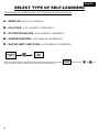
CHOOSE FROM 5 TYPES IN BASE OF TYPE OF YOUR INSTALLATION:
SELECT TYPE OF SELF-LEARNING
A - IMPULSE (MANUAL LEARING)
B - ENCODER (AUTOMATIC LEARNING)
C - POTENTIOMETER (AUTOMATIC LEARNING)
D - AMPEROMETRIC (AUTOMATIC LEARNING)
E - WITH LIMIT SWITCHES (AUTOMATIC LEARNING)
MENU
SEA
SET
9-PROGRAM-
MING
OK
MENU
SEA
SET
ON
* If the motor starts in opening, switch off the power and then ON again, select on the display and through the and put it
on ON, or if you have the Jolly programmer, activate the motor exchange function.
MENU
SEA
SET
5-REVERSE
MOTOR
UP DOWN
42
English

17
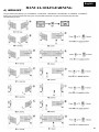
A) IMPULSES *
The gate will start the following cycle: CLOSING M2 - CLOSING M1 - OPENING M1 - OPENING M2 - CLOSING M2 - CLOSING M1.
During cycle, to store the respective stops, press UP or DOWN or START at every point of mechanical stop of the leaf.
The self-learning is done.
MANUAL SELFLEARNING
43
English

- When an Encoder is installed, it is necessary to select ON in the 32-ENCODER menu
Note: to adjust sensitivity on obstacle refer to the special menu to
D) AMPEROMETRIC*
(For electromechanical motors only)
This type of selflearning is possible ONLY with electromechanical operators and physical stops.
E) WITH LIMIT SWITCHES *
1 - INPUT TEST LIMIT SWITCHES: test each limit switch of both leaves by activation before self-learning.
The segment on display shall disappear when each limit switch is activated
MENU
SEA
SET
32-ENCODER
MENU
SEA
SET
ON
MENU
SEA
SET
33-OPENING
SENSITIVITY
MOTOR1
MENU
SEA
SET
37-SLOW DOWN
SENSITIVITY
MENU
SEA
SET
3-MOTOR
MENU
SEA
SET
MECHANIC
REVERSE MOTOR
MENU
SEA
SET
5-REVERSE
MOTOR
* If the motor starts in opening, switch off the power and then ON again, select on the display and through the and put it
on ON, or if you have the Jolly programmer, activate the motor exchange function.
UP
DOWN
MENU
SEA
SET
- - - -
Limit Switch
opening motor 1
Limit Switch
closing motor 1
Limit Switch
opening motor 2
Limit Switch
closing motor 2
AUTOMATIC SELF-LEARNING
WHEN NOT ENGAGED (-) segment is ON
MENU
SEA
SET
WHEN ALL LIMIT SWITCHES
ARE ENGAGED
the segment are in OFF
!!
SELF-LEARNING starts AUTOMATICALLY
MENU
SEA
SET
9-PROGRAM-
MING
OK
MENU
SEA
SET
ON
!!
SELF-LEARNING starts AUTOMATICALLY
2 -
MENU
SEA
SET
9-PROGRAM-
MING
OK
MENU
SEA
SET
ON
!!
SELF-LEARNING starts AUTOMATICALLY
MENU
SEA
SET
45-POT.SLOWDOWN
THRESHOLD
CLOSING2
MENU
SEA
SET
38-POT.
THRESHOLD
OPENING1
C) POTENTIOMETER *
- When the potentiometer is installed, it is necessary to select
Potentiometer treshold intervention is automatically set during self learning, NO NEED TO SET TO
MENU
SEA
SET
9-PROGRAM-
MING
OK
MENU
SEA
SET
ON
MENU
SEA
SET
POTENTIO-
METER
MENU
SEA
SET
32-ENCODER
.
Note: to adjust sensitivity on obstacle refer to the special menu to
MENU
SEA
SET
33-OPENING
SENSITIVITY
MOTOR1
MENU
SEA
SET
37-SLOW DOWN
SENSITIVITY
!!
SELF-LEARNING starts AUTOMATICALLY
B) ENCODER *
MENU
SEA
SET
9-PROGRAM-
MING
OK
MENU
SEA
SET
ON
MENU
SEA
SET
- - -
WHEN SINGLE LIMIT SWITCH
IS ENGAGED
the segment is in OFF
44
Make sure, for all these types of selflearning, that the gate effects the : CLOSE M2, CLOSE M1, OPEN M1,
OPEN M2, CLOSE M2, CLOSE M1.
Otherwise see REVERSE MOTOR function.
following cycle
English
Note: to adjust sensitivity on obstacle refer to the special menu to
MENU
SEA
SET
33-OPENING
SENSITIVITY
MOTOR1
MENU
SEA
SET
37-SLOW DOWN
SENSITIVITY

LOGIC FUNCTIONS
A) AUTOMATIC
A start impulse opens the gate. A second impluse during the opening will not be accepted.
A start impulse during closing reverses the movement.
NOTE 1: To have the automatic closing it is necessary to set a pause time, otherwise all the logic will be semi-automatic.
NOTE2: It is possible to choose, whether to accept or not, the start in pause, selecting in the MENU the item 8-STARTIN PAUSE and
choosing ON or OFF. By default, the parameter is OFF.
B) SECURITY
A start impulse opens the gate. A second impulse during opening reverses the movement.
A start impulse during closing reverses the movement.
NOTE 1: To have the automatic closing it is necessary to set a pause time, otherwise all the logic will be semi-automatic.
NOTE2: It is possible to choose, whether to accept or not, the start in pause, selecting in the MENU the item 8-STARTIN PAUSE and
choosing ON or OFF. By default, the parameter is OFF.
C) STEP BY STEP TYPE 1
The start impulse follows the OPEN-STOP-CLOSE-STOP-OPEN logic.
NOTE 1: To have the automatic closing it is necessary to set a pause time, otherwise all the logic will be semi-automatic.
NOTE2: It is possible to choose, whether to accept or not, the start in pause, selecting in the MENU the item 8-STARTIN PAUSE and
choosing ON or OFF. By default, the parameter is OFF.
D) STEP BY STEP TYPE 2
The start impulse follows the OPEN-STOP-CLOSE -OPEN logic.
NOTE 1: To have the automatic closing it is necessary to set a pause time, otherwise all the logic will be semi-automatic.
NOTE2: It is possible to choose, whether to accept or not, the start in pause, selecting in the MENU the item 8-STARTIN PAUSE and
choosing ON or OFF. By default, the parameter is OFF.
E) DEAD MAN
The gate opens as long as the START button of opening is pressed; releasing it the gate stops. The gate closes as long as the button connected
to the PARTIAL OPENING is pressed; releasing it the gate stops. To execute complete opening and/or closing cycles the related pushbuttons
must be constantly pressed.
F) 2 BUTTONS
One start opens, one partial opening closes. In opening the closing will not be accepted. In closing a start command reopens, a partial opening
command (closes) will be ignored.
MENU
SEA
SET
7-PAUSE
TIME
More than 0 sec
MENU
SEA
SET
8 - START
IN PAUSE
ON (accept start in pause)
OFF (not accept start in pause)
MENU
SEA
SET
7-PAUSE
TIME
More than 0 sec
MENU
SEA
SET
8 - START
IN PAUSE
ON (accept start in pause)
OFF (not accept start in pause)
MENU
SEA
SET
7-PAUSE
TIME
More than 0 sec
MENU
SEA
SET
8 - START
IN PAUSE
ON (accept start in pause)
OFF (not accept start in pause)
MENU
SEA
SET
7-PAUSE
TIME
More than 0 sec
MENU
SEA
SET
8 - START
IN PAUSE
ON (accept start in pause)
OFF (not accept start in pause)
!!
MENU
SEA
SET
6
LOGIC
With UP or DOWN
choose
the desired logic
To confirm and return
to main menu
Skip this step if you want to work
in semi-automatic logic
OK OK
45
ONLY AFTER SELF LEARNING OF WORKING TIME
WITH AUTOMATIC LOGIC, THEN YOU CAN CHANGE LOGICS TO:
English

MENU
Default
SET
Start
Start
Stop
Stop
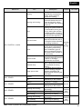
MENU FUNCTIONS TABLE GATE 2 DG R1B
Description
Set value
Italian
English
French
Spanish
2 - TRANSMITTERS
External module
Partial opening
Clear memory
Delete a transmitter
External module
Partial opening
Delete single transmitter
Delete transmitter memory
Olandese
1 - LANGUAGE
Español
English
Français
Italiano
Dutch
English
Start
Partial
opening
End
“Transmitters” menu output
Unloch
Storing of a command
for unlocking an
electric brake
Sliding
Reversible sliding gate
Hydraulic
Mechanic
3 - MOTOR
Sliding
Reversible sliding gate
Hydraulic
Mechanic
Mechanic
4 - ONE SINGLE
LEAF *
Off
On
8 - START IN PAUSE
Disabled
In ON activates single leaf
mode (Motor 1)
6 - LOGIC
Automatic
Open-stop-close-stop-open
2 buttons * *
Safety
Dead man * *
Open-stop-close-open
Automatic
Step by step type 1
Step by step type 2
Two buttons
Safety
Dead man
7 - PAUSE TIME
Setting from 1s to 4min.
OFF
(semi-automatic logics)
9 - PROGRAMMING
10 - TEST START
15 - END
Start command
Times learning start
In pause start is not acceped
In pause start is accepted
Off
Automatic
1 240
Off
Off
On
Off On
Off On
Off
Off
Off
5 - REVERSE MOTOR
Off
On
Off
Press OK to return to the display of the firmware version
and to the one of inputs state.
16 - SPECIAL MENU
Press OK to enter the special menu.
In On reverses the
opening with the closing
and / or vice versa.
* May automatically change depending of motor type.
** You can select those only after having done selflearning with automatic logic.
Off
46
BASIC MENU
English

UPDOWN
SPECIAL MENU
MENU SP
Default
SET
SPECIAL MENU FUNCTIONS TABLE GATE 2 DG R1B
UP and DOWN
UP and DOWN
For entering into the special menu move on one of the menu and press the buttons at the same time
for 5 s or access through the menu 16 and press OK.
For exiting the special menu move on one of the menu and press the buttons at the same time
for 5 s or move on the menu 120 and press OK.
Description
Set value
10 100
10 100
75
75
10 100
10 100
75
75
Off 6
2,5
1,5
Off 20
27 - LEAF DELAY IN
CLOSING *
28 - OPENING TORQ 1 *
29 - CLOSING TORQ 1 *
30 - OPENING TORQ 2 *
31 - CLOSING TORQ 2 *
M1 opening torque
Note: with hydraulic motors
the torque will be on 100%
M2 opening torque
Note: with hydraulic motors
the torque will be on 100%
M2 closing torque
Note: with hydraulic motors
the torque will be on 100%
M1 closing torque
Note: with hydraulic motors
the torque will be on 100%
26 - LEAF DELAY IN
OPENING *
Setting from OFF to
6 seconds
Setting from OFF to
20 seconds
On
xxx.
Encoder impulses during operation
(Motor 1).
Encoder impulses stored in programming
(Motor 1).
In ON enables the
Encoder, in OFF
it's disabled
Encoder impulses during operation
(Motor 2).
Encoder impulses stored in programming
(Motor 2).
Off
32 - ENCODER *
xxx.
xxx.
xxx.
Enables the reading of
the potentiometer with
LE card.
Potentiometer
Reports the current position
of the potentiometer on the
leaf of motor 1.
This parameter is useful for
seeing if the potentiometer
is read correctly.
Reports the impulses
stored by the control unit
when the leaf of motor 1
is fully open.
Reports the impulses stored
by the control unit when the
leaf of motor 1is fully close.
32 - ENCODER *
Off
- - - - - - - -
51 - I.PAR.M1 *
52 - I.AP.M1 *
53 - I.CH.M1 *
- - - - - - - -
- - - - - - - -
48 - ENCODER TOT.1 *
47 - ENCODER PAR.1 *
49 - ENCODER PAR.2 *
50 - ENCODER TOT.2 *
47
English

MENU SP
Default
SET
Description
Set value
Off
32 - ENCODER *
xxx.s
xxx.s
65 - OPENING TIME
MOTOR1
66 - CLOSING TIME
MOTOR1
xxx.s
xxx.s
In ON enables the
Encoder, in OFF
it's disabled
67 - OPENING TIME
MOTOR2
68 - CLOSING TIME
MOTOR2
Indicates the working times selflearning
in opening and closing (Motor 1).
With UP or DOWN it is possible to increase
or reduce the working times.
Indicates the working times selflearning
in opening and closing (Motor 2).
With UP or DOWN it is possible to increase
or reduce the working times.
Off
Reports the impulses
stored by the control unit
when the leaf of motor 2
is fully open.
Reports the impulses
stored by the control unit
when the leaf of motor 2
is fully close.
Reports the current position
of the potentiometer on the
leaf of motor 2.
This parameter is useful for
seeing if the potentiometer
is read correctly.
54 - I.PAR.M2 *
- - - - - - - -
55 - I.AP.M2 *
- - - - - - - -
56 - I.CH.M2 *
- - - - - - - -
33 - OPENING SENSITIVITY
MOTOR1
34 - CLOSING SENSITIVITY
MOTOR1
35 - OPENING SENSITIVITY
MOTOR2 *
36 - CLOSING SENSITIVITY
MOTOR2 *
Off
Off
Off
Off
Disabled
Adjusts the intervention time
of the Encoder / Potentiometer
on Motor 1 in opening
Disabled
Disabled
Off (Intervention excluded)
10% (Fast intervention)
99% (Slow intervention)
10% (Fast intervention)
99% (Slow intervention)
10% (Fast intervention)
99% (Slow intervention)
Off (Intervention excluded)
Off (Intervention excluded)
Disabled
Off (Intervention excluded)
10% (Fast intervention)
99% (Slow intervention)
Adjusts the intervention time
of the Encoder / Potentiometer
on Motor 1 in closing
Adjusts the intervention time
of the Encoder / Potentiometer
on Motor 2 in opening
Adjusts the intervention time
of the Encoder / Potentiometer
on Motor 2 in closing
Off
37 - SLOW DOWN
SENSITIVITY *
Off (Intervention excluded)
10% (Fast intervention)
99% (Slow intervention)
Adjusts the amperometric
sensitivity in slowdown.
Active only if the motors
are electromechanical.
Disabled
48
English
La pagina sta caricando ...
La pagina sta caricando ...
La pagina sta caricando ...
La pagina sta caricando ...
La pagina sta caricando ...
La pagina sta caricando ...
La pagina sta caricando ...
La pagina sta caricando ...
La pagina sta caricando ...
La pagina sta caricando ...
La pagina sta caricando ...
La pagina sta caricando ...
La pagina sta caricando ...
La pagina sta caricando ...
La pagina sta caricando ...
La pagina sta caricando ...
-
 1
1
-
 2
2
-
 3
3
-
 4
4
-
 5
5
-
 6
6
-
 7
7
-
 8
8
-
 9
9
-
 10
10
-
 11
11
-
 12
12
-
 13
13
-
 14
14
-
 15
15
-
 16
16
-
 17
17
-
 18
18
-
 19
19
-
 20
20
-
 21
21
-
 22
22
-
 23
23
-
 24
24
-
 25
25
-
 26
26
-
 27
27
-
 28
28
-
 29
29
-
 30
30
-
 31
31
-
 32
32
-
 33
33
-
 34
34
-
 35
35
-
 36
36


SEA Gate 2 DG R1B Manuale del proprietario
- Categoria
- Gate Opener
- Tipo
- Manuale del proprietario
in altre lingue
- English: SEA Gate 2 DG R1B Owner's manual
- español: SEA Gate 2 DG R1B El manual del propietario
Documenti correlati
-
SEA Gate 2 DG R1 Manuale del proprietario
-
-
-
SEA Slide DG Manuale del proprietario
-
-
-
-
-
SEA Gate 1 DG R2BF Manuale del proprietario
-
Altri documenti
-
Nice Automation Mindy A400 Manuale del proprietario
-
 quiko QK-CE220BATRL4 Manuale utente
-
Nice POA1 Instructions And Warnings For The Fitter
-
Marantec CBX20224H Manuale del proprietario
-
 nologo START-S5PV Manual For The Installer
-
Digicom SNM 46F Manuale utente
-
 quiko QK-CE220RLINV Manuale utente
-
 CET LFM52 Manuale del proprietario
-
CARLO GAVAZZI WSS2BA2BAT Manuale del proprietario
-
CAME DC00EGMA01 Guida d'installazione


