Carel compactSteam Manuale utente
- Categoria
- Umidificatori
- Tipo
- Manuale utente

Integrated Control Solutions & Energy Savings
compactSteam
Manuale d’uso
User manual
Electrode Steam Humidifi er
Umidifi catore a vapore per ambienti residenziali


3
compactSteam +030222070 - rel. 1.2 - 20.12.2010
User manual

4
compactSteam +030222070 - rel. 1.2 - 20.12.2010
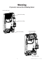
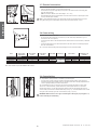
Warning
If present, remove the following items:
Close the cylinder clamp
Remove before installing
Remove before installing
Remove before installing
Remove before installing
Remove before installing

5
compactSteam +030222070 - rel. 1.2 - 20.12.2010
WARNINGS
The CAREL Industries humidi ers are advanced products, whose operation is
speci ed in the technical documentation supplied with the product or can be
downloaded, even prior to purchase, from the website www.carel.com. Each
CAREL Industries product, in relation to its advanced level of technology, requires
setup/con guration/programming/commissioning to be able to operate in
the best possible way for the speci c application. The failure to complete such
operations, which are required/indicated in the user manual, may cause the nal
product to malfunction; CAREL Industries accepts no liability in such cases.
The customer (manufacturer, developer or installer of the nal equipment)
accepts all liability and risk relating to the con guration of the product in order
to reach the expected results in relation to the speci c nal installation and/
or equipment. CAREL Industries may, based on speci c agreements, acts as a
consultant for the installation/commissioning/use of the unit, however in no
case does it accept liability for the correct operation of the humidi er and the
nal installation if the warnings or suggestions provided in this manual or in
other product technical documents are not heeded. In addition to observing
the above warnings and suggestions, the following warnings must be followed
for the correct use of the product:
• DANGER OF ELECTRIC SHOCK
The humidi er contains live electrical components. Disconnect the power
supply before accessing inside parts or during maintenance and installation.
• DANGER OF WATER LEAKS
The humidi er automatically and constantly lls/drains certain quantities of
water. Malfunctions in the connections or in the humidi er may cause leaks.
• DANGER OF BURNS
The humidi er contains high temperature components and delivers steam
at 100°C/ 212°F.
Warning
Warning:
• The installation of the product must include an earth connection, using the
special yellow-green terminal available in the humidi er.
• The environmental and power supply conditions must conform to the values
speci ed on the product rating labels.
• The product is designed exclusively to humidify rooms either directly or
through distribution systems (ducts).
• Only quali ed personnel who are aware of the necessary precautions and
able to perform the required operations correctly may install, operate or carry
out technical service on the product.
• Only water with the characteristics indicated in this manual must be used for
steam production.
• All operations on the product must be carried out according to the instructions
provided in this manual and on the labels applied to the product. Any uses
or modi cations that are not authorized by the manufacturer are considered
improper. CAREL Industries declines all liability for any such unauthorized use.
• Do not attempt to open the humidi er in ways other than those speci ed in
the manual.
• Observe the standards in force in the place where the humidi er is installed.
• Keep the humidi er out of the reach of children and animals.
• Do not install and use the product near objects that may be damaged when
in contact with water (or condensate). CAREL Industries declines all liability
for direct or indirect damage following water leaks from the humidi er.
• Do not use corrosive chemicals, solvents or aggressive detergents to clean
the inside and outside parts of the humidi er, unless speci cally indicated in
the user manual.
• Do not drop, hit or shake the humidi er, as the inside parts and the linings
may be irreparably damaged.
CAREL Industries adopts a policy of continual development. Consequently,
CAREL reserves the right to make changes and improvements to any product
described in this document without prior warning. The technical speci cations
shown in the manual may be changed without prior warning.
The liability of CAREL Industries in relation to its products is speci ed in the
CAREL Industries general contract conditions, available on the website www.
carel.com and/or by speci c agreements with customers; speci cally, to the
extent where allowed by applicable legislation, in no case will CAREL Industries,
its employees or subsidiaries be liable for any lost earnings or sales, losses of data
and information, costs of replacement goods or services, damage to things or
people, downtime or any direct, indirect, incidental, actual, punitive, exemplary,
special or consequential damage of any kind whatsoever, whether contractual,
extra-contractual or due to negligence, or any other liabilities deriving from the
installation, use or impossibility to use the product, even if CAREL Industries or
its subsidiaries are warned of the possibility of such damage.
DISPOSAL
The humidi er is made up of metal parts and plastic parts. In reference to
European Union directive 2002/96/EC issued on 27 January 2003 and the related
national legislation, please note that:
1. WEEE cannot be disposed of as municipal waste and such waste must be
collected and disposed of separately;
2. the public or private waste collection systems de ned by local legislation
must be used. In addition, the equipment can be returned to the distributor
at the end of its working life when buying new equipment;
3. the equipment may contain hazardous substances: the improper use or
incorrect disposal of such may have negative e ects on human health and
on the environment;
4. the symbol (crossed-out wheeled bin) shown on the product or on the
packaging and on the instruction sheet indicates that the equipment has
been introduced onto the market after 13 August 2005 and that it must be
disposed of separately;
5. in the event of illegal disposal of electrical and electronic waste, the penalties
are speci ed by local waste disposal legislation.
Warranty on the materials: 2 years (from the date of production, excluding
consumables).
Approval: the quality and safety of CAREL S.P.A. products are guaranteed by the
ISO 9001 certi ed design and production system, as well as by the
mark.

6
ENGLISH
compactSteam pompa +030222070 - rel. 1.2 - 20.12.2010

7
ENGLISH
compactSteam pompa +030222070 - rel. 1.2 - 20.12.2010
Contents
1. COMPACTSTEAM OPERATION 9
1.1 Operating stages ...................................................................................................................................9
1.2 Cylinder life ............................................................................................................................................10
2. MODELS 11
3. INSTALLATION 12
3.1 Positioning ...............................................................................................................................................12
3.2 Assembly .................................................................................................................................................12
3.3 Characteristics of the supply water ..................................................................................................14
3.4 Drain water .............................................................................................................................................14
3.5 Water connections ................................................................................................................................14
3.6 Steam distribution .................................................................................................................................15
3.7 Electrical connections ...........................................................................................................................18
3.8 Power wiring...........................................................................................................................................18
3.9 Control wiring ........................................................................................................................................18
3.10 On/off operation ..................................................................................................................................19
3.11 Modulating operation .........................................................................................................................20
3.12 Connecting the CLIMA humidistat ..................................................................................................20
3.13 Wiring connections .............................................................................................................................20
4. STARTING 21
4.1 Checks when starting ............................................................................................................................21
4.2 CompactSteam control device ...........................................................................................................21
4.3 Starting compactSteam ........................................................................................................................21
4.4 Starting with a new cylinder ...............................................................................................................21
5. COMPACTSTEAM OPERATION 22
5.1 Displaying information .........................................................................................................................22
5.2 Setting the maximum steam production .........................................................................................22
5.3 Manual drain cycle ................................................................................................................................22
5.4 Resetting the hour counter .................................................................................................................23
5.5 Alarms ......................................................................................................................................................23
6. TROUBLESHOOTING 24
7. MAINTENANCE 25
7.1 Periodical checks ....................................................................................................................................25
7.2 Cylinder maintenance ...........................................................................................................................25
7.3 Spare parts ..............................................................................................................................................26
8. TECHNICAL SPECIFICATIONS 27

8
compactSteam +030222070 - rel. 1.2 - 20.12.2010

9
HL
DP
DT
EVF
8
9
3
13
6
10
2
4
1
11
7
12
5
A
F
B
C
D
E
Fig. 1.a
Fig. 1.b
ENGLISH
compactSteam pompa +030222070 - rel. 1.2 - 20.12.2010
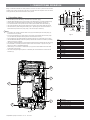
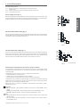
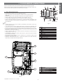
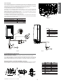
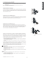
1. COMPACTSTEAM OPERATION
Range of isothermal humidifi ers for steam production in rooms. The steam is produced from the water
contained in the cylinder (connected to the mains). The water boils and evaporates due to the electric
current generated by two immersed electrodes in the cylinder.
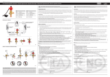
1.1 Operating stages
• the humidifi er opens the fi ll valve (1) connected to the main water supply;
• the water fl ows through the hose (2) to the tank (3), the fl ow restrictor (4) controls the fi lling speed;
• when the tank is full, the water overfl ows into the hose (6) and starts fi lling the cylinder (5);
• once the level of water in the cylinder has been reached, the humidifi er closes the fi ll valve (1);
• the current generated by the immersed electrodes in the cylinder (7) heats the water until it boils;
• the steam exits the cylinder through the outlet (8) and - depending on the model of humidifi er - is
distributed directly into the room (using a fan), or into the duct (via a steam line).
Note:
• if the water in the cylinder exceeds the level sensor (9), the humidifi er opens the drain pump (11)
and drains the excess quantity;
• if the current generated in the cylinder reaches excess levels, the humidifi er opens the drain pump
(11) and drains the quantity of water required to restore the level of current;
• before emptying the humidifi er activates the tempering valve (10) to cool the water to 60°C/140°F;
• the humidifi er automatically controls the quantity of mineral salts dissolved in the water by activating
the fi ll (1) and drain (11) pumps;
• the cylinder is fi tted with a fi lter (12) to prevent the mineral debris from blocking the drain pump (11);
• if the humidifi er is in standby and does not produce steam for more than 3 days (72 hours), the
water in the cylinder is automatically emptied;
• the fi ll tank (3) is connected to an overfl ow hose (13) to prevent contact between the mains water
and the water in the cylinder;
• the current running through the cylinder is controlled by the current transformer connected to the
electrodes (7).
No. Description
A cylinder steam generator
B steam blower (optional)
C user interface/display
D On/Off button
E fi ll and tempering valves
F drain pump
Tab. 1.b
water drain
water fi ll
Key
1 fi ll valve
2 fi ll hose
3 fi ll tank
4 fl ow restrictor
5 cylinder
6 cylinder fi ll hose
7 immersed electrodes
8 steam outlet
9 level sensor
10 tempering valve
11 drain pump
12 water drain fi lter
13 overfl ow hose
Tab. 1.a

10
Fig.1.c
20%100%
ENGLISH
compactSteam pompa +030222070 - rel. 1.2 - 20.12.2010
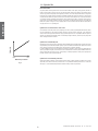
1.2 Cylinder life
Basic information
The plastic cylinder containing the electrodes is the heart of the humidifi er. In the cylinder, during operation, the water is
boiled to produce steam. As the steam does not carry away the minerals dissolved in the water, the concentration of these
increases in proportion to the quantity of steam generated; in addition, some of the salts (above all calcium and magnesium
bicarbonates) tend to foul the electrodes until these are electrically insulated. When a part of the electrodes is covered by lime
scale, the level of the water in the cylinder is raised so that a new section of clean electrodes can conduct the current. At the
end, the electrodes will be completely covered with lime scale and will no longer be able to conduct the current required to
produce steam. The humidifi er controller can measure such low levels of current between the electrodes, and signalling that
the life of the cylinder is coming to an end by displaying alarm code E6. Several factors affect the life of the cylinder, which
may range from 500 to 2000 operating hours.
Cylinder life and characteristics of the water
The characteristics of the water, which vary very depending on the site in question, signifi cantly affect the life of the cylinder.
The main characteristics are the quantity of minerals dissolved in the water and their composition. If, for example, the
content of calcium and magnesium bicarbonates is high, signifi cant deposits form and consequently the life of the cylinder is
shortened. If on the other hand the water contains a considerable percentage of chlorides, corrosion may occur, with possible
electric discharges between the electrodes.
Cylinder life and humidity load
Humidity load demands have an effect on cylinder life. Normal installations where humidity capacity is properly sized require
only intermittent periods where full humidifi er capacity is required. This allows the water level in the cylinder to be increased
only as electrode segments become insulated by lime scale, which tends to maximise cylinder life.
In certain installations that require constant operation at full capacity, cylinder life is reduced because the water level in the
cylinder is generally much higher, and the electrodes become covered with lime scale more quickly. Installations like this may
result in a cylinder life of less than 1000 hours. Consequently, it is extremely important to correctly size the capacity of the
humidifi er in relation to the required humidity load.
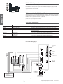
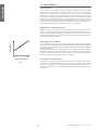
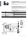
Cylinder life and maximum production
Another factor affecting cylinder life is the maximum production setting. A higher production rate will result in a shorter
cylinder life, and vice-versa. For this reason, models CH*05***** are preset with a maximum production of 70% of the rated
value. Figure 1.c shows the relationship between the maximum steam production and cylinder life.
Cylinder life
Maximum production

11
Fig.2.a
Fig.2.b
ENGLISH
compactSteam pompa +030222070 - rel. 1.2 - 20.12.2010
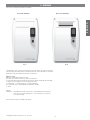
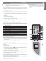
2. MODELS
Two versions of compactSteam humidifi ers are available:
Duct steam distribution Direct room distribution
compactSteam is made in various models that differ in terms of capacity (kg of steam produced per
hour) and voltage (the voltage depends on the national grid). Each model is identifi ed by a 10-character
alphanumeric code. The meaning of each character is shown below:
CH m ss c v xx r
CH means compactSteam Humidifi er and is fi xed;
m = model: 0 for injection in the duct, F for direct room distribution;
ss = rated steam fl ow in kg/h (see the table on page 27 for the complete list with the rated steam fl ow);
c = type of control: V = ON/OFF or 0 to 10 Vdc proportional control;
v = power supply: 1 = 110 VAC single-phase, 2 =230 VAC single-phase;
xx = customisation or xH = complete package (compactSteam + CLIMA);
r = version.
Examples:
CH002V1001: compactSteam for injection in the duct (m = 0), rated steam fl ow 5.5 pounds/hour /
2.5kg/h (ss = 02), 110 VAC single-phase (v = 1), not customised, (xx = 00), version 1
(r = 1, with drain pump)
Note: Some models may not be available in all countries.

12
A
B
C
D
E
F
A
B
C
D
A
B
C
Fig. 3.a
Fig. 3.b
Fig. 3.c
Fig. 3.d
Fig. 3.e
ENGLISH
compactSteam pompa +030222070 - rel. 1.2 - 20.12.2010
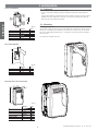
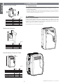
3.1 Positioning
• The compactSteam unit is designed for wall-mounting;
• to ensure correct steam distribution, position the humidifi er near the point of steam distribution
steam;
• make sure the humidifi er is vertical, leaving the minimum clearances (see Fig.3.a and Tab. 3.a for the
installation of the duct model and Fig. 3.b and Tab. 3.b for the room model) to ensure safety and
allow for the necessary maintenance operations.
3.2 Mounting
Removing the front cover
The front cover is fastened to the body unit using four Phillips head screws located in the four corners of
the unit. Use a screwdriver to unscrew the four screws on the cover as shown in Fig. 3.d, then remove
the cover by simply pulling it outwards (Fig. 3.e). To replace the cover, perform the same operations in
the reverse order.
Be careful not to over-tighten the screws.
Duct steam distribution
Direct room distribution
Dimensions of the unit (for all models):
3. INSTALLATION
Millimetres Inches
A
150 mm 6“
B
150 mm 6“
C
150 mm 6“
D
150 mm 6“
E
600 mm 24“
F
max. 0.2
Tab. 3.a
Millimetres Inches
A
150 mm 6“
B
1500 mm 60“
C
1800 mm 72“
D
600 mm 24“
Tab. 3.b
Millimetres Inches
A
341 mm 13.4”
B
204 mm 8.1”
C
600 mm 23.7”
Kilograms Pounds
Empty weight
8 kg 18 lbs
Packaged weight
10 kg 22 lbs
Weight installed + water
12 kg 26 lbs
Tab. 3.c

13
60
[2 3/8]
98,5
[3 7/8]
128
[5]
256
[10 1/8]
128
[5]
448
[17 5/8]
UP
UP
BOTTOM
BOTTOM
36
[1 3/8]
99
[3 7/8]
62
[2 1/2]
53
[2 1/8]
37
78
[3 1/8]
[1 1/2]
102
[4]
600
[23 5/8]
35
[1 3/8]
69
[2 3/4]
48
ø 40
[1 5/8]
ø 50
[2]
ø 23
[7/8]
ø 30
[1 1/8]
[1 7/8]
61
[2 3/8]
16
[5/8]
70
[2 3/4]
65
[2 1/2]
60
[2 3/8]
ø 23
[7/8]
94
[3 5/8]
81
[3 1/4]
50
[2]
9
[3/8]
54
[2 1/8]
24
[7/8]
40
[1 5/8]
38,5
[1 1/2]
Fig. 3.f
ENGLISH
compactSteam pompa +030222070 - rel. 1.2 - 20.12.2010
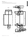
Fastening to the wall
Instructions for fastening to the wall:
1. drill the holes in the wall according to the drilling template supplied;
2. fasten compactSteam to the wall using the screws and the anchors supplied.
Fig 3.f shows the measurements in mm (inches in brackets) for wall-mounting.
TOP

14
ENGLISH
compactSteam pompa +030222070 - rel. 1.2 - 20.12.2010
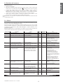
3.3 Characteristics of the supply water
The humidifi er must be supplied with water with the following characteristics:
• pressure between 20psi and 110psi or 0.1 and 0.8 MPa (1 and 8 bar);
• temperature between 33°F and 104°F or 1°C and 40°C;
• fl ow-rate minimum of 0.45 L/min or 0.12gpm;
• connection type
¾” G (see chap. 8 ‘‘Technical specifi cations’);
• hardness no greater than 40°fH (equal to 400 ppm of CaCO
3
);
• conductivity: from 100 to 1250 µS/cm;
• absence of organic compounds.
The characteristics of the supply-water must fall within the following limits:
supply water characteristics unit of
measure
normal
water
water with low
salt content
min. max. min. max.
Hydrogen ions (pH) 7 8.5 7 8.5
Specifi c conductivity at 20 °C (R, 20 °C) µS/cm 350 1250 100 350
Total dissolved solids (cR) mg/l (1) (1) (1) (1)
Dry residue at 180 °C (R180) mg/l (1) (1) (1) (1)
Total hardness (TH) mg/l CaCO
3
100 (2) 400 50 (2) 160
Temporary hardness mg/l CaCO
3
60 (3) 300 30 (3) 100
Iron + Manganese mg/l Fe+Mn = 0.2 = 0.2
Chlorides ppm Cl = 30 = 20
Silica mg/l SiO2 = 20 = 20
Residual chlorine mg/l Cl- = 0.2 = 0.2
Calcium sulphate mg/l CaSO4 = 100 = 60
Metallic impurities mg/l 0 0 0 0
Solvents, thinners, detergents, lubricants mg/l 0 0 0 0
Tab. 3.d
(1)
= values depend on the specifi c conductivity; in general:
C
R
0.65 * R
, 20 °C
; R
18 0
0.93 * R, 20 °C
(2)
= not less than 200% of the chloride content in mg/l CL
-
(3)
= not less than 300% of the chloride content in mg/l CL
-
There is no reliable relationship between hardness and conductivity of the water.
Important
do not treat the water with softeners, this may cause the entrainment of foam, affecting the operation of
the unit;
do not add disinfectants or anticorrosive compounds to the water, as these are potential irritants;
the use of well water, industrial water or water from cooling circuits and, in general, any potentially
chemically or bacteriologically contaminated water is not recommended.
3.4 Drain water
• this contains the same substances dissolved in the supply water, however in higher quantities;
• it is cooled to 60°C / 140°F by mixing it with supply water;
• it is not toxic and can be drained into the sewerage system.
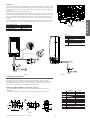
3.5 Water connections
Before proceeding make sure that the humidifi er is disconnected from the main power supply.
Connection to the main water supply
Install a manual valve upstream of the installation to be able to cut off the water supply, as illustrated in Fig.
3.h. Connect the humidifi er to the main water supply using a hose capable absorbing water hammer, to
avoid damaging the fi ll valve. The hoses are identifi ed by the following CAREL codes: FWH3415000 (1.5 m
/4ft long), FWH3 430000 (3 m /9.5ft long ). Alternatively, a hose with a minimum inside diameter of 6 mm
/ 1/4” can be used. If soft polymer tubing is used, secure this to the wall to prevent it from detaching from
the fi ll connector and this avoiding water leaks. The threaded fi ll valve fi tting is located at the bottom of the
humidifi er (see Fig. 3.g). Remember that the fi ll valve is fi tted with a fi lter that requires periodical cleaning.
Make sure there is suffi cient clearance for maintenance. The water line can be connected either through the
holes at the rear (so that these remain hidden behind the unit) or through the holes at the bottom of the unit.
IMPORTANT: When installation is completed, fl ush
the supply hose for around 30 minutes by piping
water directly into the drain, without sending it into the
humidifi er. This will eliminate any scale or processing
residues that may block the drain pump and cause
foam when boiling.

15
4
1
6
2
3
5
min. 5°
4
5
Fig. 3.g
Fig. 3.h Fig. 3.i
F
H
G
I
C
A
B
B
D
I
H
G
F
1
A
A
E
B
A
1
2
2
Fig. 3.j
ENGLISH
compactSteam pompa +030222070 - rel. 1.2 - 20.12.2010
Water drain
As well as the connection to the main water supply, compactSteam also requires connection to a drain
pipe for emptying the water in the cylinder whenever necessary. The drain tubing can be connected from
the rear (as shown in Fig. 3.i) or from the bottom of the unit using the elbow connector supplied (Fig.
3.g and 3.h).
The characteristics of the drain line are shown in Tab. 3.e.
The drain tubing must have a minimum inside diameter of 32 mm (1-1/4”) and must be secured to the
humidifi er drain outlet without requiring additional support. The drain tubing must have a minimum slope
of 5°, and a drain trap must be installed to prevent the return of odors, as illustrated in Fig. 3.h and 3.i.
In addition, a funnel should be used to interrupt continuity in the drain line and prevent fl ooding inside
the unit.
The compactSteam unit is fi tted with a tempering valve that, opening at the same time as the pump, adds
cold water to the drain line, thus ensuring a maximum temperature of the drain water of 60°C /140°F.
Instant drain fl ow 50Hz
25 l/min / 6,6 gpm
Instant drain fl ow 60Hz
26,2 l/min / 7 gpm
Rated connection diameter
32 mm / 1-1/4”
Drain temperature
60 °C / 140 °F
Tab. 3.e
Key:
1 Supply
2 Manual valve
3 External fi lter (recommended)
4 Drain funnel
5 Drain
6 Water fi ll hose
(FWH3415000 or FWH3430000)
Water drain
Fill valve and fi lter
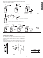
3.6 Steam distribution
Steam injection in the duct
The maximum static pressure allowed in the duct is 950 Pa (95 mm water column /3.7” W.C.)
The compactSteam duct models can be used with the plastic nozzle shown in Figure 3.j (CAREL code
SDPOEM00**) for the injection of steam in the duct. The dimensions are shown in Table 3.f. These
distributors can be fi tted horizontally or vertically (hole facing upwards).
Installing the CAREL SDPOEM00** jet distributors (see Fig.3.j)
- make a series of holes on the wall according to the distributor drilling template (included in the
packaging);
- insert the distributor with the steam opening inside the duct; fasten the fl ange using 4 screws.
Millimetres Inches
A 31.5 mm 12.4”
B
50 mm 1.96”
C
56 mm 2.20”
D
57.5 mm 2.26”
E
100 mm 3.93”
F
Ø 8 mm Ø 0.31”
G
Ø 22 mm Ø 0.86”
H
Ø 30 mm Ø 1.18”
I
12 or 22 mm 0.47 or 0.87”
1
Steam inlet
2
Condensate outlet
Tab. 3.h

16
Fig. 3a.j
Fig. 3.k
ENGLISH
compactSteam pompa +030222070 - rel. 1.2 - 20.12.2010
Alternatively, a stainless steel distributor for ducts can be used (CAREL code DP0**D22R0):
B
Y
X
A
X
l
°2
3
1
2
4
Models
• DP035D22R0: l = 332 mm / 13 1/16” (models CH001 to CH003 only);
• DP045D22R0: l = 438 mm / 17 1/4” (for all models, CH001 to CH005).
Tab. 3.g
Installing the CAREL DP0**D22R0 linear distributors (see Fig. 3a.j):
• make a series of holes on the wall according to the distributor drilling template (included in the
packaging);
• insert the distributor with the steam holes facing upwards;
• fasten the fl ange using 4 screws.
Important: to allow the condensate to return through the drain connection, fi t the distributor at a slight
incline (at least 2°, see Fig. 3.l).
Condensate drain hose
During operation some of the steam may condense, causing a decline in effi ciency and noise (gurgling).
To drain the condensate, connect a drain hose (CAREL code 1312353APG) with a drain trap and a
minimum slope of 5° to the bottom of the humidifi er (see Fig. 3.L). The condensate hose should run
through the hole located at the top of the fi ll tank inside the humidifi er, as illustrated in Fig 3.k.
IMPORTANT WARNING: for correct operation, the drain trap should be fi lled with water before starting
the humidifi er.
Steam hose
• make the connection between the humidifi er and distributor using a hose (it is recommended to use
the steam hoses supplied by CAREL, code 1312360AXX). Unsuitable hoses may weaken and crack
causing steam leaks;
• avoid the formation of pockets or traps where condensate may form;
• avoid choking the hose due to tight bends or twisting.
fasten the end of the hose to the connectors on the humidifi er and the steam distributor using metal
clamps (not supplied), so that these do not detach due to the high temperature.
To connect to the cylinder hose steam use the adapter code
CHKADAP000.
WARNING: the length of the hose must not exceed 4 m / 13ft.
Key to Fig. 3.j:
1
steam inlet (ØA)
2
condensate drain (ØB)
3
fl ange gasket
4
screw max diameter. “M5 / (3/16”) (see instruction
sheet supplied with the distributor)
ØA
22 mm (7/8”)
ØB
10 mm (3/8”)
ØY
58 mm (2 1/4”)
Ø
35 mm (1 3/8”)
X
68 mm (2 11/16”)
STEAM CYLINDER HOSE ADAPTER

17
≥20%
≥5%
≥20% ≥20%
≥5%
1.5 m (5 FT max.)
3 m (10 FT max.)
≥20%
0 m (3 FT max.)
1.5 m (5 FT max.)
1.5 m (5 FT max.)
Fig. 3.l
30%
A
C
B
Fig. 3.m
ENGLISH
compactSteam pompa +030222070 - rel. 1.2 - 20.12.2010
Millimetres Inches
A
150 mm 6“
B
1500 mm 60“
C
600 mm 24“
Tab. 3.h
Figure 3.l shows an example of correct and incorrect installation of the steam hose and condensate drain
hose.
ROOM steam distribution
compactSteam can distribute the steam directly into the room being humidifi ed. For direct humidifi cation,
both the compactSteam with built-in blower (CAREL code CHF*******) and the duct model (code
CH0*******) can be used, the latter connected to a remote room blower (code VRDCHA1000 for 110 Vac
models, and VRDCHA2000 for 230 Vac models).
The following drawing (Fig 3.m) shows the minimum distance that must be observed when installing the
remote steam blower, so as to avoid burning and the condensation of steam on objects such as lights,
electrical equipment, cold surfaces, etc. For further details on the installation and use of the blower, see
the corresponding manual.
no condensate drain
horizontal section
Typical installation if the
unit is above the steam
distributor
condensate
drains
condensate
drain
condensate drain with trap
Note: the height of the trap must exceed the static pressure
of the tubing
steam outlet hose
obstacle
gentle bend
Note:
• The minimum slope of the steam outlet hose in the upwards section must be 20%;
• The minimum slope of the steam outlet hose in the downwards section must be 5% ;
• The maximum length of the hose is 4 m / 13ft.
YES
radius too tight
kinked
sag
no trap
no slope
sag without drain
sag without drain
no condensate drain
NO

18
Fig. 3.q
Fig. 3.p
Fig. 3.n Fig. 3.o
Fig. 3.r
ENGLISH
compactSteam pompa +030222070 - rel. 1.2 - 20.12.2010
3.7 Electrical connections
Before proceeding with the electrical connections:
• make sure that the humidifi er is disconnected from the main;
• check that the unit’s power supply voltage corresponds to the value indicated on the rating plate
inside the electrical panel.
(Note: The tolerance allowed on the rated voltage is -15% +10%);
• the humidifi er power line must be fi tted with a disconnect switch and fuses to protect against short
circuits (to be fi tted by the installer).
Note: To avoid unwanted interference, the power cables should be kept separate from any control
wiring. All the wiring must comply with the national and local electrical standards in force.
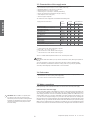
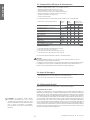
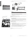
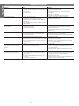
3.8 Power wiring
To connect the humidifi er to the mains:
• once the power cables have been run into the unit, use the cable clamps illustrated in Fig 3.n to
secure them in the correct position;
• connect the power cables to the terminal block at the bottom left of the control module, as illustrated
in Fig. 3.o;
• connect the yellow-green wire to the earth terminal on the unit located on the metal support plate
under the control module.
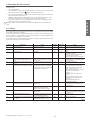
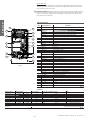
Tab. 3.i shows the electrical data (power supply voltages) for each model of humidifi er.
Code Power supply
(single phase)
Steam output
(kg/h)
Steam output
(Ibs/hr)
Power (kW) Current (A) Power cables External fuse (A)
or breaker
CH*01V1001 110Vac 56/60Hz 1.6 3.5 1.15 10.50 2.5 mm
2
AWG12 16
CH*02V1001 110Vac 56/60Hz 2.5 5.5 1.80 16.40 6 mm
2
AWG10 32
CH*01V2001 230Vac 50/60 hz 1.6 3.5 1.15 5.0 1.5 mm
2
AWG14 10
CH*03V2001 230Vac 50/60 hz 3.2 7 2.31 10.0 2.5 mm
2
AWG12 16
CH*05V2001 230Vac 50/60 hz 5.4 12 3.89 16.9 6 mm
2
AWG10 32
Tab. 3.i
3.9 Control wiring
On compactSteam, steam production is controlled by an external signal:
• in on/off mode, a simple contact (for example a humidistat) enables/disables steam production;
• in proportional mode, the humidifi er produces a quantity of steam that is directly proportional to the
0 to 10 V signal generated by an external control device.
The compactSteam unit can be connected to any simple or automatic humidistat, as well as safety
devices such as limit humidistats, air fl ow switches and remote ON/OFF switches. To connect the
external control devices, run the cables through the bottom of the unit until reaching the top of the
control module, and secure them with the cable clamp (see Fig. 3.n). The terminal blocks for the control
wiring are located at the top right of the control module (see Fig. 3.q and 3.r)
IMPORTANT NOTE: Select the correct type of control signal on the keypad (see paragraph 5.1.1)
before connecting the control wiring.
Note: Some models may not be available in all conutries.

19
N2
GND
N1
AB
AB
GND
IN
H
Fig. 3.t
Fig. 3.s
C R (1)
N2
GND
N1
AB
AB
GND
IN
H
Fig. 3.u
ENGLISH
compactSteam pompa +030222070 - rel. 1.2 - 20.12.2010
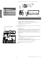
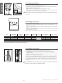
3.10 On/Off operation
The diagrams shown in the fi gures on the side indicate the connections to be performed on the terminal
block in the following situations:
Fig 3.s operation controlled by a simple voltage-free remote enabling contact,
indicated as CR;
Fig 3.t operation controlled by an external mechanical humidistat, indicated as H;
Fig 3.u a combination of the above.
Remote enabling contact (fi g.3.s)
Remove the jumper between terminals AB-AB and connect the voltage-free remote contact (CR) in series
to terminals AB-AB; terminals IN-GND must be jumpered. When contact AB-AB is closed, the humidifi er is
enabled for operation; if the contact is open, steam production stops immediately.
External humidistat without enabling (fi g. 3.t)
Connect the external humidistat between terminals IN-GND and leave the jumper in position between
terminals AB-AB. DO NOT apply any voltage to AB-AB. If the IN-GND contact is closed, steam production
starts, while if it is open steam production stops after 5 s.
External humidistat with enabling (fi g. 3.u)
Connect the external humidistat between terminals IN-GND. Remove the jumper between terminals AB-
AB and connect any limit devices, air fl ow switches or remote contacts (CR) in series to terminals AB-AB.
Steam production only starts when both contacts, AB-AB and IN-GND, are closed. If contact AB-AB is open
steam production stops immediately, while if IN-GND is open production stops after 5 s.
Interlock between compactSteam for ducts and the system fan controller
In duct applications, compactSteam starts steam production only if there is an external call for humidity
(humidistat closed) and the system fan is on. The system fan communicates with compactSteam via the
remote input AB-AB.
The following sequence of events must be true for compactSteam to produce steam:
• External humidistat close (= steam demand)
• FAN-EXT contact closed by compactSteam, to start the system fan
• Input AB-AB closed, indicating that the fan has started (= enable steam production)
compactSteam can be connected to an air fl ow switch (that is, a device that senses the fl ow of air generated
by the fan in the duct). This fl ow sensor should be connected to the remote enabling input (terminals
AB-AB) in series with a limit humidistat (normally closed).
When the fl ow sensor is connected to compactSteam, steam production is only enabled if air fl ow is
measured inside the duct.
Fan symbol
• Off: no call (IN-GND = open), regardless of whether or not production is enabled (AB-AB = open or
closed);
• Flashing: call present (IN-GND = closed), awaiting production to be enabled (AB-AB = open);
• On steady: call present (IN-GND = closed) and production enabled (AB-AB = closed).
Note:
• When enabled (AB-AB = closed), the symbol goes off 30 s after the production call is no longer present
(IN-GND = open);
• When the production call is present (IN-GND = closed), the symbol goes off 60 s after production is
disabled (AB-AB = open).
(1): external switch

20
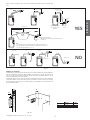
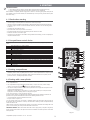
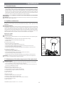
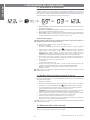
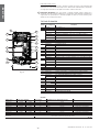
KEY FOR PROGRAMMING PORT:
DP = DRAIN PUMP
DT = DRAIN TEMPERING VALVE
HL = HIGH-LEVEL SENSOR
EVF = FILL VALVE
CONNECTED
TO GROUND
WATER
INLET
POWER SUPPLY
(110VAC 1-PHASE 50-60 HZ
OR
230 VAC 1-PHASE 50-60HZ)
24VAC FOR
EXTERNAL
HUMIDISTATS
EXTERNAL DUCT FAN
ALARM
HUMIDISTAT
AIR PRESSURE SWITCH
PROGRAMMING
PORT
IN GND
AB
AB N1
GND N2
NO
C
NC C NO
24Vac GND
KEYBOARD
EXT FAN
ALARM
KEY
HL
N
EVF
DP
N
F
INT
FAN
E1
E2
L1 L2
8
2
4
EMBEDDED
BLOWER
ON-OFF
BOTTON
6
EXTERNAL FUSED
DISCONNECT TO BE
INSTALLED (NOT
SUPPLIED) RESPECT
LOCAL CODES
HL
STEAM
BOILER UNIT
DP
DT
EVF
WATER
OUTLET
Fig. 3.z
Fig. 3.v
ENGLISH
compactSteam pompa +030222070 - rel. 1.2 - 20.12.2010
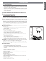
3.11 Modulating operation
Connect the external 0 to 10 V modulating control device between terminals IN-GND as shown in Fig. 3.v.
Then connect any safety switches (limit device, air fl ow switch, remote on/off) in series to terminals AB-AB.
If no safety switches are used, install a jumper between AB-AB. DO NOT apply any voltage to AB-AB.
Steam production is modulated from 20% to 100% of the maximum production, proportionally to the
signal provided by the external controller.
3.12 Connecting the CLIMA humidistat
The Clima humidistat is used to automatically control the humidity in the room. The humidistat can
enable/disable the humidifi er based on two time bands (day and night), and can control humidifi cation in
two different modes: proportional control and ON/OFF control.
For the installation and the connection of the Clima device, see the corresponding instruction sheet,
provided inside the packaging with the humidistat.
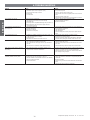
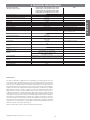
3.13 Wiring connections
Terminal Function Electrical specifi cations
L1-L2-EARTH Power supply and earth connections Power supply (110 Vac single-phase 50/60 Hz or 230 Vac single-phase 50/60 Hz)
KEY Programming port Connection to a programming device or supervisor
AB-AB Remote enabling input Normally open external contact; Rmax= 300 Ohm; Vmax= 33 Vdc; Imax= 6 mAdc;
humidifi er enabled = contact closed
IN-GND Control signal input If 0 to 10 V set:
Input impedance 10 kOhm
If ON/OFF set (default): Vmax = 33 Vdc, Imax = 5mA, Rmax = 300 Ohm
NC-C-NO NC alarm contact
C common alarm contact
NO alarm contact
250 V; 8 Amp max. with resistive load; 4 Amp max. with inductive load
NO-C External fan relay 250 V; 8 Amp max. with resistive load; 4 Amp max. with inductive load
24-GND Power supply for external humidistat Power supply for external humidistat, 24 Vac; 2 Watts
Tab. 3.l
Control device wiring diagram
La pagina si sta caricando...
La pagina si sta caricando...
La pagina si sta caricando...
La pagina si sta caricando...
La pagina si sta caricando...
La pagina si sta caricando...
La pagina si sta caricando...
La pagina si sta caricando...
La pagina si sta caricando...
La pagina si sta caricando...
La pagina si sta caricando...
La pagina si sta caricando...
La pagina si sta caricando...
La pagina si sta caricando...
La pagina si sta caricando...
La pagina si sta caricando...
La pagina si sta caricando...
La pagina si sta caricando...
La pagina si sta caricando...
La pagina si sta caricando...
La pagina si sta caricando...
La pagina si sta caricando...
La pagina si sta caricando...
La pagina si sta caricando...
La pagina si sta caricando...
La pagina si sta caricando...
La pagina si sta caricando...
La pagina si sta caricando...
La pagina si sta caricando...
La pagina si sta caricando...
La pagina si sta caricando...
La pagina si sta caricando...
La pagina si sta caricando...
La pagina si sta caricando...
La pagina si sta caricando...
La pagina si sta caricando...
-
 1
1
-
 2
2
-
 3
3
-
 4
4
-
 5
5
-
 6
6
-
 7
7
-
 8
8
-
 9
9
-
 10
10
-
 11
11
-
 12
12
-
 13
13
-
 14
14
-
 15
15
-
 16
16
-
 17
17
-
 18
18
-
 19
19
-
 20
20
-
 21
21
-
 22
22
-
 23
23
-
 24
24
-
 25
25
-
 26
26
-
 27
27
-
 28
28
-
 29
29
-
 30
30
-
 31
31
-
 32
32
-
 33
33
-
 34
34
-
 35
35
-
 36
36
-
 37
37
-
 38
38
-
 39
39
-
 40
40
-
 41
41
-
 42
42
-
 43
43
-
 44
44
-
 45
45
-
 46
46
-
 47
47
-
 48
48
-
 49
49
-
 50
50
-
 51
51
-
 52
52
-
 53
53
-
 54
54
-
 55
55
-
 56
56


Carel compactSteam Manuale utente
- Categoria
- Umidificatori
- Tipo
- Manuale utente
in altre lingue
- English: Carel compactSteam User manual
Documenti correlati
-
Carel compactSteam XL Manuale utente
-
-
-
-
-
-
Carel humiSteam Basic UE018 Manuale utente
-
-
-
Altri documenti
-
MrSteam Digital 30-Minute Timer Installation & Operation Manual
-
aerauliqa Quantum MX Istruzioni per l'uso
-
Ice-O-Matic 99-05-860 (AF309) Manuale del proprietario
-
aerauliqa QDMEV Istruzioni per l'uso
-
FläktGroup ultimateSAM Manuale del proprietario
-
Tecnosystemi SORRISO LED SCA 15 lt - SORRISO SCA 15 lt under boiler acid condensate water pump Manuale del proprietario
-
 Onninen E2VCABS9I0 Manuale utente
