
ISTRUZIONI DI INSTALLAZIONE
INSTALLATION MANUAL
INSTRUCTIONS D’INSTALLATION
MONTAGEANLEITUNG
INSTRUCCIONES DE INSTALACION
INSTRUÇÕES DE USO E DE INSTALAÇÃO
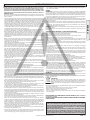
AUTOMAZIONI A BRACCIO PER CANCELLI A BATTENTE
ARM AUTOMATIONS FOR SWING GATES
AUTOMATIONS A BRAS POUR PORTAILS BATTANTS
ARM AUTOMATIONEN FUER FLUGELGITTERTIRE
AUTOMATIZACIONES A BRAZO PARA PORTONES CON BATIENTE
AUTOMATIZAÇÕES DE BRAÇO PARA PORTÕES DE BATENTE
Attenzione! Leggere attentamente le “Avvertenze” all’interno! Caution! Read “Warnings” inside carefully! Attention! Veuillez lire attentivement les Avertissements qui se trouvent à l’intérieur!
Achtung! Bitte lesen Sie aufmerksam die „Hinweise“ im Inneren! ¡Atención¡ Leer atentamente las “Advertencias”en el interior! Atenção! Ler atentamente as “Instruções “ que se encontram no interior!
D811415 ver.09 05-11-15
VIRGO
8
027908 2 2 8 6 8 0

Fig. 1
Fig. 3
Fig. 2
Fig. 5
Fig. 6
SX
300 MIN
30
123
180
215
635
230
Fig. 4
SX
300 MIN
135123
63
63
335
120
90˚
390
230
120˚
390
230
120˚
90˚
Max. 210
335
2 - VIRGO
D811415_09

Fig. 11
Fig. 8
Fig. 10
Fig. 9
Fig. 7
S
S
S
ITALIANO
ENGLISH
FRANÇAIS
DEUTSCH
ESPAÑOL
PORTUGUÊS
VIRGO - 3
D811415_09

Fig. 12
A
C
VIRGO BAT
SBS
4 - VIRGO
D811415_09

Fig. 15
Fig. 16 Fig. 17
LINX
JP1
(+)*
(-)*
ITALIANO
ENGLISH
FRANÇAIS
DEUTSCH
ESPAÑOL
PORTUGUÊS
VIRGO - 5
D811415_09

Fig. 4Fig. 18
Fig. 19
LINX
UNIDA
UNIFLAT
8 8 8 8
S
1
32
Conector programador palmar.
6 - VIRGO
D811415_09

ENGLISH
INSTALLATION MANUAL
+
OK
Fig. A
OK
Press the OK key
BFT
LINX 1.0
0000
0000
00
PARAM
LOGIC.
OK
+/-
+/-
OK
ACCESS TO MENUS
FOLLOWING MENUS
FIG. B
OK
8888
-
+
-
+
Control unit software version
No. total manoeuvres
(in thousands)
No. manoeuvres since latest
maintenance(in thousands)
No. radio control devices
memorised
LEGENDA
[ 00 ] Preset value
Parameter increment/reduction
or ON/OFF commutation
Menu scrolling
(+ = preceding - = following)
Press OK key (Enter/confirm)
Message: Programming in progress
PRG
OK
+/-
-
+
/ON
/OFF
Message: KO! (value or function error)
Simultaneously press the + and - keys.
Simultaneous pressure of the + and – keys allows
you to exit the active menu and return to the
preceding menu; if this takes place at the main
menu level, programming is exited and the display
switched off.
The modifications made are only confirmed if the
OK key is subsequently pressed.
+/-
END
+/-
END
Message: “Wait” (enter value or function)
-
+
-
+
-
+
-
+
-
+
-
+
-
+
-
+
-
+
-
+
-
+
-
+
OK
TCA
ON
OFF
[oFF]
OK
PRG
OK
3 step
ON
OFF
[off]
OK
PRG
OK
ibl open
ON
OFF
[off]
OK
PRG
OK
fast cls
ON
OFF
[off]
OK
PRG
OK
Fotoc. open
ON
OFF
[off]
OK
PRG
OK
TEST PHOT
ON
OFF
[off]
OK
PRG
OK
SCA 2ch
ON
OFF
[off]
OK
PRG
OK
i Mot ON
ON
OFF
[off]
OK
PRG
OK
BLOC persist
ON
OFF
[off]
OK
PRG
OK
Preal
ON
OFF
[off]
OK
PRG
OK
radio prog
ON
OFF
[on]
OK
PRG
OK
fixed code
ON
OFF
[off]
OK
PRG
OK OK
TCA
[0010]
PRG
-
+
OK
change mot
ON
OFF
[off]
OK
PRG
-
+
-
+
-
+
-
+
-
+
-
+
OK OK
[0050]
PRG
m1 t
OK OK
[0050]
PRG
m2 t
OK OK
[0045]
PRG
m1 t slow
-
+
-
+
OK OK
[0045]
PRG
m2 t slow
OK OK
[0010]
PRG
open delay time
OK OK
cls delay
time
[0010]
PRG
OK OK
m1 fast time
[0050]
PRG
OK OK
[0050]
PRG
OK OK
slow speed
[0000]
PRG
m2 fast time
VIRGO - 15
D811415_09

INSTALLATION MANUAL
Fig. B
DEFAULT
RADIO
AUTOSET MENU
It automatically sets the motor torque.
WARNING! During the autoset phase, the obstacle
detection function is not active, therefore the installer
must control the automation movement and prevent
persons and things from approaching or standing
within the automation working range.
PRECEDING MENUS
FIG. A
OK
OK
-
+
-
+
-
+
-
+
+/-
END
+/-
END
OK
+/-
. . . . . .
OK
AUTOset
+/-
END
language
ITA
FRA
DEU
ENG
esp
OK OK
OK
OK
OK
OK
+/-
END
-
+
-
+
-
+
-
+
OK
OK
PRG
Press P1 (pushbutton) on radio
control device
Press the required T (key) on
radio control device – see Fig. B3
Press the required T (key) on
radio control device – see Fig. B3
Release P1 on radio
control device
ADD start
hidden button release
desired button
01
PRG.
READ
OK
OK
OK
ERASE 64
-
+
-
+
Press P1 (pushbutton) on radio
control device
Press the required T (key) on
radio control device – see Fig. B3
Release P1 on radio
control device
ADD 2ch hidden button release
desired button
01
OK
-
+
01 t1
COD RX
OK
1A9C
OK
22FD
OK
01
OK
-
+
+/-
RADIO MENU
ADD - Allows you to add one key of a radio control
device to the receiver memory; after storage it displays
a message showing the receiver number in the
memory location (from 01 to 64).
Add Start button – associates the required key to
Start command
Add 2ch button – associates the required key to 2nd
radio channel
READ - Checks one key on a receiver, if stored it
displays a message showing the receiver number in
the memory location (from 01 to 64), and the key
number (T1, T2, T3 or T4).
ERASE 64
WARNING! Completely removes all memorised radio
control devices from the receiver memory.
COD RX
Displays the receiver code.
Make reference to paragraph 11.
16 - VIRGO
D811415_09

ENGLISH
INSTALLATION MANUAL
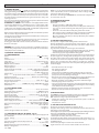
INSTALLER WARNINGS
Anything that is not explicitly provided for in the installation ma-
nual is not allowed. The operator’s proper operation can only be
guaranteed if the information given is complied with. The Firm shall
not be answerable for damage caused by failure to comply with the
instructions featured herein.
While we will not alter the product’s essential features, the Firm reserves
the right, at any time, to make those changes deemed opportune to
improve the product from a technical, design or commercial point of
view, and will not be required to update this publication accordingly.
WARNING! Important safety instructions. Carefully read and comply with
all the warnings and instructions that come with the product as incorrect
installation can cause injury to people and animals and damage to property.
The warnings and instructions give important information regarding safety,
installation, use and maintenance. Keep hold of instructions so that you can
attach them to the technical le and keep them handy for future reference.
GENERAL SAFETY
This product has been designed and built solely for the purpose indicated herein.
Uses other than those indicated herein might cause damage to the product and
create a hazard.
- The units making up the machine and its installation must meet the requirements
of the following European Directives, where applicable: 2004/108/EC, 2006/95/
EC, 2006/42/EC, 89/106/EC, 99/05/EC and later amendments. For all countries
outside the EEC, it is advisable to comply with the standards mentioned, in ad-
dition to any national standards in force, to achieve a good level of safety.
- The Manufacturer of this product (hereinafter referred to as the “Firm”) disclaims
all responsibility resulting from improper use or any use other than that for
which the product has been designed, as indicated herein, as well as for failure
to apply Good Practice in the construction of entry systems (doors, gates, etc.)
and for deformation that could occur during use.
- Installation must be carried out by qualied personnel (professional installer,
according to EN 12635), in compliance with Good Practice and current code.
- Before installing the product, make all structural changes required to produce
safety gaps and to provide protection from or isolate all crushing, shearing and
dragging hazard areas and danger zones in general in accordance with the
provisions of standards EN 12604 and 12453 or any local installation standards.
Check that the existing structure meets the necessary strength and stability
requirements.
- Before commencing installation, check the product for damage.
- The Firm is not responsible for failure to apply Good Practice in the construction
and maintenance of the doors, gates, etc. to be motorized, or for deformation
that might occur during use.
- Make sure the stated temperature range is compatible with the site in which the
automated system is due to be installed.
- Do not install this product in an explosive atmosphere: the presence of ammable
fumes or gas constitutes a serious safety hazard.
- Disconnect the electricity supply before performing any work on the system.
Also disconnect buer batteries, if any are connected.
- Before connecting the power supply, make sure the product’s ratings match the
mains ratings and that a suitable residual current circuit breaker and overcurrent
protection device have been installed upline from the electrical system. Have
the automated system’s mains power supply tted with a switch or omnipolar
thermal-magnetic circuit breaker with a contact separation that provide full
disconnection under overvoltage category III conditions.
- Make sure that upline from the mains power supply there is a residual current
circuit breaker that trips at no more than 0.03A as well as any other equipment
required by code.
- Make sure the earth system has been installed correctly: earth all the metal parts
belonging to the entry system (doors, gates, etc.) and all parts of the system
featuring an earth terminal.
- Installation must be carried out using safety devices and controls that meet
standards EN 12978 and EN 12453.
- Impact forces can be reduced by using deformable edges.
- In the event impact forces exceed the values laid down by the relevant standards,
apply electro-sensitive or pressure-sensitive devices.
- Apply all safety devices (photocells, safety edges, etc.) required to keep the
area free of impact, crushing, dragging and shearing hazards. Bear in mind the
standards and directives in force, Good Practice criteria, intended use, the instal-
lation environment, the operating logic of the system and forces generated by
the automated system.
- Apply all signs required by current code to identify hazardous areas (residual
risks). All installations must be visibly identied in compliance with the provisions
of standard EN 13241-1.
- Once installation is complete, apply a nameplate featuring the door/gate’s data.
- This product cannot be installed on leaves incorporating doors (unless the motor
can be activated only when the door is closed).
- If the automated system is installed at a height of less than 2.5 m or is accessible,
the electrical and mechanical parts must be suitably protected.
- For roller shutter automation only
1) The motor’s moving parts must be installed at a height greater than 2.5 m
above the oor or other surface from which they may be reached.
2) The gearmotor must be installed in a segregated and suitably protected space
so that it cannot be reached without the aid of tools.
- Install any xed controls in a position where they will not cause a hazard, away
from moving parts. More specically, hold-to-run controls must be positioned
within direct sight of the part being controlled and, unless they are key operated,
must be installed at a height of at least 1.5 m and in a place where they cannot
be reached by the public.
- Apply at least one warning light (ashing light) in a visible position, and also
attach a Warning sign to the structure.
- Attach a label near the operating device, in a permanent fashion, with informa-
tion on how to operate the automated system’s manual release.
- Make sure that, during operation, mechanical risks are avoided or relevant
protective measures taken and, more specically, that nothing can be banged,
crushed, caught or cut between the part being operated and surrounding parts.
- Once installation is complete, make sure the motor automation settings are
correct and that the safety and release systems are working properly.
- Only use original spare parts for any maintenance or repair work. The Firm dis-
claims all responsibility for the correct operation and safety of the automated
system if parts from other manufacturers are used.
- Do not make any modications to the automated system’s components unless
explicitly authorized by the Firm.
- Instruct the system’s user on what residual risks may be encountered, on the
control systems that have been applied and on how to open the system manu-
ally in an emergency. give the user guide to the end user.
- Dispose of packaging materials (plastic, cardboard, polystyrene, etc.) in accord-
ance with the provisions of the laws in force. Keep nylon bags and polystyrene
out of reach of children.
WIRING
WARNING!
For connection to the mains power supply, use: a multicore cable with
a cross-sectional area of at least 5x1.5mm
2
or 4x1.5mm
2
when dealing with three-
phase power supplies or 3x1.5mm
2
for single-phase supplies (by way of example,
type H05 VV-F cable can be used with a cross-sectional area of 4x1.5mm
2
). To con-
nect auxiliary equipment, use wires with a cross-sectional area of at least 0.5 mm
2
.
- Only use pushbuttons with a capacity of 10A-250V or more.
-
Wires must be secured with additional fastening near the terminals (for example,
using cable clamps) in order to keep live parts well separated from safety extra
low voltage parts.
-
During installation, the power cable must be stripped to allow the earth wire
to be connected to the relevant terminal, while leaving the live wires as short
as possible. The earth wire must be the last to be pulled taut in the event the
cable’s fastening device comes loose.
WARNING!
safety extra low voltage wires must be kept physically separate from
low voltage wires.
Only qualied personnel (professional installer) should be allowed to access
live parts.
CHECKING THE AUTOMATED SYSTEM AND MAINTENANCE
Before the automated system is nally put into operation, and during maintenance
work, perform the following checks meticulously:
- Make sure all components are fastened securely.
- Check starting and stopping operations in the case of manual control.
- Check the logic for normal or personalized operation.
-
For sliding gates only: check that the rack and pinion mesh correctly with 2 mm
of play along the full length of the rack; keep the track the gate slides on clean
and free of debris at all times.
-
For sliding gates and doors only: make sure the gate’s running track is straight
and horizontal and that the wheels are strong enough to take the weight of the
gate.
-
For cantilever sliding gates only: make sure there is no dipping or swinging
during operation.
- For swing gates only: make sure the leaves’ axis of rotation is perfectly vertical.
-For barriers only: before opening the door, the spring must be decompressed
(vertical boom).
-
Check that all safety devices (photocells, safety edges, etc.) are working properly
and that the anti-crush safety device is set correctly, making sure that the force
of impact measured at the points provided for by standard EN 12445 is lower
than the value laid down by standard EN 12453.
- Impact forces can be reduced by using deformable edges.
-
Make sure that the emergency operation works, where this feature is provided.
- Check opening and closing operations with the control devices applied.
-
Check that electrical connections and cabling are intact, making extra sure that
insulating sheaths and cable glands are undamaged.
- While performing maintenance, clean the photocells’ optics.
-
When the automated system is out of service for any length of time, activate the
emergency release (see “EMERGENCY OPERATION” section) so that the operated
part is made idle, thus allowing the gate to be opened and closed manually.
-
If the power cord is damaged, it must be replaced by the manufacturer or their
technical assistance department or other such qualied person to avoid any risk .
-
If “D” type devices are installed (as dened by EN12453), connect in unveried
mode, foresee mandatory maintenance at least every six months
-
The maintenance described above must be repeated at least once yearly or at
shorter intervals where site or installation conditions make this necessary.
WARNING!
Remember that the drive is designed to make the gate/door easier to use and
will not solve problems as a result of defective or poorly performed installation
or lack of maintenance
SCRAPPING
Materials must be disposed of in accordance with the regulations in
force. Do not throw away your discarded equipment or used batteries
with household waste. You are responsible for taking all your waste
electrical and electronic equipment to a suitable recycling centre.
DISMANTLING
If the automated system is being dismantled in order to be reassembled at another
site, you are required to:
- Cut o the power and disconnect the whole electrical system.
- Remove the actuator from the base it is mounted on.
- Remove all the installation’s components.
-
See to the replacement of any components that cannot be removed or happen
to be damaged.
DECLARATIONS OF CONFORMITY CAN BE FOUND AT http://www.bft-
automation.com/CE
INSTRUCTIONS FOR USE AND ASSEMBLY CAN BE FOUND IN THE DOWN-
LOAD SECTION.
AVVERTENZE PER L’INSTALLATORE D811766_13
VIRGO - 17
D811415_09

INSTALLATION MANUAL
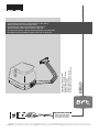
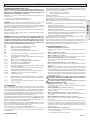
2) GENERAL OUTLINE
Low-voltage operator (24V
) suitable for residential use. Designed for
swing gates having small-sized pillars. The operating arm, with its special
antishearing shape, allows the leaves to be manoeuvred even when the
operator is positioned well away from their fulcrum. The irreversible
electromechanical gearmotor keeps the gate locked in the closing and
opening positions.
The release lever, tted to the outside of each operator, allows the manual
manoeuvre to be carried out very easily.
ATTENTION! The VIRGO model controller is not equipped with mecha-
nical torque adjustment. It is compulsory to use a control panel of the
same manufacturer, in compliance with the basic safety requirements
of directives 2006/95/CEE, 2004/108/CEE, 2006/42/CEE equipped with
appropriate electric adjusment of the torque.
Before carrying out the manual manoeuvre make sure that this operation
will not create a dangerous situations.
Check in the relevant literature that the thermal eld in the working area
is suitable for the operator.
Make sure that the movement of the door does not cause entrapment
risks between the movable and xed parts of the door.
If swing gates with built-in doors are used, the motor must not run when
the door is left open.
WARNING! The operator must be installed by a qualied technician as
special safety components are used for every specic site and therefore
safety depends on installation.
3) TECHNICAL SPECIFICATIONS
3.1) VIRGO OPERATOR
Motor: ..........................................................................................24V
2500 min
-1
Power: .................................................................................................................. 110W
Insulation class: .......................................................................................................... F
Lubrication: ................................................................................ Permanent grease
Reduction ratio: .............................................................................................. 1-1224
Output shaft revolutions: .................................................................2 min
-1
MAX
Opening time 90°: ................................................................................................ 14s
Torque supplied: ..........................................................................................170 Nm
Max leaf weight and length: ....................2000N (~200kg) for 2m long leaf
Impact reaction: ......................................................... Integrated torque limiter
.................................................................................................on LINX control panel
Motion drive: ............................................................................................. Lever arm
Stop: ................ Incorporated electrical limit switches + mechanical locks
Manual manoeuvre: ...............................................Release lever with CLS key
Number of manoeuvres in 24h: ........................................................................ 60
Environmental conditions: ................................................... from -15 to +50 °C
Degree of protection:........................................................................................ IPX4
Operator weight: ......................VIRGO:80N (~8kg) - VIRGO SQ:60N (~6kg)
Dimensions: ................................................................................................... see g.1
3.2) LINX CONTROL PANEL
Power supply: ....................................................................... 230V~ ±10% 50Hz*
Mains/low voltage insulation: ............................................> 2MOhm 500Vdc
Working temperature ............................................................from -15 to +50 °C
Dielectric strength: ....................................... mains/l.v. 3750V~ for 1 minute
Motor output current: .................................................................3.5A+3.5A max
Motor relay commutation current: .............................................................. 10A
Maximum motor power: ...............................................................110W (24V
)
Power supply for accessories: ...................24V~ (180mA max absorption)
......................................................................24V~ safe (180mA max absorption)
Gate-open warning light: .................................N.O. contact (24V~/1A max)
Blinker: ..............................................................................................24V~ 25W max
Dimensions: ...........................................................................................see gure 1
Fuses: ........................................................................................................ see g.9-15
(*other voltages available on request)
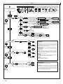
3.3) VIRGO BAT BATTERY KIT (OPTIONAL - Fig.14)
Allows operation to continue even when the mains power supply is o
for a short time.
Charge voltage: .............................................................27.2V
Charge cur-
rent: ...................................................................................................................130mA
Data detected with external temperature of: ......................................... 25°C
Battery capacity: .............................................................................2x (12V 1.2Ah)
Exhausted battery protection threshold: ..........................................20.4V
Battery recharge time: ............................................................................... 12/14 h
NOTE: In case of operation with battery back up, the outputs to termi-
nals 8-9 (Vsafe 24V~) and 10-11 (Vsafe 24V~) show a voltage of 24V
polarised as indicated in Fig.16.
At the time of installing the VIRGO BAT Kit, check that the safety devices
are connected correctly.
4) OPERATOR INSTALLATION
4.1) Preliminary checks
Check that:
• Thegatestructureissucientlysturdyandrigid.
The xing position must be worked out according to the leaf structu-
re. In any case, the manoeuvring arm must push against a reinforced
leaf point.
• Theleavescanbemovedmanuallyalongtheirentirestroke.
If the gate has not been installed recently, check the wear condition of
all its components. Repair or replace defective and worn parts.
Operator reliability and safety are directly aected by the condition
of the gate structure.
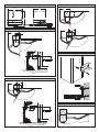
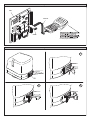
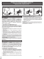
5) SUPPORT PLATE FIXING (Fig.5)
The operator is supplied with a xing bracket and lever arm.
Having identied the leaf reinforcement point, with the gate closed,
trace an imaginary horizontal line from the centre of the reinforcement
point to the pillar (g. 3-4).
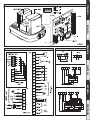
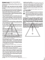
Fig. 2 illustrates the most common types of installation:
- with the leaf hinge pivot not aligned with the xing plate (90° opening
- maximum distance between hinge pivot and plate: 210mm).
- with the hinge pivot aligned with the xing plate
Position the anchoring bracket observing the dimensions shown in g.3
for opening up to 90°, or in g.2-4 for opening over 90° up to a max of 120°.
Thepillarsurface,wherethebracketisxed,mustbeatandparallel
to the leaf. Use screws and expansion plugs adequate for the type of
pillar. In the case where the pillar surface is irregular, use expansion
plugs with studs, in order to be able to adjust the xing bracket parallel
to the leaf (g.5).
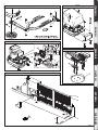
• Assembletheleverarmasing.7.
DX = tting to right leaf
SX = tting to left leaf
Choose the most suitable position for xing bracket “F” to the leaf.
• InsertleverLintothegearmotoroutputshaft,andxitusingappro-
priate pivot P and self-locking nut D (g.7).
• Releasetheoperatorbyactivatingthereleaselevertoallowthearm
to move easily (see paragraph “EMERGENCY MANOEUVRE”).
• OpenthegearmotorcoverandxittotheplateasindicatedinFig.8.
• Fixtowinganglebar“F”totheleaf.
• Thecorrectpositionfortheoperatorarmisillustrateding.6.Theleaf
attachment point can be identied by positioning the arm according
to the dimension indicated in g.6.
• Withtheoperatorreleased,checkthearmforcorrectmovement.
• Repeatthesameprocedurefortheotherleaf.
6) BACKSTOP FIXING
The VIRGO operator is provided with mechanical end-of-stroke backstops,
which make the installation of ground stop plates redundant.
With reference to Fig. 10 proceed as follows:
- Identify the opening and closing end-of-stroke points and x the
backstops accordingly.
- Fix protection cover C.
7) ELECTRICAL INSTALLATION SET-UP
Arrange the electrical installation as shown in g.11.
Keep the mains voltage connections denitely separate from the very
low voltage connections (24V).
For this purpose, the operator is provided with appropriate ttings, indicated
inFig.9,foraspiralexibleracewaywithaninsidediameterof20:
- P1 input for mains power supply + GND.
- P2/P3 inputs for safety devices and accessories.
For the mains power supply, use the appropriate cable clamp (Fig.9 -”S”),
the terminal bar with an incorporated protection fuse (Fig.9 -”L-N”) and
the GND terminal.
Connect the yellow/green cable to the earth terminal.
Fig.16 shows the cross-section and the number of connections.
18 - VIRGO
D811415_09

ENGLISH
INSTALLATION MANUAL
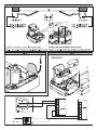
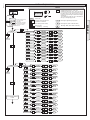
8) TERMINAL BAR CONNECTIONS (Fig.16)
NOTE: The VIRGO operators provided with incorporated LINX control
panels are preset for tting to the left leaf, whereas the operators
without panels (VIRGO-SQ) are preset for tting to the right leaf, as
illustrated by the example given in Fig.11.
Should it be necessary to reverse the operator opening direction, pro-
ceed as follows:
1 – Reverse motor polarity (JP1 terminals 1-2)
2 – Reverse motor polarity (JP2 terminals 14-15)
WARNING – During the wiring and installation operations, refer to the
current standards as well as principles of good technical practice.
The (24V) very low voltage conductors must be physically separated
from the low voltage conductors or otherwise be adequately isolated
by means of an additional insulation of at least 1 mm.
The wires must be clamped by an extra fastener near the terminals, for
example by bands.
All the connection cables must be kept at an adequate distance from
the dissipator(Fig.15 “D”).
WARNING! For connection to the mains, use a multipolar cable with
a minimum of 3x1.5mm
2
cross section and complying with the pre-
viously mentioned regulations. For example, if the cable is out side
(in the open), it has to be at least equal to H07RN-F, but if it is on the
inside (or outside but placed in a plastic cable cannel) it has to be
or at least egual to H05VV-F with section 3x1.5mm
2
.
JP1
1-2 Motor 2 connection (VIRGO with LINX panel):
3-5 Opening limit switch SWO M2 (N.C.)
4-5 Closing limit switch SWC M2 (N.C.)
6-7 24 V~ power supply input from the transformer
JP2
8-9 24V~ Vsafe 180mA max output – power supply for photocell
transmitters with check (Fig.17)
10-11 24V~ 180mA max output – power supply for photocells or
other devices
12-13 Blinker connection (24V~ 25W max)
14-15 Motor 1 connection (VIRGO-SQ – without LINX panel -):
16-18 Opening limit switch SWO M1 (N.C.)
17-18 Closing limit switch SWC M1 (N.C.)
19-24 Pedestrian opening button PED (N.O.). Controls partial
opening of Motor M2.
20-24 Fault input (N.O.). Input for photocells or safety devices
provided with an N.O. check contact.
21-24 Photocell input (N.C.). If not used, leave bridged (Fig.17).
22-24 STOP button (N.C.). If not used, leave bridged.
23-24 START button (N.O.).
25-26 Output for gate-open warning light (N.O. contact (24V~/1A
max) or alternatively for 2nd radio channel (see congura-
tion - “logics” menu)
27-28 Antenna input for incorporated radio-receiver board (27
braid - 28 signal).
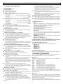
9) PROGRAMMING
The control panel provided with a microprocessor is supplied with
function parameters preset by the manufacturer, suitable for standard
installations. The predened parameters can be altered by means of either
the incorporated display programmer or Universal palmtop programmer.
In the case where programming is carried out by means of Universal
palmtop programmer, carefully read the instructions relating to Universal
palmtop programmer, and proceed in the following way.
Connect the Universal palmtop programmer to the control unit through
the UNIFLAT and UNIDA accessories (See g. 18). The LINX control unit
does not supply the Universal palmtop programmer with power, and
therefore requires an appropriate supply unit.
Enter the “CONTROL UNITS” menu, and the “PARAMETERS” submenu,
then scroll the display screenfuls using the up/down arrows to set the
numerical values of the parameters listed below.
For the function logics, refer to the “LOGIC” submenu.
In the case where programming is carried out by means of the incor-
porated programmer, refer to Fig. A and B and to the paragraph on
“Conguration”.
10) CONFIGURATION
The display programmer is used to set all the LINX control panel functions.
The programmer is provided with three pushbuttons for menu scrolling
and function parameter conguration:
+ menu scrolling/value increment key
- menu scrolling/value reduction key
OK Enter (conrm) key
The simultaneous pressure of the + and - keys is used to exit the active
menu and move to the preceding menu.
The modications made are only set if the OK key is subsequently pressed.
When the OK key is pressed for the rst time, the programming mode
is entered.
The following pieces of information appear on the display at rst:
- Control unit software version
- Number of total manoeuvres carried out (the value is expressed in
thousands, therefore the display constantly shows 0000 during the
rst thousand manoeuvres).
- Number of manoeuvres carried out since the latest maintenance opera-
tion (the value is expressed in thousands, therefore the display constantly
shows 0000 during the rst thousand manoeuvres).
- Number of memorised radio control devices.
When the OK key is pressed during the initial presentation phase, the
rst menu can be accessed directly.
Here follows a list of the main menus and the respective submenus avai-
lable.The predened parameter is shown between square brackets [ 0 ].
The writing appearing on the display is indicated between round brackets.
Refer to Figures A and B for the conguration procedure.
10.1) PARAMETER MENU (PARAm)
- Automatic Closing Time (TCA) [ 10s ]
Set the numerical value of the automatic closing time from 3 to 90
seconds.
- Motor 1 torque (m1 t) [ 50% ]
Set the numerical value of the motor 1 torque between 1% and 99%.
- Motor 2 torque (m2 t) [ 50% ]
Set the numerical value of the motor 2 torque between 1% and 99%.
- Motor 1 slow-down torque (m1 t slow) [ 45% ]
Set the numerical value for slow-down torque of motor 1 between
1% and 99%.
- Motor 2 slow-down torque (m2 t slow) [ 45% ]
Set the numerical value for slow-down torque of motor 2 between
1% and 99%.
NOTES: In case of obstacle detection, the Ampere-stop function
stops the leaf movement, reverses the motion for 1 sec. and then
halts in the STOP status. The motor slow-down torque represents the
maximum torque supplied to the motor during the slow-down phase.
It must be set to a lower value with respect to the motor torque, in
order to allow the Ampere-stop function to be also activated during
the slow-down phase.
WARNING: Check that the impact force value measured at
the points established by the EN 12445 standard is lower than
that specied in the EN 12453 standard.
Incorrect sensitivity setting can cause injuries to persons or
animals, or damage to things.
- Opening delay time (open delay time) [ 1s ]
Set the opening delay time for motor 2 relative to motor 1, between
1 and 10 seconds.
- Closing delay time (cls delay time) [ 1s ]
Set the closing delay time for motor 1 relative to motor 2, between
1 and 30 seconds.
- Motor 1 Normal Speed Time (m1 fast time) [ 15s ]
Set the time to normal speed (not slowed down), ranging from 1 to
30 seconds.
- Motor 2 Normal Speed Time (m2 fast time) [ 15s ]
Set the time to normal speed (not slowed down), ranging from 1 to
30 seconds.
Note: The slow-down time, on closing and on opening, is obtained
by timing one manoeuvre, and setting a lower value within this pa-
rameter. If, for example, one manoeuvre lasts 25 seconds, set “normal
speed time” to 20s to obtain 5s of slow-down time, both on closing
and on opening.
- Slow-down speed (slov speed) [ 0 ]
Set the slow-down speed by choosing from the following values:
0 – slow-down disabled
1 – slow-down to 50% of normal speed
VIRGO - 19
D811415_09

INSTALLATION MANUAL
2 – slow-down to 33% of normal speed.
3 – slow-down to 25% of normal speed.
10.2) LOGIC MENU (logic.)
- TCA (TCA) [ OFF ]
ON Activates automatic closing
OFF Excludes automatic closing
- 3 Steps (3 step) [ OFF ]
ON Enables 3-step logic. A Start impulse has the following eects:
door closed:..........................................................................................opens
on opening:................................stops and enters TCA (if congured)
door open:..............................................................................................closes
on closing:.....................................................................stops and reopens
OFF Enables 4-step logic. A Start impulse has the following eects:
door closed:...........................................................................................opens
on opening:................................stops and enters TCA (if congured)
door open:..............................................................................................closes
on closing:...................................stops and does not enter TCA (stop)
after stopping: .....................................................................................opens
- Impulse lock (ibl open) [ OFF ]
ON The Start impulse has no eect during the opening phase.
OFF The Start impulse becomes eective during the opening or
closing phase.
- Rapid closing (fast cls) [ OFF ]
ON Closes the gate after photocell disengagement, before waiting for
the end of the TCA set.
OFF Command not entered.
- Photocells on opening photc. open [ OFF ]
ON
In case of obscuring, this excludes photocell operation on opening.
During the closing phase, it immediately reverses the motion.
OFF In case of obscuring, the photocells are active both on opening
and on closing. When a photocell is obscured on closing, it reverses
the motion only after the photocell is disengaged.
- Photocell test (test phot) [ OFF ]
ON Activates photocell check
OFF Deactivates photocell check
If this setting is not activated (OFF), it inhibits the photocell che-
cking function, allowing connection of devices not provided with
additional checking contact.
- Gate-open or 2nd radio channel warning light (SCA 2ch) [ OFF ]
ON The output between terminals 25 and 26 is congured as Gate-
open warning light, in this case the 2nd radio channel controls
pedestrian opening.
OFF The output between terminals 25 and 26 is congured as 2nd
radio channel.
- Motors in operation (1 mot ON) [ OFF ]
ON Only motor 2 is in operation (terminals 1 and 2).
With this conguration, the pedestrian input is disabled.
OFF Both motors are in operation.
- Lock hold (bloc persist) [ OFF ]
ON To be used when opening and closing mechanical backstops
are tted.
This function activates leaf pressure on the backstop, without this
being considered as an obstacle by the ampere-stop sensor.
Then the leaf continues its stroke for another 0,5s, after intercep-
ting
the limit switches. Therefore the limit switches are triggered
slightly
in advance, and the leaves will stop perfectly on the end
stop plate.
OFF To be used when no mechanical backstops are tted.
Movement is exclusively stopped by the limit switches being trig-
gered; in this case it is necessary to set the opening and closing
limit switch triggering point with precision.
- Prealarm (preal) [ OFF ]
ON The blinker comes on about 3s before the motors start.
OFF The blinker comes on at the same time as the motors start
- Fixed code (fixed code) [ OFF ]
ON The receiver is congured for operation in xed-code mode, see
paragraph on “Radio Transmitter Cloning”.
OFF The receiver is congured for operation in rolling-code mode, see
paragraph on “Radio Transmitter Cloning”.
- Radio transmitter programming (radio prog) [ ON ]
ON This enables transmitter storage via radio (REPLAY, CLON
I):
1 – First press the hidden key (P1) and then the normal key (T1, T2,
T3 or T4) of a transmitter already memorised in standard mode
by means of the radio menu.
2 – Within 10s press the hidden key (P1) and the normal key (T1,
T2, T3 or T4) of a transmitter to be memorised.
The receiver exits the programming mode after 10s, other new
transmitters can be entered before the end of this time.
This mode does not require access to the control panel.
OFF This disables transmitter storage via radio.
The transmitters can only be memorised using the appropriate
Radio menu.
Wireless memorizing disabled: wireless learning of any remote
control disabled (including CLONI and REPLAY).
- Motor logic reversal (change mot.) [ OFF ]
ON Mot.1: it is the rst to start on opening and the last to start on closing.
Mot.2: it is the last to start on opening and the rst to start on closing.
OFF Mot.1: it is the last to start on opening and the rst to start on closing.
Mot.2: it is the rst to start on opening and the last to start on closing.
10.3) RADIO MENU (RADIO)
- Add
Allows you to add one key of a radio control device to the receiver
memory; after storage it displays a message showing the receiver
number in the memory location (from 01 to 64).
Add Start button (add start)
associates the required key to Start command
Add 2ch button (add 2ch)
associates the required key to 2nd radio channel
- Read (read)
Checks one key of a receiver; if stored it displays a message showing
the receiver number in the memory location (from 01 to 64), and the
key number (T1, T2, T3 or T4).
- Eliminate list (erease 64)
WARNING! Completely removes all memorised radio control devices
from the receiver memory.
- Receiver code reading (RX code)
This displays the code entered in the receiver.
Consult paragraphs 12-13-14-15 for further information concerning
the advanced functions of the Clonix incorporated receiver.
10.4) LANGUAGE MENU (language)
Allows you to set the language on the display programmer.
- ITALIAN (ITA)
- FRENCH (FRA)
- GERMAN (DEU)
- ENGLISH (ENG)
- SPANISH (ESP)
10.5) DEFAULT MENU (default)
Restores the preset default values on the control unit. After restoring, a
new autoset operation must be carried out.
10.6) DIAGNOSTICS AND MONITORING
The display on the LINX panel shows some useful information, both
during normal operation and in the case of malfunctions.
Diagnostics:
In the case of malfunctions, the display shows a message indicating
which device needs to be checked:
PED = PED input activation
STRT = START input activation
STOP = STOP input activation
PHOT = PHOT input activation
FLT = FAULT input activation for checked photocells
SWO1 = activation of Motor 1 opening limit switch input
SWC1 = activation of Motor 1 closing limit switch input
SWO2 = activation of Motor 2 opening limit switch input
SWC2 = activation of Motor 2 closing limit switch input
In the case where an obstacle is found, the LINX panel stops the door
and activates a reverse manoeuvre; at the same time the display shows
the “AMP” message.
Monitoring:
During the opening and closing phases, the display shows four digits
separated by a dot, for example 35.40. The digits are constantly updated
during the manoeuvre, and represent the maximum torque reached by
motor 1 (35) and motor 2 (40).
These values allow the torque setting to be corrected.
If the maximum torque value reached during the manoeuvre gets sensibly
20 - VIRGO
D811415_09

ENGLISH
INSTALLATION MANUAL
close to the value set in the parameter menu, malfunctions may occur
in the future following wear or slight door deformation.
It is therefore advisable to check the maximum torque reached during
some of the manoeuvres carried out in the course of installation, and
if necessary set a value about 15-20 percent points higher in the para-
meter menu.
10.7) AUTOSET MENU (autoset)
Allows you to automatically set the Motor torque.
WARNING!! The autoset operation is only to be carried out after checking
the exact leaf (opening/closing) movement, and correct limit-switch
activation.
As soon as the OK pushbutton is pressed, the “.... ....” message is displa-
yed, and the control unit executes an opening manoeuvre followed by
a closing manoeuvre, during which the minimum torque value needed
for leaf movement is automatically set.
During this phase, it is important to avoid obscuring the photocells, as
well as using the START, STOP or PED commands and the display.
After this, if autosetting has been successfully completed, the control
unit displays the “OK” message and, after pressing any key, returns to
the Autoset menu.
If, on the other hand, the control unit displays the “KO” message, it means
that the autoset procedure has not been successfully completed; it is
thus necessary to check the wear condition of the gate and the regular
movement of the leaves before proceeding to a new autoset operation.
WARNING! During the autoset phase, the obstacle detection function is
not active, therefore the installer must control the automation movement
and prevent persons and things from approaching or standing within
the automation working range.
In the case where buer batteries are used, autosetting must be carried
out with the control panel supplied by mains power voltage.
WARNING: Check that the impact force value measured at the
points established by the EN 12445 standard is lower than that
specied in the EN 12453 standard.
Incorrect sensitivity setting can cause injuries to persons or
animals, or damage to things.
11) STATISTICS
Having connected the Universal palmtop programmer to the control
unit, enter the CONTROL UNIT / STATISTICS menu and scroll the screenful
showing the statistical parameters:
- Board microprocessor software version.
- Number of cycles carried out. If motors are replaced, count the
number of manoeuvres carried out up to that time.
- Number of cycles carried out from the latest maintenance operation.
It is automatically set to zero after each self-diagnosis or parameter
writing.
- Date of latest maintenance operation. To be updated manually from
the appropriate menu “Update maintenance date”.
- Installation description. 16 characters can be entered for installation
identication.
12) INTEGRATED RECEIVER TECHNICAL SPECIFICATION
Receiver output channels:
- output channel 1, if activated, controls a START command.
- output channel 2, if activated, controls the excitation of the 2nd radio
channel relay for 1s.
Transmitter versions which can be used:
all Rolling Code transmitters compatible with
.
All REPLAY transmitters compatible with:
.
ANTENNA INSTALLATION
Use an antenna tuned to 433MHz.
For Antenna-Receiver connection, use RG8 coaxial cable.
The presence of metallic masses next to the antenna can interfere with
radioreception.Incaseofinsucienttransmitterrange,movethean-
tenna to a more suitable position.
13) RECEIVER CONFIGURATION
The on-board receiver combines characteristics of utmost safety in
copying variable code (rolling code) coding with the convenience of
carrying out transmitter “cloning” operations thanks to an exclusive
system.
Cloning a transmitter means creating a transmitter which can be au-
tomatically included within the list of the transmitters memorised in
the receiver, either as an addition or as a replacement of a particular
transmitter.
Cloning by replacement is used to create a new transmitter which takes
the place of the one previously memorised in the receiver; in this way
a specic transmitter can be removed from the memory and will no
longer be usable.
Therefore it will be possible to remotely program a large number of additional
transmitters or, for example, replacement transmitters for those which have
been lost, without making changes directly to the receiver.
When coding safety is not a decisive factor, the on-board receiver allows
you to carry out xed-code additional cloning which, although abando-
ning the variable code, provides a high number of coding combinations,
therefore keeping it possible to “copy” any transmitter which has already
been programmed.
PROGRAMMING
Transmitter storage can be carried out in manual mode or by means of the
Universal palmtop programmer which allows the complete installation
database to be managed through the Eedbase software.
In this second case, receiver programming takes place through the con-
nection of Universal palmtop programmer to the LINX control panel,
using the UNIFLAT and UNIDA accessories as indicated in Fig. 18.
14) MANUAL PROGRAMMING
In the case of standard installations where advanced functions are not
required, you can proceed to manual storage of the transmitters, making
reference to g. B for basic programming.
- If you wish the transmitter to activate output 1 (START) by means of
key1, key2, key3 or key4, enter the transmitter in menu “Start key”, as
in g. B.
- If you wish the transmitter to activate output 2 (2nd radio channel
relay) by means of key1, key2, key3 or key4, enter the transmitter in
menu “2nd ch. key”, as in g. B.
Note: Hidden key P1 appears dierently depending on the transmitter
model.
For transmitters with hidden key, press hidden key P1 (g. B1). For
transmitters without hidden key, the key P1 function corresponds
to simultaneously pressing the 4 transmitter keys or, after opening
the battery compartment, bridging the two P1 points by means of
a screwdriver (g. B2).
IMPORTANT NOTE: ATTACH THE ADH ESIVE KEY LABEL TO THE FIRST
MEMORISED TRANSMITTER (MASTER).
In the case of manual programming, the rst transmitter assigns the
key code to the receiver; this code is necessary in order to carry out
subsequent cloning of the radio transmitters.
15) RADIO-TRANSMITTER CLONING
Rolling-code cloning / Fixed-code cloning
Make reference to the Universal palmtop programmer Instructions and
the CLONIX Programming Guide.
15.1) ADVANCED PROGRAMMING: COLLECTIVE RECEIVERS
Make reference to the Universal palmtop programmer Instructions and
the CLONIX Programming Guide.
16) LIMIT SWITCH ADJUSTMENT (Fig.12)
• Identifytheopeningandclosinglimitswitches(FC1andFC2)taking
into account that:
FC1 corresponds the CLOSING limit switch
FC2 corresponds the OPENING limit switch.
• Withthegatecompletelyclosedoropened,rotatethecorresponding
cam until the relevant limit microswitch is heard being tripped, then
lock the cam into position by means of the appropriate screws.
• Checkthatthelimitswitchesaretriggeredcorrectly,byinitiatinga
few complete motor-driven opening and closing cycles.
• Ifthe“lockhold”logicissettoONintheLINXpanel,theleafcontinues
its stroke for about 0,5 seconds, in order to ensure stability and perfect
leaf stopping against the end-of-stroke backstops.
17) EMERGENCY MANOEUVRE (Fig.19)
In the case where the power supply is o, or any faults are present, the
manual emergency manoeuvre can be carried out by operating the
VIRGO - 21
D811415_09

INSTALLATION MANUAL
external release lever (Fig.1 ref.”S”).
1) Insert the release key and turn it clockwise (Fig.19 ref.”1”).
2) Move lever “S” until the lock is released (Fig.19 ref.”2”).
3) Keep the lever in the release position by turning the key clockwise
(Fig.19 ref.”3”).
4) Push the leaf slowly to open or close the gate.
To reactivate motor-driven operation, turn the key clockwise to free the
lever from its released position, then return it to its initial position for
normal operation.
18) MANUAL WIRE RELEASE DEVICE (Fig.13)
The manual emergency release can be operated by a wire device:
- Take all the metal cable out of the sheath and insert it into the release
lever.
- Lock the sheath and suitably adjust its position by means of the
appropriate screw.
- The cover is provided with a section to be torn o for the sheath to
go through.
- For further information, refer to the specic instructions for the release
device.
19) VIRGO BAT KIT INSTALLATION
- Fix the SBS board on the back of the panel box by means of a screw,
as indicated in Fig.14.
- Fix the board protection box (Fig.14 - “C”) supplied with the kit.
-
Position the two batteries on the supports, as indicated in Fig.14 (“A”).
- Secure the batteries using the bracket and screws supplied.
- Proceed to wire the SBS board with reference to the diagram in Fig.14.
20) AUTOMATION CHECK
Before allowing the automation to be used normally, carry out the
following procedure very carefully:
• Checkthecorrect functioningofallsafetydevices(limitmi-
croswitches, photocells, sensitive edges etc.).
• Checkthatthethrust(anti-squash)forceoftheleafiswithinthelimits
set by current regulations.
• Checkthemanualopeningcommand.
• Checktheopeningandclosingoperationswiththecontroldevices
in use.
• Checkthestandardandcustomisedelectronicfunctioninglogic.
21) AUTOMATION OPERATION
Since the automation can be remote-controlled by means of a remote
control device or a start button, and so out of sight, the good working
order of all the safety devices should be checked regularly. In the event
of any anomalous functioning of the safety devices, consult a speciali-
sed technician immediately. Keep children at a safe distance from the
automation operation area.
22) CONTROL
The automation is used for the power-operated opening and closing of the
gate. The control can be of a number of types (manual, remote-controlled,
magnetic badge access control, etc.) depending on requirements and
the characteristics of the installation. See the specic instructions for
the various control systems. Users of the automation must be instructed
about its control and operation.
23) MAINTENANCE
Disconnect the power supply when carrying out any maintenance
operations.
• LubricatetheVIRGOs of the manoeuvring arm regularly.
• Cleanthelensesofthephotocellseverysooften.
• Haveaqualiedperson(installer)checkcorrectmotortorquesetting.
• Intheeventofanyanomalousfunctioningwhichcannotberesolved,
disconnect the power supply and contact a specialised technician
(installer). Whilst the automation is out of order, activate the manual
release to allow manual opening and closing.
22 - VIRGO
D811415_09

MANUALE D’USO
2) SICUREZZA
ATTENZIONE! L’attuatore VIRGO non è dotato di
regolazione meccanica di coppia. È obbligatorio
utilizzare un quadro di comando del medesimo
costruttore, conforme ai requisiti essenziali di sicu-
rezza delle direttive 2006/95/CEE, 2004/108/CEE,
2006/42/CEE e dotato di adeguata regolazione
elettrica della coppia.
3) MANOVRA DI EMERGENZA (Fig.1)
In caso di assenza di tensione di rete o anomalie di
funzionamento, la manovra manuale di emergenza
può essere eseguita agendo sulla leva di sblocco
esterna (Fig.1 rif.”S”).
1) Inserire la chiave di sblocco e ruotarla in senso orario
(Fig.1 rif.”1”).
2) Azionare la leva “S” no ad ottenere lo sblocco
(Fig.1 rif.”2”).
3) Mantenere la leva in posizione di sblocco con
una rotazione antioraria della chiave (Fig.1 rif.”3”).
4) Spingere lentamente l’anta per aprire o chiudere
il cancello.
Per riattivare il funzionamento motorizzato,ruotare
la chiave in senso orario in modo da liberare la leva
dalla posizione di sblocco e riportarla nella posizione
iniziale di normale funzionamento.
ATTENZIONE! Prima di attivare la manovra manuale
vericare che ciò non possa causare una situazione
pericolosa.
USER’S MANUAL
2) SAFETY
ATTENTION! The VIRGO model controller is not
equipped with mechanical torque adjustment. It
is compulsory to use a control panel of the same
manufacturer, in compliance with the basic safety
requirements of directives 2006/95/CEE, 2004/108/
CEE, 2006/42/CEE equipped with appropriate elec-
tric adjusment of the torque.
3) EMERGENCY MANOEUVRE (Fig. 1)
In the case where the power supply is o, or any faults
are present, the manual emergency manoeuvre
can be carried out by operating the external
release lever (Fig.1 ref.”S”).
1) Insert the release key and turn it clockwise (Fig.1
ref.”1”).
2) Move lever “S” until the lock is released (Fig.1
ref.”2”).
3) Keep the lever in the release position by turning
Fig. 1
S
the key clockwise (Fig.1 ref.”3”).
4) Push the leaf slowly to open or close the gate.
To reactivate motor-driven operation, turn the
key clockwise to free the lever from its released
position, then return it to its initial position for
normal operation.
WARNING! Before carrying out the manual ma-
noeuvre make sure that this operation will not cre-
ate dangerous situations.
MANUALE D’USO / USER GUIDE:EMERGENCY OPERATION-
MANUEL D’UTILISATION
/ BEDIENUNGSHANDBUCH
MANUAL DE USO / MANUAL DE USO
VIRGO - 55
D811415_09

AVVERTENZE PER L’UTILIZZATORE ( I )
ATTENZIONE! Importanti istruzioni di sicurezza.
Leggere e seguire attentamente le Avvertenze
e le Istruzioni che accompagnano il prodotto
poiché un uso improprio può causare danni a
persone, animali o cose. Conservare le istruzioni
per consultazioni future e trasmetterle ad even-
tuali subentranti nell’uso dell’impianto.
Questo prodotto dovrà essere destinato solo
all’uso per il quale è stato espressamente insta-
llato. Ogni altro uso è da considerarsi improprio
e quindi pericoloso. Il costruttore non può essere
considerato responsabile per eventuali danni
causati da usi impropri, erronei e irragionevoli.
SICUREZZA GENERALE
Nel ringraziarVi per la preferenza accordata a questo
prodotto, la Ditta è certa che da esso otterrete le
prestazioni necessarie al Vostro uso.
Questo prodotto risponde alle norme riconosciute
della tecnica e della disposizioni relative alla si-
curezza se correttamente installato da personale
qualicato ed esperto (installatore professionale).
L’automazione, se installata ed utilizzata corretta-
mente, soddisfa gli standard di sicurezza nell’uso.
Tuttavia è opportuno osservare alcune regole di
comportamento per evitare inconvenienti acci-
dentali:
- Tenere bambini, persone e cose fuori dal raggio
d’azione dell’automazione, in particolare durante
il movimento.
- Non permettere a bambini di giocare o sostare nel
raggio di azione dell’automazione.
- Questa automazione non è destinata all’uso da
parte di bambini o da parte di persone con ridotte
capacità mentali, siche e sensoriali, o persone che
mancano di conoscenze adeguate a meno che
esse non abbiano potuto beneciare, attraverso
l’intermediazione di una persona responsabile della
loro sicurezza, di una sorveglianza o di istruzioni
riguardanti l’uso dell’apparecchio.
- I bambini devono essere sorvegliati per sincerarsi
che non giochino con l’apparecchio. Non permet-
tere ai bambini di giocare con i controlli ssi. Tenere
i telecomandi lontani dai bambini.
-
Evitare di operare in prossimità delle cerniere o organi
meccanici in movimento.
-
Non contrastare il movimento dell’anta e non ten-
tare di aprire manualmente la porta se non è stato
sbloccato l’attuatore con l’apposita manopola di
sblocco.
-
Non entrare nel raggio di azione della porta o can-
cello motorizzati durante il loro movimento.
- Non lasciare radiocomandi o altri dispositivi di
comando alla portata dei bambini onde evitare
azionamenti involontari.
- L’attivazione dello sblocco manuale potrebbe
causare movimenti incontrollati della porta se in
presenza di guasti meccanici o di condizioni di
squilibrio.
- In caso di apritapparelle: sorvegliare la tapparella
in movimento e tenere lontano le persone nché
non è completamente chiusa. Porre cura quando si
aziona lo sblocco se presente, poiché una tapparella
aperta potrebbe cadere rapidamente in presenza
di usura o rotture.
-
La rottura o l’usura di organi meccanici della porta
(parte guidata), quali ad esempio cavi, molle, sup-
porti, cardini, guide.. potrebbe generare pericoli. Far
controllare periodicamente l’impianto da personale
qualicato ed esperto (installatore professionale)
secondo quanto indicato dall’installatore o dal
costruttore della porta.
- Per ogni operazione di pulizia esterna, togliere
l’alimentazione di rete.
- Tenere pulite le ottiche delle fotocellule ed i dispo-
sitivi di segnalazione luminosa. Controllare che rami
ed arbusti non disturbino i dispositivi di sicurezza.
- Non utilizzare l’automatismo se necessita di
interventi di riparazione. In caso di guasto o di
malfunzionamento dell’automazione, togliere
l’alimentazione di rete sull’automazione, astenersi
da qualsiasi tentativo di riparazione o intervento
diretto e rivolgersi solo a personale qualicato ed
esperto (installatore professionale) per la neces-
saria riparazione o manutenzione. Per consentire
l’accesso, attivare lo sblocco di emergenza (se
presente).
-
Per qualsiasi intervento diretto sull’automazione o
sull’impianto non previsto dal presente manuale,
avvalersi di personale qualicato ed esperto (insta-
llatore professionale).
- Con frequenza almeno annuale far verifi-
care l’integrità e il corretto funzionamento
dell’automazione da personale qualificato ed
esperto (installatore professionale), in particolare
di tutti i dispositivi di sicurezza.
- Gli interventi d’installazione, manutenzione e
riparazione devono essere documentati e la
relativa documentazione tenuta a disposizione
dell’utilizzatore.
- Il mancato rispetto di quanto sopra può creare
situazioni di pericolo.
DEMOLIZIONE
L’eliminazione dei materiali va fatta rispettan-
do le norme vigenti. Non gettate il vostro
apparecchio scartato, le pile o le batterie usate
nei riuti domestici. Avete la responsabilità di
restituire tutti i vostri riuti da apparecchia-
ture elettriche o elettroniche lasciandoli in
un punto di raccolta dedicato al loro riciclo.
Tutto quello che non è espressamente previs-
to nel manuale d’uso, non è permesso. ll buon
funzionamento dell’operatore è garantito solo
se vengono rispettate le prescrizioni riportate
in questo manuale. La Ditta non risponde dei
danni causati dall’inosservanza delle indicazioni
riportate in questo manuale.
Lasciando inalterate le caratteristiche essenziali
del prodotto, la Ditta si riserva di apportare in
qualunque momento le modiche che essa ritie-
ne convenienti per migliorare tecnicamente, cos-
truttivamente e commercialmente il prodotto,
senza impegnarsi ad aggiornare la presente
pubblicazione.
USER WARNINGS (GB)
WARNING! Important safety instructions. Ca-
refully read and comply with the Warnings and
Instructions that come with the product as impro-
per use can cause injury to people and animals
and damage to property. Keep the instructions
for future reference and hand them on to any
new users.
This product is meant to be used only for the
purpose for which it was explicitly installed.
Any other use constitutes improper use and,
consequently, is hazardous. The manufacturer
cannot be held liable for any damage as a result
AVVERTENZE PER L’UTILIZZATORE D811767_05
VIRGO - 57
D811415_09

of improper, incorrect or unreasonable use.
GENERAL SAFETY
Thank you for choosing this product. The Firm is
condent that its performance will meet your ope-
rating needs.
This product meets recognized technical standards
and complies with safety provisions when installed
correctly by qualied, expert personnel (professional
installer).
If installed and used correctly, the automated system
will meet operating safety standards. Nonetheless,
it is advisable to observe certain rules of behaviour
so that accidental problems can be avoided:
- Keep adults, children and property out of range of
the automated system, especially while it is moving.
- Do not allow children to play or stand within range
of the automated system.
- This automated system is not meant for use by
children or by people with impaired mental, phy-
sical or sensory capacities, or people who do not
have suitable knowledge, unless a person who is
responsible for their safety provides them with
necessary supervision or instructions on how to
use the device.
- Children must be supervised to ensure they do not
play with the device. Do not allow children to play
with the xed controls. Keep remote controls out
of reach of children.
-
Do not work near hinges or moving mechanical parts.
- Do not hinder the leaf’s movement and do not
attempt to open the door manually unless the ac-
tuator has been released with the relevant release
knob.
- Keep out of range of the motorized door or gate
while they are moving.
- Keep remote controls or other control devices out
of reach of children in order to avoid the automated
system being operated inadvertently.
- The manual release’s activation could result in un-
controlled door movements if there are mechanical
faults or loss of balance.
- When using roller shutter openers: keep an eye
on the roller shutter while it is moving and keep
people away until it has closed completely. Exercise
care when activating the release, if such a device
is tted, as an open shutter could drop quickly in
the event of wear or breakage.
- The breakage or wear of any mechanical parts of
the door (operated part), such as cables, springs,
supports, hinges, guides…, may generate a hazard.
Have the system checked by qualied, expert per-
sonnel (professional installer) at regular intervals
according to the instructions issued by the installer
or manufacturer of the door.
- When cleaning the outside, always cut o mains
power.
- Keep the photocells’ optics and illuminating in-
dicator devices clean. Check that no branches or
shrubs interfere with the safety devices.
- Do not use the automated system if it is in need of
repair. In the event the automated system breaks
down or malfunctions, cut o mains power to the
system; do not attempt to repair or perform any
other work to rectify the fault yourself and instead
call in qualied, expert personnel (professional
installer) to perform the necessary repairs or main-
tenance. To allow access, activate the emergency
release (where tted).
- If any part of the automated system requires direct
work of any kind that is not contemplated herein,
employ the services of qualied, expert personnel
(professional installer).
- At least once a year, have the automated system, and
especially all safety devices, checked by qualied,
expert personnel (professional installer) to make
sure that it is undamaged and working properly.
- A record must be made of any installation, main-
tenance and repair work and the relevant docu-
mentation kept and made available to the user on
request.
- Failure to comply with the above may result in
hazardous situations.
SCRAPPING
Materials must be disposed of in accordance
with the regulations in force. Do not throw
away your discarded equipment or used bat-
teries with household waste. You are respon-
sible for taking all your waste electrical and
electronic equipment to a suitable recycling
centre.
Anything that is not explicitly provided for in the
user guide is not allowed. The operator’s proper
operation can only be guaranteed if the instruc-
tions given herein are complied with. The Firm
shall not be answerable for damage caused by
failure to comply with the instructions featured
herein.
While we will not alter the product’s essential
features, the Firm reserves the right, at any time,
to make those changes deemed opportune to
improve the product from a technical, design or
commercial point of view, and will not be required
to update this publication accordingly.
AVVERTENZE PER L’UTILIZZATORE D811767_05
58 - VIRGO
D811415_09

Bft Spa
Via Lago di Vico, 44
36015 Schio (VI)
T +39 0445 69 65 11
F +39 0445 69 65 22
www.bft.it
SPAIN
BFT GROUP ITALIBERICA DE
AUTOMATISMOS S.L.
08401 Granollers - (Barcelona)
www.bftautomatismos.com
FRANCE
AUTOMATISMES BFT FRANCE
69800 Saint Priest
www.bft-france.com
GERMANY
BFT TORANTRIEBSSYSTEME Gmb H
90522 Oberasbach
www.bft-torantriebe.de
UNITED KINGDOM
BFT AUTOMATION UK LTD
Stockport, Cheshire, SK7 5DA
www.bft.co.uk
IRELAND
BFT AUTOMATION LTD
Dublin 12
BENELUX
BFT BENELUX SA
1400 Nivelles
www.bftbenelux.be
POLAND
BFT POLSKA SP. Z O.O.
05-091 ZąBKI
www.bft.pl
CROATIA
BFT ADRIA D.O.O.
51218 Drazice (Rijeka)
www.bft.hr
PORTUGAL
BFT SA-COMERCIO DE
AUTOMATISMOS E MATERIAL DE
SEGURANCIA
3020-305 Coimbra
www.bftportugal.com
CZECH REPUBLIC
BFT CZ S.R.O.
Praha
www.bft.it
TURKEY
BFT OTOMATIK KAPI SISTEMELERI
SANAY VE
Istanbul
www.bftotomasyon.com.tr
RUSSIA
BFT RUSSIA
111020 Moscow
www.bftrus.ru
AUSTRALIA
BFT AUTOMATION AUSTRALIA
PTY LTD
Wetherill Park (Sydney)
www.bftaustralia.com.au
U.S.A.
BFT USA
Boca Raton
www.bft-usa.com
CHINA
BFT CHINA
Shanghai 200072
www.bft-china.cn
UAE
BFT Middle East FZCO
Dubai
-
 1
1
-
 2
2
-
 3
3
-
 4
4
-
 5
5
-
 6
6
-
 7
7
-
 8
8
-
 9
9
-
 10
10
-
 11
11
-
 12
12
-
 13
13
-
 14
14
-
 15
15
-
 16
16
-
 17
17
-
 18
18


in altre lingue
- English: BFT Virgo Installation guide
Documenti correlati
-
BFT Deimos BT A Manuale utente
-
-
BFT Virgo Smart BT A Manuale utente
-
-
-
-
-
-
-
Altri documenti
-
Nice ROAD 400 Instructions And Warnings For Installation And Use
-
 Moovo TS4 Manuale del proprietario
-
Nice Automation Road 200 Manuale del proprietario
-
-
 Allmatic XTILUS Manuale utente
-
 DTS ECO 500 Guida d'installazione
-


